


 Loading...
Compact I/O Thermocouple/mV Input
Module
Catalog Numbers 1769-IT6
User Manual
Important User Information
Solid state equipment has operational characteristics differing from those of electromechanical equipment. Safety Guidelines for the Application, Installation and Maintenance of Solid State Controls (publication SGI-1.1 available from your local Rockwell Automation sales office or online at http://www.rockwellautomation.com/literature/) describes some important differences between solid state equipment and hard-wired electromechanical devices. Because of this difference, and also because of the wide variety of uses for solid state equipment, all persons responsible for applying this equipment must satisfy themselves that each intended application of this equipment is acceptable.
In no event will Rockwell Automation, Inc. be responsible or liable for indirect or consequential damages resulting from the use or application of this equipment.
The examples and diagrams in this manual are included solely for illustrative purposes. Because of the many variables and requirements associated with any particular installation, Rockwell Automation, Inc. cannot assume responsibility or liability for actual use based on the examples and diagrams.
No patent liability is assumed by Rockwell Automation, Inc. with respect to use of information, circuits, equipment, or software described in this manual.
Reproduction of the contents of this manual, in whole or in part, without written permission of Rockwell Automation, Inc., is prohibited.
Throughout this manual, when necessary, we use notes to make you aware of safety considerations.
WARNING: Identifies information about practices or circumstances that can cause an explosion in a hazardous environment, which may lead to personal injury or death, property damage, or economic loss.
ATTENTION: Identifies information about practices or circumstances that can lead to personal injury or death, property damage, or economic loss. Attentions help you identify a hazard, avoid a hazard, and recognize the consequence
SHOCK HAZARD: Labels may be on or inside the equipment, for example, a drive or motor, to alert people that dangerous voltage may be present.
BURN HAZARD: Labels may be on or inside the equipment, for example, a drive or motor, to alert people that surfaces may reach dangerous temperatures.
IMPORTANT Identifies information that is critical for successful application and understanding of the product.
Allen-Bradley, Rockwell Software, Rockwell Automation, Compact I/O, MicroLogix, CompactLogix, RSLogix 500, RSLogix 5000, RSNetWorx, and TechConnect are trademarks of Rockwell Automation, Inc.
Trademarks not belonging to Rockwell Automation are property of their respective companies.

Summary of Changes
We have added an Important statement about the placement of the 1769-IT6 module with regard to the Compact I/O power supplies on page 18.
To help you find new and updated information in this release of the manual, we have included change bars as shown to the right of this paragraph.
Rockwell Automation Publication 1769-UM004B-EN-P - March 2010 |
3 |

Summary of Changes
Notes:
4 |
Rockwell Automation Publication 1769-UM004B-EN-P - March 2010 |

|
|
Table of Contents |
|
Preface |
|
|
Who Should Use This Manual . . . . . . . . . . . . . . . . . . |
. . . . . . . . . . . . . . . . . . . 9 |
|
Additional Resources . . . . . . . . . . . . . . . . . . . . . . . . . . . |
. . . . . . . . . . . . . . . . . . . 9 |
|
Conventions Used in This Manual . . . . . . . . . . . . . . |
. . . . . . . . . . . . . . . . . . . 9 |
|
Chapter 1 |
|
Overview |
General Description . . . . . . . . . . . . . . . . . . . . . . . . . . . . |
. . . . . . . . . . . . . . . . . . 11 |
|
Thermocouple/mV Inputs and Ranges . . . . . . . |
. . . . . . . . . . . . . . . . . . 11 |
|
Data Formats. . . . . . . . . . . . . . . . . . . . . . . . . . . . . . . |
. . . . . . . . . . . . . . . . . . 12 |
|
Filter Frequencies. . . . . . . . . . . . . . . . . . . . . . . . . . . |
. . . . . . . . . . . . . . . . . . 12 |
|
Hardware Features. . . . . . . . . . . . . . . . . . . . . . . . . . |
. . . . . . . . . . . . . . . . . . 12 |
|
General Diagnostic Features . . . . . . . . . . . . . . . . . |
. . . . . . . . . . . . . . . . . . 14 |
|
System Overview . . . . . . . . . . . . . . . . . . . . . . . . . . . . . . . |
. . . . . . . . . . . . . . . . . . 14 |
|
System Operation . . . . . . . . . . . . . . . . . . . . . . . . . . |
. . . . . . . . . . . . . . . . . . 14 |
|
Module Operation. . . . . . . . . . . . . . . . . . . . . . . . . . |
. . . . . . . . . . . . . . . . . . 15 |
|
Module Field Calibration . . . . . . . . . . . . . . . . . . . |
. . . . . . . . . . . . . . . . . . 16 |
Quick Start for Experienced Users
Installation and Wiring
Chapter 2
Before You Begin. . . . . . . . . . . . . . . . . . . . . . . . . . . . . . . . . . . . . . . . . . . . . . . . . 17
Required Tools and Equipment . . . . . . . . . . . . . . . . . . . . . . . . . . . . . . . . . . . 17
What You Need to Do. . . . . . . . . . . . . . . . . . . . . . . . . . . . . . . . . . . . . . . . . . . . 17
Chapter 3
Compliance to European Union Directives. . . . . . . . . . . . . . . . . . . . . . . . . 23 EMC Directive . . . . . . . . . . . . . . . . . . . . . . . . . . . . . . . . . . . . . . . . . . . . . . . 23 Low Voltage Directive . . . . . . . . . . . . . . . . . . . . . . . . . . . . . . . . . . . . . . . . 23 Power Requirements. . . . . . . . . . . . . . . . . . . . . . . . . . . . . . . . . . . . . . . . . . . . . . 24 General Considerations . . . . . . . . . . . . . . . . . . . . . . . . . . . . . . . . . . . . . . . . . . . 24 Hazardous Location Considerations . . . . . . . . . . . . . . . . . . . . . . . . . . . 24 Preventing Electrostatic Discharge . . . . . . . . . . . . . . . . . . . . . . . . . . . . . 25 Removing Power . . . . . . . . . . . . . . . . . . . . . . . . . . . . . . . . . . . . . . . . . . . . . 25 Selecting a Location. . . . . . . . . . . . . . . . . . . . . . . . . . . . . . . . . . . . . . . . . . . 25 System Assembly . . . . . . . . . . . . . . . . . . . . . . . . . . . . . . . . . . . . . . . . . . . . . . . . . 27
Mounting. . . . . . . . . . . . . . . . . . . . . . . . . . . . . . . . . . . . . . . . . . . . . . . . . . . . . . . . 28
Minimum Spacing . . . . . . . . . . . . . . . . . . . . . . . . . . . . . . . . . . . . . . . . . . . . 28 Panel Mounting . . . . . . . . . . . . . . . . . . . . . . . . . . . . . . . . . . . . . . . . . . . . . . 28
DIN Rail Mounting . . . . . . . . . . . . . . . . . . . . . . . . . . . . . . . . . . . . . . . . . . 29
Replace a Single Module within a System . . . . . . . . . . . . . . . . . . . . . . . . . . . 30
Rockwell Automation Publication 1769-UM004B-EN-P - March 2010 |
5 |

Table of Contents
Module Data, Status, and
Channel Configuration
Diagnostics and
Troubleshooting
Field Wiring Connections . . . . . . . . . . . . . . . . . . . . . . . . . . . . . . . . . . . . . . . . 30
System Wiring Guidelines . . . . . . . . . . . . . . . . . . . . . . . . . . . . . . . . . . . . . 30
Terminal Door Label . . . . . . . . . . . . . . . . . . . . . . . . . . . . . . . . . . . . . . . . . 32
Removing and Replacing the Terminal Block . . . . . . . . . . . . . . . . . . . 32
Wire the Finger-safe Terminal Block . . . . . . . . . . . . . . . . . . . . . . . . . . . 33
Wire the Module . . . . . . . . . . . . . . . . . . . . . . . . . . . . . . . . . . . . . . . . . . . . . 34
Cold Junction Compensation . . . . . . . . . . . . . . . . . . . . . . . . . . . . . . . . . . . . . 36
Calibration . . . . . . . . . . . . . . . . . . . . . . . . . . . . . . . . . . . . . . . . . . . . . . . . . . . . . . 36
Chapter 4
Module Memory Map . . . . . . . . . . . . . . . . . . . . . . . . . . . . . . . . . . . . . . . . . . . . 37 Accessing Input Image File Data . . . . . . . . . . . . . . . . . . . . . . . . . . . . . . . . . . . 38
Input Data File. . . . . . . . . . . . . . . . . . . . . . . . . . . . . . . . . . . . . . . . . . . . . . . . . . . 38
Input Data Values . . . . . . . . . . . . . . . . . . . . . . . . . . . . . . . . . . . . . . . . . . . . 38
General Status Bits (S0 through S7) . . . . . . . . . . . . . . . . . . . . . . . . . . . . 39
Open-circuit Flag Bits (OC0 through OC7) . . . . . . . . . . . . . . . . . . . . 39
Over-range Flag Bits (O0 through O7) . . . . . . . . . . . . . . . . . . . . . . . . . 40 Under-range Flag Bits (U0 through U7) . . . . . . . . . . . . . . . . . . . . . . . . 40
Configuring Channels . . . . . . . . . . . . . . . . . . . . . . . . . . . . . . . . . . . . . . . . . . . . 40
Configuration Data File. . . . . . . . . . . . . . . . . . . . . . . . . . . . . . . . . . . . . . . 41 Channel Configuration . . . . . . . . . . . . . . . . . . . . . . . . . . . . . . . . . . . . . . . 42
Enabling or Disabling a Channel (bit 15) . . . . . . . . . . . . . . . . . . . . . . . 43
Selecting Data Formats (bits 14…12) . . . . . . . . . . . . . . . . . . . . . . . . . . . 43 Selecting Input Type (bits 11…8) . . . . . . . . . . . . . . . . . . . . . . . . . . . . . . 45
Selecting Temperature Units (bit 7) . . . . . . . . . . . . . . . . . . . . . . . . . . . . 45
Determining Open-circuit Response (bits 6 and 5) . . . . . . . . . . . . . . 46 Selecting Input Filter Frequency (bits 2…0) . . . . . . . . . . . . . . . . . . . . . 46
Selecting Enable/Disable Cyclic Calibration (word 6, bit 0) . . . . . . 50
Determining Effective Resolution and Range . . . . . . . . . . . . . . . . . . . . . . . 50 Determining Module Update Time . . . . . . . . . . . . . . . . . . . . . . . . . . . . . . . . 69
Effects of Autocalibration on Module Update Time . . . . . . . . . . . . . 70
Calculating Module Update Time . . . . . . . . . . . . . . . . . . . . . . . . . . . . . 71 Impact of Autocalibration on Module Startup
During Mode Change. . . . . . . . . . . . . . . . . . . . . . . . . . . . . . . . . . . . . . . . . 73
Chapter 5
Safety Considerations. . . . . . . . . . . . . . . . . . . . . . . . . . . . . . . . . . . . . . . . . . . . . 75 Indicator Lights . . . . . . . . . . . . . . . . . . . . . . . . . . . . . . . . . . . . . . . . . . . . . . 75
Stand Clear of Equipment . . . . . . . . . . . . . . . . . . . . . . . . . . . . . . . . . . . . . 75
Program Alteration . . . . . . . . . . . . . . . . . . . . . . . . . . . . . . . . . . . . . . . . . . . 76 Safety Circuits. . . . . . . . . . . . . . . . . . . . . . . . . . . . . . . . . . . . . . . . . . . . . . . . 76
Module Operation versus Channel Operation . . . . . . . . . . . . . . . . . . . . . . 76 Power-up Diagnostics. . . . . . . . . . . . . . . . . . . . . . . . . . . . . . . . . . . . . . . . . . . . . 76
6 |
Rockwell Automation Publication 1769-UM004B-EN-P - March 2010 |

Table of Contents
|
Channel Diagnostics. . . . . . . . . . . . . . . . . . . . . . . . . . . . . . . . . . . . . . . . . . . . . |
. 77 |
|
Invalid Channel Configuration Detection . . . . . . . . . . . . . . . . . . . . . . |
77 |
|
Over-range or Under-range Detection. . . . . . . . . . . . . . . . . . . . . . . . . . |
77 |
|
Open-circuit Detection . . . . . . . . . . . . . . . . . . . . . . . . . . . . . . . . . . . . . . . |
77 |
|
Non-critical versus Critical Module Errors . . . . . . . . . . . . . . . . . . . . . . . . . |
78 |
|
Module Error Definition. . . . . . . . . . . . . . . . . . . . . . . . . . . . . . . . . . . . . . . . . . |
78 |
|
Module Error Field . . . . . . . . . . . . . . . . . . . . . . . . . . . . . . . . . . . . . . . . . . . |
78 |
|
Extended-error Information Field. . . . . . . . . . . . . . . . . . . . . . . . . . . . . . |
79 |
|
Error Codes. . . . . . . . . . . . . . . . . . . . . . . . . . . . . . . . . . . . . . . . . . . . . . . . . . . . . . |
80 |
|
Module Inhibit Function . . . . . . . . . . . . . . . . . . . . . . . . . . . . . . . . . . . . . . . . . |
82 |
|
Contacting Rockwell Automation . . . . . . . . . . . . . . . . . . . . . . . . . . . . . . . . . |
82 |
|
Appendix A |
|
Specifications |
Accuracy versus Thermocouple Temperature and Filter Frequency . . . |
87 |
|
Temperature Drift . . . . . . . . . . . . . . . . . . . . . . . . . . . . . . . . . . . . . . . . . . . . . . |
105 |
|
Appendix B |
|
Two’s Complement Binary |
Positive Decimal Values. . . . . . . . . . . . . . . . . . . . . . . . . . . . . . . . . . . . . . . . . . |
111 |
Numbers |
Negative Decimal Values. . . . . . . . . . . . . . . . . . . . . . . . . . . . . . . . . . . . . . . . . |
112 |
|
Appendix C |
|
Thermocouple Descriptions |
International Temperature Scale of 1990 . . . . . . . . . . . . . . . . . . . . . . . . . . |
113 |
|
Type B Thermocouples . . . . . . . . . . . . . . . . . . . . . . . . . . . . . . . . . . . . . . . . . . |
113 |
|
Type E Thermocouples . . . . . . . . . . . . . . . . . . . . . . . . . . . . . . . . . . . . . . . . . . |
115 |
|
Type J Thermocouples. . . . . . . . . . . . . . . . . . . . . . . . . . . . . . . . . . . . . . . . . . . |
117 |
|
Type K Thermocouples . . . . . . . . . . . . . . . . . . . . . . . . . . . . . . . . . . . . . . . . . . |
119 |
|
Type N Thermocouples. . . . . . . . . . . . . . . . . . . . . . . . . . . . . . . . . . . . . . . . . . |
121 |
|
Type R Thermocouples . . . . . . . . . . . . . . . . . . . . . . . . . . . . . . . . . . . . . . . . . . |
123 |
|
Type S Thermocouples . . . . . . . . . . . . . . . . . . . . . . . . . . . . . . . . . . . . . . . . . . |
124 |
|
Type T Thermocouples . . . . . . . . . . . . . . . . . . . . . . . . . . . . . . . . . . . . . . . . . . |
126 |
|
References . . . . . . . . . . . . . . . . . . . . . . . . . . . . . . . . . . . . . . . . . . . . . . . . . . . . . . |
129 |
|
Appendix D |
|
Using Thermocouple Junctions |
Using a Grounded Junction Thermocouple. . . . . . . . . . . . . . . . . . . . . . . . |
135 |
|
Using an Ungrounded (isolated) Junction Thermocouple . . . . . . . . . . |
137 |
|
Using an Exposed Junction Thermocouple . . . . . . . . . . . . . . . . . . . . . . . . |
137 |
Module Configuration by Using a MicroLogix 1500 System and RSLogix 500 Software
Appendix E
Module Addressing. . . . . . . . . . . . . . . . . . . . . . . . . . . . . . . . . . . . . . . . . . . . . . 139
1769-IT6 Configuration File . . . . . . . . . . . . . . . . . . . . . . . . . . . . . . . . . 140
Configuring the 1769-IT6 Module in a MicroLogix 1500 System . . . 141
Rockwell Automation Publication 1769-UM004B-EN-P - March 2010 |
7 |

Table of Contents
Configuring Your 1769-IT6 Module with the Generic Profile for CompactLogix Controllers in RSLogix 5000 Software
Configuring Your 1769-IT6 Module in a Remote DeviceNet System with a 1769-ADN DeviceNet Adapter
Glossary
Index
Appendix F
Configuring I/O Modules. . . . . . . . . . . . . . . . . . . . . . . . . . . . . . . . . . . . . . . . 148
Configuring a 1769-IT6 Thermocouple Module . . . . . . . . . . . . . . . . . . . 150
Appendix G
Configuring the 1769-IT6 Module . . . . . . . . . . . . . . . . . . . . . . . . . . . . . . . 154
8 |
Rockwell Automation Publication 1769-UM004B-EN-P - March 2010 |

Preface
Who Should Use
This Manual
Additional Resources
Conventions Used in
This Manual
Read this preface to familiarize yourself with the rest of the manual.
Use this manual if you are responsible for designing, installing, programming, or troubleshooting control systems that use Allen-Bradley Compact I/O and/or compatible controllers, such as MicroLogix 1500 or CompactLogix.
These documents contain additional information concerning related Rockwell Automation products.
Resource |
Description |
|
|
MicroLogix 1500 User Manual, |
A user manual containing information on how to |
publication 1764-UM001 |
install, use, and program your MicroLogix 1500 |
|
controller |
|
|
1769-ADN DeviceNet Adapter User Manual, |
An overview of the Compact I/O system |
publication 1769-UM001 |
|
|
|
CompactLogix User Manual, |
A user manual that contains information on |
publication 1769-UM007 |
installing, using, and programming |
|
CompactLogix controllers |
|
|
Programmable Controller Grounding and Wiring |
In-depth information on grounding and wiring |
Guidelines, publication 1770-4.1 |
Allen-Bradley programmable controllers |
|
|
You can view or download publications at http://www.rockwellautomation.com/literature. To order paper copies of technical documentation, contact your local Rockwell Automation distributor or sales representative.
These conventions are used throughout this manual:
•Bulleted lists (like this one) provide information not procedural steps.
•Numbered lists provide sequential steps or hierarchical information.
•Bold type is used for emphasis.
Rockwell Automation Publication 1769-UM004B-EN-P - March 2010 |
9 |

Preface
Notes:
10 |
Rockwell Automation Publication 1769-UM004B-EN-P - March 2010 |
Chapter 1
Overview
General Description
This chapter describes the 1769-IT6 Thermocouple/mV Input Module and explains how the module reads thermocouple or millivolt analog input data. Included is information about:
•the module’s hardware and diagnostic features.
•an overview of system and module operation.
•compatibility.
The thermocouple/mV input module supports thermocouple and millivolt signal measurement. It digitally converts and stores thermocouple and/or millivolt analog data from any combination of up to six thermocouple or millivolt analog sensors. Each input channel is individually configurable via software for a specific input device, data format and filter frequency, and provides open-circuit, over-range and under-range detection and indication.
Thermocouple/mV Inputs and Ranges
The table below defines thermocouple types and their associated full-scale temperature ranges. The second table lists the millivolt analog input signal ranges that each channel will support. To determine the practical temperature range your thermocouple supports, see the specifications in Appendix A.
Thermocouple |
°C Temperature Range |
°F Temperature Range |
Type |
|
|
|
|
|
J |
-210…1200 °C |
-346…2192 °F |
|
|
|
K |
-270…1370 °C |
-454…2498 °F |
|
|
|
T |
-270…400 °C |
-454…752 °F |
|
|
|
E |
-270…1000 °C |
-454…1832 °F |
|
|
|
R |
0…1768 °C |
32…3214 °F |
|
|
|
S |
0…1768 °C |
32…3214 °F |
|
|
|
B |
300…1820 °C |
572…3308 °F |
|
|
|
N |
-210…1300 °C |
-346…2372 °F |
|
|
|
C |
0…2315 °C |
32…4199 °F |
|
|
|
CJC Sensor |
0…85 °C |
32…185 °F |
|
|
|
Millivolt Input Type |
Range |
|
|
± 50 mV |
-50…50 mV |
|
|
± 100 mV |
-100…100 mV |
|
|
Rockwell Automation Publication 1769-UM004B-EN-P - March 2010 |
11 |

Chapter 1 |
Overview |
|
|
Data Formats
The data can be configured on board each module as:
•engineering units x 1.
•engineering units x 10.
•scaled-for-PID.
•percent of full-scale.
•raw/proportional data.
Filter Frequencies
The module uses a digital filter that provides high frequency noise rejection for the input signals. The filter is programmable, allowing you to select from these six different filter frequencies for each channel:
•10 Hz
•50 Hz
•60 Hz
•250 Hz
•500 Hz
•1000 Hz
Hardware Features
The module contains a removable terminal block. Channels are wired as differential inputs. Two cold junction compensation (CJC) sensors are attached to the terminal block to enable accurate readings from each channel. These sensors compensate for offset voltages introduced into the input signal as a result of the cold-junction where the thermocouple wires are connected to the module.
Module configuration is normally done via the controller’s programming software. In addition, some controllers support configuration via the user program. In either case, the module configuration is stored in the memory of the controller. Refer to your controller’s user manual for more information.
12 |
Rockwell Automation Publication 1769-UM004B-EN-P - March 2010 |
Overview |
Chapter 1 |
|
|
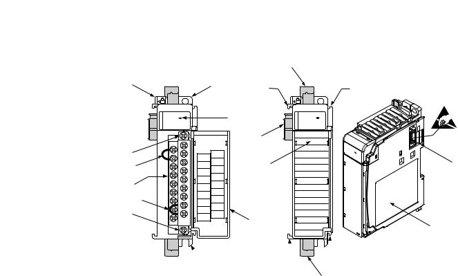
Figure 1 - Hardware Features
8a
1 |
2a |
|
|
OK |
3 |
|
Thermocouple/mV |
|
|
DANGER |
|
|
Do Not Remove RTB Under Power |
|
10a |
Unless Area is Non-Hazardous |
|
CJC 0+ |
|
|
|
NC |
|
11 |
IN 0+ |
|
IN 0- |
||
|
CJC 0- |
|
|
IN 3+ |
|
|
IN 1+ |
|
|
IN 3- |
|
10 |
IN 1- |
|
IN 2+ |
||
|
IN 4+ |
|
11 |
IN 4- |
|
IN 5+ |
2- |
|
|
IN |
|
10b |
CJC 1- |
|
IN 5- |
|
|
NC |
1+ |
|
|
CJC |
|
|
Ensure |
|
|
Adjacent Bus Lever is |
|
|
Unlatched/Latched Before/After |
|
|
Removing/Inserting Module |
|
|
1769-IT6 |
|
 2b
2b
7a |
7a |
|
OK |
|
Thermocouple/mV |
5a |
|
9 |
5b |
4
6
7b
 7b
7b
8b
Item |
Description |
|
|
1 |
Bus lever |
|
|
2a |
Upper-panel mounting tab |
|
|
2b |
Lower-panel mounting tab |
|
|
3 |
Module status indicator |
|
|
4 |
Module door with terminal identification label |
|
|
5a |
Movable bus connector (bus interface) with female pins |
|
|
5b |
Stationary bus connector (bus interface) with male pins |
|
|
6 |
Nameplate label |
|
|
7a |
Upper tongue-and-groove slots |
|
|
7b |
Lower tongue-and-groove slots |
|
|
8a |
Upper DIN-rail latch |
|
|
8b |
Lower DIN-rail latch |
|
|
9 |
Write-on label for user identification tags |
|
|
10 |
Removable terminal block (RTB) with finger-safe cover |
|
|
10a |
RTB upper-retaining screw |
|
|
10b |
RTB lower-retaining screw |
|
|
11 |
CJC sensors |
|
|
Rockwell Automation Publication 1769-UM004B-EN-P - March 2010 |
13 |

Chapter 1 |
Overview |
|
|
General Diagnostic Features
System Overview
The module contains a diagnostic status indicator that helps you identify the source of anomalies that may occur during powerup or during normal channel operation. The status indicator indicates both status and power. Power-up and channel diagnostics are explained in Chapter 5, Diagnostics and Troubleshooting.
The modules communicate to the controller through the bus interface. The modules also receive 5 and 24V DC power through the bus interface.
System Operation
At powerup, the module performs a check of its internal circuits, memory, and basic functions. During this time, the module status indicator remains off. If no faults are found during power-up diagnostics, the module status indicator is turned on.
After power-up checks are complete, the module waits for valid channel configuration data. If an invalid configuration is detected, the module generates a configuration error. Once a channel is properly configured and enabled, it continuously converts the thermocouple or millivolt input to a value within the range selected for that channel.
Each time a channel is read by the input module, that data value is tested by the module for an over-range, under-range, open-circuit, or ‘input data not valid’ condition. If such a condition is detected, a unique bit is set in the channel status word. The channel status word is described in Input Data File on page 38.
By using the module image table, the controller reads the two’s complement binary converted thermocouple or millivolt data from the module. This typically occurs at the end of the program scan or when commanded by the control program. If the controller and the module determine that the data transfer has been made without error, the data is used in the control program.
14 |
Rockwell Automation Publication 1769-UM004B-EN-P - March 2010 |
Overview |
Chapter 1 |
|
|
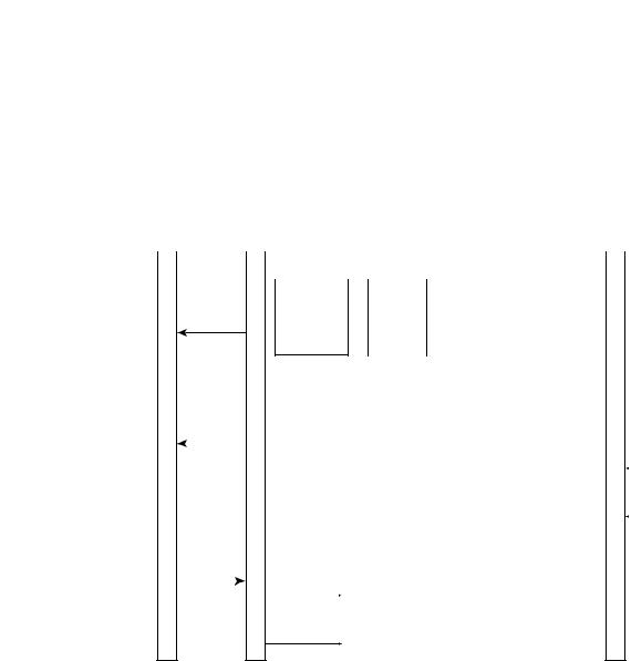
Module Operation
When the module receives a differential input from an analog device, the module’s circuitry multiplexes the input into an A/D converter. The converter reads the signal and converts it as required for the type of input. The module also continuously samples the CJC sensors and compensates for temperature changes at the terminal block cold junction, between the thermocouple wire and the input channel.
|
|
16-pin Backplane |
|
|
|
|
|
|
|
|
|||||
Controller Connector |
|
|
|
|
|
18-pin Terminal Block |
|||||||||
|
|
|
|
|
|
|
|
|
|
|
|
|
|
|
|
|
|
|
|
|
|
|
|
|
|
|
|
|
|
||
|
|
|
|
|
|
|
|
1769 Bus |
|
|
Opto-- |
||||
|
|
Module |
|
|
couplers |
||||||||||
|
|
ASIC |
|
|
|
||||||||||
|
|
|
|
|
|
|
|
|
|
|
|
|
|
|
|
|
|
Data |
|
(3) |
|
|
|
||||||||
|
|
|
|
|
|
|
|||||||||
|
|
|
|
|
|
|
|
|
|
|
|
|
|
|
|
|
|
|
|
|
|
|
|
|
Module |
|
|
|
Microprocessor |
|
|
|
|
|
|
|
|
|
|
||||||||
|
|
|
|
|
|
|
|
|
|
|
|
|
|
|
|
|
|
|
|
|
|||
|
Status |
|
|
|
|
|
|
|
|
|
|
|
|
|
|
|
|
|
|
|
6 Differential |
||
|
|
|
|
|
|
|
|
|
|
|
|
|
|
|
|
|
|
|
|
|
|
|
|
|
|
|
|
|
|
|
|
|
|
|
|
|
|
|
|
|
|
|
|
|
|
|
|
|
|
|
|
|
|
|
|
|
A/D |
|
|
Differential |
|
Input |
|
|
|
Thermocouple/mV |
|||||
|
|
|
|
|
|
|
|
|
|
|
|
|
|
||||||||||
|
|
|
|
|
|
|
|
|
|
|
8:1 |
|
Protection |
|
|
|
Inputs |
||||||
|
|
|
|
|
|
|
|
Converter |
|
|
|
|
|
|
|||||||||
|
|
|
|
|
|
|
|
|
|
Multiplexer |
|
Circuitry |
|
|
|
|
|||||||
|
|
|
|
|
|
|
|
|
|
|
|
|
|
|
|||||||||
|
|
|
|
|
|
|
|
|
|
|
|
|
|
|
|
|
|
|
|
||||
|
|
|
|
|
|
|
|
|
|
|
|
|
|
|
|
|
Circuits |
|
|
|
|
|
CJC Sensors |
|
Module |
|
|
|
|
|
|
|
|
|
|
|
|
|
|
|
|
|
|
|
|||
|
|
|
|
|
|
|
|
|
|
|
|
|
|
|
|
|
|
|
|
|
|||
|
|
|
|
|
|
|
|
|
|
|
|
|
|
|
|
|
|
|
|
|
|||
Configuration |
+5V |
|
+15V GND |
-15V |
|
|
|
|
|
|
|||||||||||||
|
Data |
+24V DC |
|
|
|
|
|
|
|
|
|
|
|
|
|
|
|
|
|
|
|||
|
|
|
|
|
|
|
|
|
|
|
|
|
|
|
|
|
|
|
|
|
|
||
|
|
|
|
|
|
|
|
Isolated Power |
|
|
|
|
|
|
|
|
|
|
|||||
|
|
|
|
24V GND |
|
|
|
Supply |
|
|
|
|
|
|
|
|
|
|
|||||
|
|
|
|
|
|
|
|
|
|
|
|
|
|
|
|
|
|
|
|
|
|
||
|
|
|
|
|
|
|
|
|
|
|
|
|
|
|
|
|
|
|
|
|
|
|
|
Each channel can receive input signals from a thermocouple or millivolt analog input device, depending upon how you configured the channel.
When configured for thermocouple input types, the module converts the analog input voltages into cold-junction compensated and linearized digital temperature readings. The module uses the National Institute of Standards and Technology (NIST) ITS-90 standard for linearization for all thermocouple types (J, K, T, E, R, S, B, N, C).
When configured for millivolt inputs, the module converts the analog values directly into digital counts.
Rockwell Automation Publication 1769-UM004B-EN-P - March 2010 |
15 |

Chapter 1 |
Overview |
|
|
Module Field Calibration
The module provides autocalibration, which compensates for offset and gain drift of the A/D converter caused by a temperature change within the module. An internal, high-precision, low drift voltage and system ground reference is used for this purpose. The input module performs autocalibration when a channel is initially enabled. In addition, you can program the module to perform a calibration cycle once every 5 minutes. See Selecting Enable/Disable Cyclic Calibration (word 6, bit 0) on page 50 for information on configuring the module to perform periodic autocalibration.
16 |
Rockwell Automation Publication 1769-UM004B-EN-P - March 2010 |

Chapter 2
Quick Start for Experienced Users
Before You Begin
Required Tools and
Equipment
What You Need to Do
This chapter can help you to get started using the 1769-IT6 thermocouple/mV input module. We base the procedures here on the assumption that you have an understanding of Allen-Bradley controllers. You should understand electronic process control and be able to interpret the ladder logic instructions required to generate the electronic signals that control your application.
Because it is a start-up guide for experienced users, this chapter does not contain detailed explanations about the procedures listed. It does, however, reference other chapters in this book where you can get more information about applying the procedures described in each step.
If you have any questions or are unfamiliar with the terms used or concepts presented in the procedural steps, always read the referenced chapters and other recommended documentation before trying to apply the information.
Have these tools and equipment ready:
•Medium blade or cross-head screwdriver
•Thermocouple or millivolt analog input device
•Shielded, twisted-pair cable for wiring
(Belden 8761 or equivalent for millivolt inputs, or shielded thermocouple extension wire for thermocouple inputs)
•Controller
(for example, a MicroLogix 1500 or CompactLogix controller)
•Programming device and software
(for example, RSLogix 500 or RSLogix 5000 software)
This chapter covers this information.
1.Be sure that your 1769 system power supply has sufficient current output to support your system configuration.
2.Attach and lock the module.
3.Wire the module.
4.Configure the module.
5.Go through the start-up procedure.
6.Monitor the module status to check if the module is operating correctly.
Rockwell Automation Publication 1769-UM004B-EN-P - March 2010 |
17 |
Chapter 2 Quick Start for Experienced Users
Step 1 |
Be sure that your 1769 system power supply(1) has sufficient current |
Reference |
|
output to support your system configuration. |
Chapter 3 |
|
|
(Installation and Wiring) |
|
|
|
(1)The system power supply could be catalog number 1769-PA2, 1769-PB2, 1769-PA4, 1769-PB4, or the internal supply of the MicroLogix 1500 packaged controller.
The module’s maximum current draw is:
•100 mA for 5V DC.
•40 mA for 24V DC.
Step 2 |
Attach and lock the module. |
Reference |
Chapter 3
(Installation and Wiring)
TIP |
The module can be panel or DIN rail mounted. Modules can be |
|
assembled before or after mounting. |
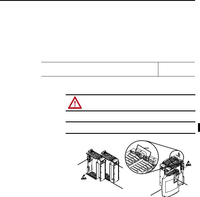
ATTENTION: Remove power before removing or inserting this module. If you remove or insert a module with power applied, an electrical arc may occur.
IMPORTANT To reduce the effects of electrical noise, install the 1769-IT6 module at least two slots away from Compact I/O 120/240V AC power supplies.
3
4
2
1
6
1
5
1.Check that the bus lever of the module to be installed is in the unlocked (fully right) position.
2.Use the upper and lower tongue-and-groove slots (1) to secure the modules together (or to a controller).
3.Move the module back along the tongue-and-groove slots until the bus connectors (2) line up with each other.
4.Push the bus lever back slightly to clear the positioning tab (3) by using your fingers or a small screwdriver.
5.Move the bus lever fully to the left (4) until it clicks to allow communication between the controller and module.
18 |
Rockwell Automation Publication 1769-UM004B-EN-P - March 2010 |
Quick Start for Experienced Users |
Chapter 2 |
|
|
Be sure the bus lever is locked firmly in place.
ATTENTION: When attaching I/O modules, it is very important that the bus connectors are securely locked together to be sure of proper electrical connection.
6.Attach an end cap terminator (5) to the last module in the system by using the tongue-and-groove slots as before.
7.Lock the end cap bus terminator (6).
IMPORTANT A 1769-ECR or 1769-ECL right or left end cap respectively must be used to terminate the end of the 1769 communication bus.
Step 3 |
Wire the module. |
Reference |
Chapter 3
(Installation and Wiring)
Follow these guidelines when wiring the module:
General Guidelines
•Power and input wiring must be in accordance with Class I, Division 2 wiring methods, Article 501-4(b) of the National Electric Code, NFPA 70, and in accordance with the authority having jurisdiction.
•Channels are isolated from one another by ±10V DC maximum.
•Route field wiring away from any other wiring and keep it as far as possible from sources of electrical noise, such as motors, transformers, contactors, and AC devices. As a general rule, allow at least 15.2 cm (6 in.) of separation for every 120V of power.
•Routing field wiring in a grounded conduit can reduce electrical noise.
•If field wiring must cross AC or power cables, be sure that they cross at right angles.
•If multiple power supplies are used with analog millivolt inputs, the power supply commons must be connected.
Terminal Block Guidelines
•Do not use the module’s NC terminals as connection points.
•Do not tamper with or remove the CJC sensors on the terminal block. Removal of either one or both sensors will reduce accuracy.
•For millivolt sensors, use Belden 8761 shielded, twisted-pair wire (or equivalent) to be sure of proper operation and high immunity to electrical noise.
•For a thermocouple, use the shielded, twisted-pair thermocouple extension lead wires specified by the thermocouple manufacturer. Using the incorrect type of thermocouple extension wire or not following the correct polarity will cause invalid readings.
Rockwell Automation Publication 1769-UM004B-EN-P - March 2010 |
19 |

Chapter 2 Quick Start for Experienced Users
•To be sure of optimum accuracy, limit overall cable impedance by keeping a cable as short as possible. Locate the module as close to input devices as the application permits.
Grounding Guidelines
ATTENTION: The possibility exists that a grounded or exposed thermocouple can become shorted to a potential greater than that of the thermocouple itself. Due to possible shock hazard, take care when wiring grounded or exposed thermocouples. See Appendix D, Using Thermocouple Junctions.
•This product is intended to be mounted to a well-grounded mounting surface such as a metal panel. Additional grounding connections from the module’s mounting tabs or DIN rail (if used) are not required unless the mounting surface cannot be grounded.
•Keep cable shield connections to ground as short as possible.
•Ground the shield drain wire at one end only. The preferred location is as follows.
–For grounded thermocouples or millivolt sensors, this is at the sensor end.
–For insulated/ungrounded thermocouples, this is at the module end. Contact your sensor manufacturer for additional details.
•Refer to Industrial Automation Wiring and Grounding Guidelines, Allen-Bradley publication 1770-4.1, for additional information.
Figure 2 - Terminal Connections with CJC Sensors
CJC 0+ |
NC |
|
|
IN 0+ |
|
CJC 0- |
IN 0- |
|
IN 3+ |
IN 1 + |
|
IN 3- |
IN 1- |
|
IN 4+ |
IN 2+ |
|
IN 4- |
||
|
||
IN 5+ |
IN 2- |
|
CJC 1- |
||
|
||
IN 5- |
|
|
NC |
CJC 1+ |
20 |
Rockwell Automation Publication 1769-UM004B-EN-P - March 2010 |
Quick Start for Experienced Users |
Chapter 2 |
|
|
Step 4 |
Configure the module. |
Reference |
Chapter 4
(Module Data, Status, and Channel
Configuration)
The configuration file is typically modified by using the programming software compatible with your controller. It can also be modified through the control program, if supported by the controller. See Channel Configuration on page 42 for more information.
Step 5 |
Go through the start-up procedure. |
Reference |
Chapter 5 (Diagnostics and Troubleshooting)
1.Apply power to the controller system.
2.Download your program, which contains the thermocouple module configuration settings, to the controller.
3.Put the controller in Run mode.
During a normal startup, the module status indicator turns on.
TIP |
If the module status indicator does not turn on, cycle power. If the |
|
condition persists, contact your local distributor or Rockwell |
|
Automation for assistance. |
Step 6 Monitor the module status to check if the module is operating correctly
Reference
Chapter 5 (Diagnostics and Troubleshooting)
Module and channel configuration errors are reported to the controller. These errors are typically reported in the controller’s I/O status file.
Channel status data is also reported in the module’s input data table, so these bits can be used in your control program to flag a channel error.
Rockwell Automation Publication 1769-UM004B-EN-P - March 2010 |
21 |

Chapter 2 Quick Start for Experienced Users
Notes:
22 |
Rockwell Automation Publication 1769-UM004B-EN-P - March 2010 |

Chapter 3
Installation and Wiring
Compliance to European Union Directives
This chapter tells you how to:
•determine the power requirements for the modules.
•avoid electrostatic damage.
•install the module.
•wire the module’s terminal block.
•wire input devices.
This product is approved for installation within the European Union and EEA regions. It has been designed and tested to meet the following directives.
EMC Directive
The 1769-IT6 module is tested to meet Council Directive 89/336/EEC Electromagnetic Compatibility (EMC) and the following standards, in whole or in part, documented in a technical construction file:
•EN 50081-2
EMC—Generic Emission Standard, Part 2 - Industrial Environment
•EN 50082-2
EMC—Generic Immunity Standard, Part 2 - Industrial Environment
This product is intended for use in an industrial environment.
Low Voltage Directive
This product is tested to meet Council Directive 73/23/EEC Low Voltage, by applying the safety requirements of EN 61131-2 Programmable Controllers, Part 2 – Equipment Requirements and Tests.
For specific information required by EN61131-2, see the appropriate sections in this publication, as well as the Industrial Automation, Wiring and Grounding Guidelines for Noise Immunity, publication 1770-4.1.
Rockwell Automation Publication 1769-UM004B-EN-P - March 2010 |
23 |

Chapter 3 Installation and Wiring
Power Requirements
The module receives power through the bus interface from the 5/24V DC system power supply. The maximum current drawn by the module is:
•100 mA at 5V DC.
•40 mA at 24V DC.
General Considerations
Compact I/O modules are suitable for use in an industrial environment when installed in accordance with these instructions. Specifically, this equipment is
intended for use in clean, dry environments (Pollution Degree 2(1)) and to circuits not exceeding Over Voltage Category II(2) (IEC 60664-1).(3)
Hazardous Location Considerations
This equipment is suitable for use in Class I, Division 2, Groups A, B, C, D or non-hazardous locations only. The following WARNING statement applies to use in hazardous locations.
WARNING: Explosion Hazard
• Substitution of components may impair suitability for Class I, Division 2.
• Do not replace components or disconnect equipment unless power has been switched off or the area is known to be non-hazardous.
•Do not connect or disconnect components unless power has been switched off or the area is known to be non-hazardous.
•This product must be installed in an enclosure.
•All wiring must comply with N.E.C. article 501-4(b).
(1)Pollution Degree 2 is an environment where, normally, only non-conductive pollution occurs except that occasionally a temporary conductivity caused by condensation shall be expected.
(2)Over Voltage Category II is the load level section of the electrical distribution system. At this level transient voltages are controlled and do not exceed the impulse voltage capability of the product’s insulation.
(3)Pollution Degree 2 and Over Voltage Category II are International Electrotechnical Commission (IEC) designations.
24 |
Rockwell Automation Publication 1769-UM004B-EN-P - March 2010 |
Installation and Wiring |
Chapter 3 |
|
|
Preventing Electrostatic Discharge
ATTENTION: Electrostatic discharge can damage integrated circuits or semiconductors if you touch analog I/O module bus connector pins or the terminal block on the input module. Follow these guidelines when you handle the module:
•Touch a grounded object to discharge static potential.
•Wear an approved wrist-strap grounding device.
•Do not touch the bus connector or connector pins.
•Do not touch circuit components inside the module.
•Use a static-safe work station, if available.
•Keep the module in its static-shield bag when it is not in use.
Removing Power
ATTENTION: Remove power before removing or inserting this module. When you remove or insert a module with power applied, an electrical arc may occur. An electrical arc can cause personal injury or property damage by:
•sending an erroneous signal to your system’s field devices, causing unintended machine motion.
•causing an explosion in a hazardous environment.
Electrical arcing causes excessive wear to contacts on both the module and its mating connector and may lead to premature failure.
Selecting a Location
Consider reducing noise and power supply distance when selecting a location.
Reducing Noise
Most applications require installation in an industrial enclosure to reduce the effects of electrical interference. Analog inputs are highly susceptible to electrical noise. Electrical noise coupled to the analog inputs will reduce the performance (accuracy) of the module.
Group your modules to minimize adverse effects from radiated electrical noise and heat. Consider the following conditions when selecting a location for the analog module. Position the module:
•away from sources of electrical noise such as hard-contact switches, relays, and AC motor drives.
•away from modules which generate significant radiated heat, such as the 1769-IA16 module. Refer to the module’s heat dissipation specification.
In addition, route shielded, twisted-pair analog input wiring away from any high voltage I/O wiring.
Rockwell Automation Publication 1769-UM004B-EN-P - March 2010 |
25 |

Chapter 3 Installation and Wiring
Power Supply Distance
You can install as many modules as your power supply can support. However, all 1769 I/O modules have a power supply distance ratings. The maximum I/O module rating is eight, which means that a module may not be located more than eight modules away from the system power supply.
MicroLogix 1500 Controller with Integrated System Power Supply
Compact I/O |
Compact I/O |
Compact I/O |
Compact I/O |
Compact I/O |
Compact I/O |
Compact I/O |
Compact I/O |
End Cap |
|
|
|
|
|
|
|
|
|
1 |
2 |
3 |
4 |
5 |
6 |
7 |
8 |
Power Supply Distance |
|||
|
|
|
|
|
|
OR |
|
|
|
|
|
|
|
|
|
|
|
|
|
|
|
|
|
I/O Communication Adapter |
|
Compact I/O |
Compact I/O |
|
Compact I/O |
System Power Supply |
Compact I/O |
Compact I/O |
Compact I/O |
End Cap |
|
|
|
|
|
|
|
|
|
|
|
|
Supply Distance |
4 |
|
3 |
2 |
|
1 |
|
1 |
2 |
3 Power |
||
26 |
Rockwell Automation Publication 1769-UM004B-EN-P - March 2010 |
Installation and Wiring |
Chapter 3 |
|
|
System Assembly
The module can be attached to the controller or an adjacent I/O module before or after mounting. For mounting instructions, see Panel Mounting by Using the Dimensional Template on page 29, or DIN Rail Mounting on page 29. To work with a system that is already mounted, see Replace a Single Module within a System on page 30.
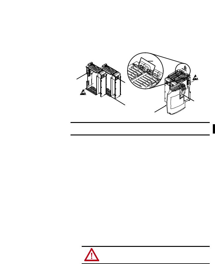
Follow this procedure to assemble the Compact I/O system.
3
4
2
1
6
1
5
IMPORTANT To reduce the effects of electrical noise, install the 1769-IT6 module at least two slots away from the AC power supplies.
1.Disconnect power.
2.Check that the bus lever of the module to be installed is in the unlocked (fully right) position.
TIP |
If the module is being installed to the left of an existing module, |
|
check that the right-side adjacent module’s bus lever is in the |
|
unlocked (fully right) position. |
3.Use the upper and lower tongue-and-groove slots (1) to secure the modules together (or to a controller).
4.Move the module back along the tongue-and-groove slots until the bus connectors (2) line up with each other.
5.Push the bus lever back slightly to clear the positioning tab (3) by using your fingers or a small screwdriver.
6.To allow communication between the controller and module, move the bus lever fully to the left (4) until it clicks.
Be sure it is locked firmly in place.
ATTENTION: When attaching I/O modules, it is very important that the bus connectors are securely locked together to be sure of proper electrical connection.
7.Attach an end cap terminator (5) to the last module in the system by using the tongue-and-groove slots as before.
Rockwell Automation Publication 1769-UM004B-EN-P - March 2010 |
27 |
Chapter 3 Installation and Wiring
8. Lock the end cap bus terminator (6).
IMPORTANT A 1769-ECR or 1769-ECL right or left end cap respectively must be used to terminate the end of the bus.
Mounting
ATTENTION: During panel or DIN rail mounting of all devices, be sure that all debris (metal chips, wire strands) is kept from falling into the module. Debris that falls into the module could cause damage at powerup.
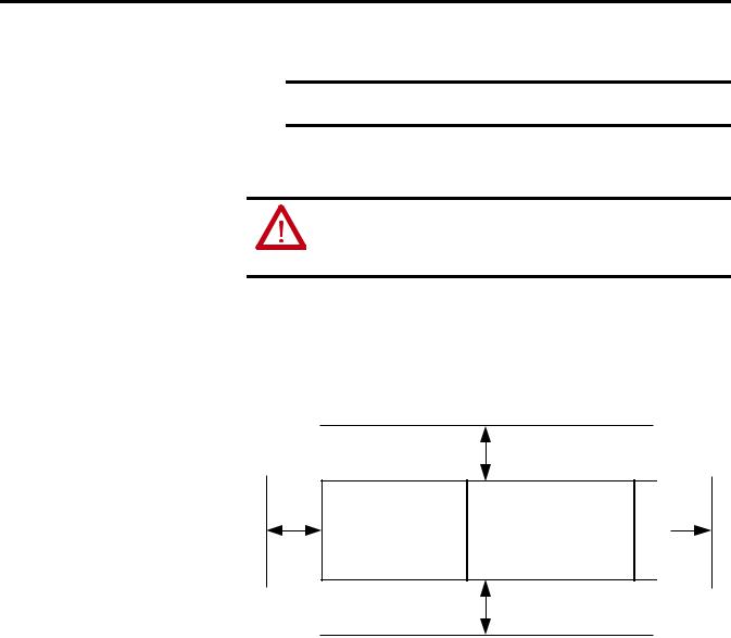
Minimum Spacing
Maintain spacing from enclosure walls, wireways, adjacent equipment, and so forth. Allow 50 mm (2 in.) of space on all sides for adequate ventilation, as shown below.
Side
Host Controller
Top
Compact I/O |
Compact I/O |
Compact I/O |
Compact I/O |
Compact I/O |
|
|
|
|
|
End Cap
Side
Bottom
Panel Mounting
Mount the module to a panel by using two screws per module. Use M4 or #8 panhead screws. Mounting screws are required on every module.
28 |
Rockwell Automation Publication 1769-UM004B-EN-P - March 2010 |
Installation and Wiring Chapter 3
Panel Mounting by Using the Dimensional Template
For more than 2 modules: (number of modules-1) X 35 mm (1,38 in.). |
|
35 |
|
|
|
|
28.5 |
|
||||||||||
|
|
|
|
|
|
|||||||||||||
Refer to host controller documentation for this dimension. |
|
|
|
|
|
|
|
|
|
|
|
|||||||
|
|
|
|
|
|
|
|
|
|
|
||||||||
|
|
|
|
|
(1.38) |
|
|
|
(1.12) |
|
||||||||
|
|
|
|
|
|
|
|
|
|
|
|
|
|
|||||
|
|
|
|
|
|
|
|
|
|
|
|
|
|
|
|
|
|
|
|
|
|
|
|
|
|
|
|
|
|
|
|
|
|
|
|
|
|
|
|
|
|
|
|
|
|
|
|
|
|
|
|
|
|
|
|
|
|
|
|
|
|
|
|
|
|
|
|
|
|
|
|
|
|
|
|
132
(5.197)
122.6±0.2
(4.826±0.008)
Important: All dimensions are in mm (inches). Hole spacing tolerance: ±0.04 mm (0.016 in.).
Host Controller |
Compact I/O |
Compact I/O |
Compact I/O |
Right End Cap |
Panel Mounting Procedure by Using Modules as a Template
The following procedure allows you to use the assembled modules as a template for drilling holes in the panel. If you have sophisticated panel mounting equipment, you can use the dimensional template provided on page 29. Due to module mounting hole tolerance, it is important to follow these procedures.
1.On a clean work surface, assemble no more than three modules.
2.Using the assembled modules as a template, carefully mark the center of all module-mounting holes on the panel.
3.Return the assembled modules to the clean work surface, including any previously mounted modules.
4.Drill and tap the mounting holes for the recommended M4 or #8 screw.
5.Place the modules back on the panel, and check for proper hole alignment.
6.Attach the modules to the panel by using the mounting screws.
TIP |
If mounting more modules, mount only the last one of this group |
|
and put the others aside. This reduces remounting time during |
|
drilling and tapping of the next group. |
7. Repeat steps 1…6 for any remaining modules.
DIN Rail Mounting
The module can be mounted by using either of these DIN rails:
•35 x 7.5 mm (EN 50 022 - 35 x 7.5)
•35 x 15 mm (EN 50 022 - 35 x 15)
Before mounting the module on a DIN rail, close the DIN rail latches. Press the DIN rail mounting area of the module against the DIN rail. The latches will momentarily open and lock into place.
Rockwell Automation Publication 1769-UM004B-EN-P - March 2010 |
29 |

Chapter 3 Installation and Wiring
Replace a Single Module within a System
The module can be replaced while the system is mounted to a panel (or DIN rail). Follow these steps in order.
1.Remove power.
See the important note on page 27.
2.On the module to be removed, remove the upper and lower mounting screws from the module (or open the DIN latches with screwdriver).
3.Move the bus lever to the right to disconnect (unlock) the bus.
4.On the right-side adjacent module, move its bus lever to the right (unlock) to disconnect it from the module to be removed.
5.Gently slide the disconnected module forward.
If you feel excessive resistance, check that the module has been disconnected from the bus, and that both mounting screws have been removed (or DIN latches opened).
TIP |
It may be necessary to rock the module slightly from front to back |
|
to remove it, or, in a panel-mounted system, to loosen the screws |
|
of adjacent modules. |
6.Before installing the replacement module, be sure that the bus lever on the module to be installed and on the right-side adjacent module or end cap are in the unlocked (fully right) position.
7.Slide the replacement module into the open slot.
8.Connect the modules together by locking (fully left) the bus levers on the replacement module and the right-side adjacent module.
9.Replace the mounting screws (or snap the module onto the DIN rail).
Field Wiring Connections |
Use these guidelines when making field wiring connections. |
System Wiring Guidelines
Consider these guidelines when wiring your system:
General Guidelines
•Power and input wiring must be in accordance with Class 1, Division 2 wiring methods, Article 501-4(b) of the National Electric Code, NFPA 70, and in accordance with the authority having jurisdiction.
•Channels are isolated from one another by ±10V DC maximum.
•Route field wiring away from any other wiring and as far as possible from sources of electrical noise, such as motors, transformers, contactors, and AC devices. As a general rule, allow at least 15.2 cm (6 in.) of separation for every 120V of power.
30 |
Rockwell Automation Publication 1769-UM004B-EN-P - March 2010 |
Loading...