


 Loading...
Installation Instructions
Compact 1769-OF4CI Isolated Analog
Output Module
Catalog Number 1769-OF4CI
Topic |
Page |
|
|
Important User Information |
2 |
|
|
About the Module |
4 |
|
|
System Assembly |
7 |
|
|
Mounting Expansion I/O |
8 |
|
|
Replacing a Single Module Within a System |
11 |
|
|
Module Spare/replacement Parts |
12 |
|
|
Grounding the Module |
12 |
|
|
I/O Memory Mapping |
17 |
|
|
Specifications |
22 |
|
|
Additional Resources |
2 |
|
|
2 Compact 1769-OF4CI Isolated Analog Output Module
Important User Information
Solid-state equipment has operational characteristics differing from those of electromechanical equipment. Safety Guidelines for the Application, Installation and Maintenance of Solid State Controls (Publication SGI-1.1 available from your local Rockwell Automation sales office or online at http://www.rockwellautomation.com/literature/) describes some important differences between solid-state equipment and hard-wired electromechanical devices. Because of this difference, and also because of the wide variety of uses for solid-state equipment, all persons responsible for applying this equipment must satisfy themselves that each intended application of this equipment is acceptable.
In no event will Rockwell Automation, Inc. be responsible or liable for indirect or consequential damages resulting from the use or application of this equipment.
The examples and diagrams in this manual are included solely for illustrative purposes. Because of the many variables and requirements associated with any particular installation, Rockwell Automation, Inc. cannot assume responsibility or liability for actual use based on the examples and diagrams.
No patent liability is assumed by Rockwell Automation, Inc. with respect to use of information, circuits, equipment, or software described in this manual.
Reproduction of the contents of this manual, in whole or in part, without written permission of Rockwell Automation, Inc., is prohibited.
Throughout this manual, when necessary, we use notes to make you aware of safety considerations.
WARNING: Identifies information about practices or circumstances that can cause an explosion in a hazardous environment, which may lead to personal injury or death, property damage, or economic loss.
ATTENTION: Identifies information about practices or circumstances that can lead to personal injury or death, property damage, or economic loss. Attentions help you identify a hazard, avoid a hazard and recognize the consequences.
SHOCK HAZARD: Labels may be on or inside the equipment, for example, drive or motor, to alert people that dangerous voltage may be present.
BURN HAZARD: Labels may be on or inside the equipment, for example, drive or motor, to alert people that surfaces may reach dangerous temperatures.
IMPORTANT Identifies information that is critical for successful application and understanding of the product.
Rockwell Automation Publication 1769-IN075B-EN-P - August 2010

Compact 1769-OF4CI Isolated Analog Output Module 3
North American Hazardous Location Approval
The following information applies |
Informations sur l’utilisation de cet |
||||||
when operating this equipment in |
équipement en environnements |
||||||
hazardous locations. |
dangereux. |
||||||
Products marked "CL I, DIV 2, GP A, B, C, D" are |
Les produits marqués "CL I, DIV 2, GP A, B, C, D" ne |
||||||
suitable for use in Class I Division 2 Groups A, B, C, |
conviennent qu'à une utilisation en environnements |
||||||
D, Hazardous Locations and nonhazardous |
de Classe I Division 2 Groupes A, B, C, D dangereux et |
||||||
locations only. Each product is supplied with |
non dangereux. Chaque produit est livré avec des |
||||||
markings on the rating nameplate indicating the |
marquages sur sa plaque d'identification qui indiquent |
||||||
hazardous location temperature code. When |
le code de température pour les environnements |
||||||
combining products within a system, the most |
dangereux. Lorsque plusieurs produits sont combinés |
||||||
adverse temperature code (lowest "T" number) may |
dans un système, le code de température le plus |
||||||
be used to help determine the overall temperature |
défavorable (code de température le plus faible) peut |
||||||
code of the system. Combinations of equipment in |
être utilisé pour déterminer le code de température |
||||||
your system are subject to investigation by the |
global du système. Les combinaisons d'équipements |
||||||
local Authority Having Jurisdiction at the time of |
dans le système sont sujettes à inspection par les |
||||||
installation. |
autorités locales qualifiées au moment de |
||||||
|
|
|
|
l'installation. |
|||
|
|
|
|
|
|
|
|
|
|
|
WARNING: |
|
|
|
AVERTISSEMENT: |
|
|
|
Explosion Hazard - |
|
|
|
Risque d’Explosion – |
|
|
|
• Do not disconnect equipment |
|
|
|
• Couper le courant ou s'assurer que |
|
|
|
|||||
|
|
|
unless power has been removed |
|
|
|
l'environnement est classé non |
|
|
|
or the area is known to be |
|
|
|
dangereux avant de débrancher |
|
|
|
nonhazardous. |
|
|
|
l'équipement. |
|
|
|
• Do not disconnect connections to |
|
|
|
• Couper le courant ou s'assurer que |
|
|
|
this equipment unless power has |
|
|
|
l'environnement est classé non |
|
|
|
been removed or the area is |
|
|
|
dangereux avant de débrancher les |
|
|
|
known to be nonhazardous. |
|
|
|
connecteurs. Fixer tous les |
|
|
|
Secure any external connections |
|
|
|
connecteurs externes reliés à cet |
|
|
|
that mate to this equipment by |
|
|
|
équipement à l'aide de vis, loquets |
|
|
|
using screws, sliding latches, |
|
|
|
coulissants, connecteurs filetés ou |
|
|
|
threaded connectors, or other |
|
|
|
autres moyens fournis avec ce |
|
|
|
means provided with this product. |
|
|
|
produit. |
|
|
|
• Substitution of components may |
|
|
|
• La substitution de composants peut |
|
|
|
impair suitability for Class I, |
|
|
|
rendre cet équipement inadapté à |
|
|
|
Division 2. |
|
|
|
une utilisation en environnement de |
|
|
|
• If this product contains batteries, |
|
|
|
Classe I, Division 2. |
|
|
|
they must only be changed in an |
|
|
|
• S'assurer que l'environnement est |
|
|
|
area known to be nonhazardous. |
|
|
|
classé non dangereux avant de |
|
|
|
|
|
|
|
changer les piles. |
|
|
|
|
|
|
|
|
Rockwell Automation Publication 1769-IN075B-EN-P - August 2010
4 Compact 1769-OF4CI Isolated Analog Output Module
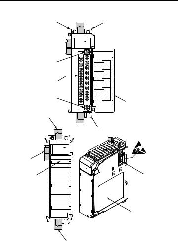
About the Module
1
10a
10
10b
8a
7a
OK
Analog
5a
9
2a
OK  3
3
Analog
DANGER
Do Not Remove RTB Under Power
Unless Area is Non-Hazardous
N/C
N/C
I out 0 -
I out 0 +
N/C
N/C
I out 1 -
I out 1 +
N/C
N/C
I out 2 -
I out 2 +
N/C
N/C
I out 3 -
I out 3 +
N/C
N/C
Ensure Adjacent
Bus Lever is Unlatched/Latched
Before/After
Removing/Inserting Module
1769-OF4CI
2b
 7a
7a
4
5b
6
7b
 7b
7b
8b
Rockwell Automation Publication 1769-IN075B-EN-P - August 2010

Compact 1769-OF4CI Isolated Analog Output Module 5
Item |
Description |
Item |
Description |
|
|
|
|
1 |
Bus lever (with locking function) |
7a |
Upper tongue-and-groove slots |
|
|
|
|
2a |
Upper panel mounting tab |
7b |
Lower tongue-and-groove slots |
|
|
|
|
2b |
Lower panel mounting tab |
8a |
Upper DIN rail latch |
|
|
|
|
3 |
Module status LED |
8b |
Lower DIN rail latch |
|
|
|
|
4 |
Module door with terminal |
9 |
Write-on label (user ID tag) |
|
identification label |
|
|
|
|
|
|
5a |
Movable bus connector with |
10 |
Removable terminal block (RTB) with |
|
female pins |
|
finger-safe cover |
|
|
|
|
5b |
Stationary bus connector with |
10a |
RTB upper retaining screw |
|
male pins |
|
|
|
|
|
|
6 |
Nameplate label |
10b |
RTB lower retaining screw |
|
|
|
|
Rockwell Automation Publication 1769-IN075B-EN-P - August 2010
6 Compact 1769-OF4CI Isolated Analog Output Module
Module Installation
Compact I/O is suitable for use in an industrial environment when installed in accordance with these instructions.
Prevent Electrostatic Discharge
ATTENTION: Electrostatic discharge can damage integrated circuits or semiconductors if you touch bus connector pins or the terminal block. Follow these guidelines when you handle the module:
•Touch a grounded object to discharge static potential.
•Wear an approved wrist-strap grounding device.
•Do not touch the bus connector or connector pins.
•Do not touch circuit components inside the module.
•Use a static-safe work station, if available.
•When not in use, keep the module in its static-shield box.
Remove Power
ATTENTION: Remove power before removing or inserting this module. When you remove or insert a module with power applied, an electrical arc may occur. An electrical arc can cause personal injury or property damage by:
•sending an erroneous signal to your system’s field devices, causing unintended machine motion.
•causing an explosion in a hazardous environment. Electrical arcing causes excessive wear to contacts on both the
module and its mating connector. Worn contacts may create electrical resistance.
Rockwell Automation Publication 1769-IN075B-EN-P - August 2010

Compact 1769-OF4CI Isolated Analog Output Module 7
System Assembly
The module can be attached to the controller or an adjacent I/O module before or after mounting.
•For mounting instructions, see Panel Mounting on page 10, or DIN Rail Mounting on page 11.
•To work with a system that is already mounted, see Replacing a Single
Module Within a System on page 11.
The following procedure shows you how to assemble the Compact I/O system.
|
|
|
3 |
|
|
|
4 |
2 |
|
1 |
|
|
|
|
|
|
|
1 |
6 |
|
|
|
|
|
|
|
5 |
Item |
Description |
Item |
Description |
1 |
Tongue-and-groove slots |
4 |
Bus lever |
2 |
Bus connectors |
5 |
End-cap terminator |
3 |
Positioning tab |
6 |
End-cap bus terminator |
1.Disconnect power.
2.Check that the bus lever of the module to be installed is in the unlocked (fully right) position.
Rockwell Automation Publication 1769-IN075B-EN-P - August 2010
8Compact 1769-OF4CI Isolated Analog Output Module
3.Use the upper and lower tongue-and-groove slots (1) to secure the modules together (or to a controller).
4.Move the module back along the tongue-and-groove slots until the bus connectors (2) line up with each other.
5.Push the bus lever back slightly to clear the positioning tab (3). Use your fingers or a small screwdriver.
6.To allow communication between the controller and module, move the bus lever fully to the left (4) until it clicks. Make sure it is locked firmly in place.
ATTENTION: When attaching I/O modules, it is very important that the bus connectors are securely locked together for proper electrical connection.
7.Attach an end cap terminator (5) to the last module in the system by using the tongue-and-groove slots as before.
8.Lock the end cap bus terminator (6).
IMPORTANT A 1769-ECR or 1769-ECL right or left end cap must be used to terminate the end of the serial communication bus.
Mounting Expansion I/O
ATTENTION: During panel or DIN rail mounting of all devices, be sure that all debris, such as metal chips or wire strands, is kept from falling into the module. Debris that falls into the module could cause damage on power up.
Rockwell Automation Publication 1769-IN075B-EN-P - August 2010
Compact 1769-OF4CI Isolated Analog Output Module 9
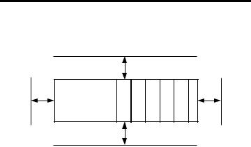
Minimum Spacing
Maintain spacing from enclosure walls, wireways, adjacent equipment, etc. Allow
50 mm (2 in.) of space on all sides for adequate ventilation.
1
6
4
2 |
2 |
2 |
2 |
2 |
3 |
4
5
Item |
Description |
Item |
Description |
|
|
|
|
1 |
Top |
4 |
Side |
|
|
|
|
2 |
Compact I/O modules |
5 |
Bottom |
|
|
|
|
3 |
End cap |
6 |
Host controller |
|
|
|
|
Rockwell Automation Publication 1769-IN075B-EN-P - August 2010
Loading...