


 Loading...
Quick Start
CompactLogix 5370 L1 Controllers
Catalog Numbers 1769-L16ER-BB1B, 1769-L18ER-BB1B, 1769-L18ERM-BB1B
Important User Information
Solid-state equipment has operational characteristics differing from those of electromechanical equipment. Safety Guidelines for the Application, Installation and Maintenance of Solid State Controls (publication SGI-1.1 available from your local Rockwell Automation sales office or online at http://www.rockwellautomation.com/literature/) describes some important differences between solid-state equipment and hard-wired electromechanical devices. Because of this difference, and also because of the wide variety of uses for solid-state equipment, all persons responsible for applying this equipment must satisfy themselves that each intended application of this equipment is acceptable.
In no event will Rockwell Automation, Inc. be responsible or liable for indirect or consequential damages resulting from the use or application of this equipment.
The examples and diagrams in this manual are included solely for illustrative purposes. Because of the many variables and requirements associated with any particular installation, Rockwell Automation, Inc. cannot assume responsibility or liability for actual use based on the examples and diagrams.December
No patent liability is assumed by Rockwell Automation, Inc. with respect to use of information, circuits, equipment, or software described in this manual.
Reproduction of the contents of this manual, in whole or in part, without written permission of Rockwell Automation, Inc., is prohibited.
Throughout this manual, when necessary, we use notes to make you aware of safety considerations.
WARNING: Identifies information about practices or circumstances that can cause an explosion in a hazardous environment, which may lead to personal injury or death, property damage, or economic loss.
ATTENTION: Identifies information about practices or circumstances that can lead to personal injury or death, property damage, or economic loss. Attentions help you identify a hazard, avoid a hazard, and recognize the consequence.
SHOCK HAZARD: Labels may be on or inside the equipment, for example, a drive or motor, to alert people that dangerous voltage may be present.
BURN HAZARD: Labels may be on or inside the equipment, for example, a drive or motor, to alert people that surfaces may reach dangerous temperatures.
IMPORTANT Identifies information that is critical for successful application and understanding of the product.
Allen-Bradley, CompactLogix, ControlFLASH, FactoryTalk, FLEX, Integrated Architecture, Kinetix, Logix5000, PanelView, POINT I/O, PowerFlex, Rockwell Software, Rockwell Automation, RSLinx, RSLogix, Stratix 6000, Studio 5000, and TechConnect are trademarks of Rockwell Automation, Inc.
Trademarks not belonging to Rockwell Automation are property of their respective companies.
Where to Start
Follow the path that matches your hardware and network configuration.
Prepare the CompactLogix 5370 L1
Controller Hardware
Required
page 17
Prepare the Computer and Load
Controller Firmware
Required
page 31
Optional
For more information on using each optional device, see Table 1 on page 12.
page 45
Optional
Create a Logix Designer Project
Required
page 51
Rockwell Automation Publication IASIMP-QS024B-EN-P - December 2012 |
3 |

Where to Start
How Hardware is Connected
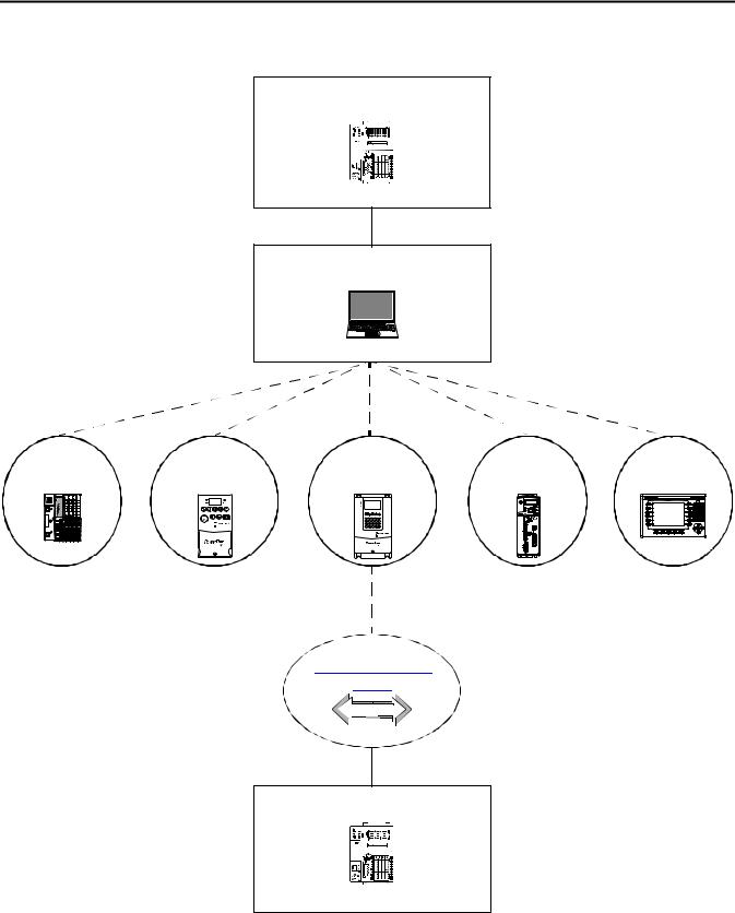
This quick start, in use with the additional quick starts listed in Table 1 on page 12, describes a CompactLogix™ 5370 L1 control system as shown in Figure 1.
Figure 1 - CompactLogix 5370 L1 Controller in a Star Network Topology
Computer |
CompactLogix 5370 L1 |
|
Control System |
||
|
Star Network Topology
Stratix 6000™Switch
PowerFlex 40 Drive with 22-COMM-E Adapter
|
|
PORT |
|
|
|
MOD |
PowerFlex 70 Drive with |
6 |
5 |
NET B |
|
NET A |
|||
8 |
7 |
|
|
|
|
|
STS |
|
|
|
20-COMM-E Adapter |
4 |
3 |
|
|
2 |
1 |
|
|
|
|
|
|
|
|
|
|
|
|
|
|
|
|
|
|
|
|
|
|
|
|
|
|
|
|
|
|
|
|
|
|
|
|
|
|
|
|
|
|
|
|
|
|
|
|
|
|
|
|
|
|
|
|
|
|
|
|
|
|
|
|
|
|
|
|
|
|
|
|
|
|
|
|
|
|
|
|
|
|
|
|
|
|
|
|
|
|
|
|
|
|
|
|
|
|
|
|
|
|
|
|
|
|
|
|
|
|
|
|
|
|
|
|
|
|
|
|
|
|
|
|
|
|
|
|
|
|
|
|
|
|
|
|
|
|
|
|
|
|
|
|
|
|
|
|
|
|
|
|
|
|
|
|
|
|
|
|
|
|
|
|
|
|
|
|
|
|
PanelView Plus Terminal with Built-in |
Kinetix 350 Drive |
Distributed POINT I/O Modules with |
|||||||||||||||||||||||||
|
|
|
EtherNet/IP Port |
|
|
|
|
|
|
|
|
|
|
1734-AENT Adapter |
|||||||||||||
Application Configuration
4 |
Rockwell Automation Publication IASIMP-QS024B-EN-P - December 2012 |
Where to Start
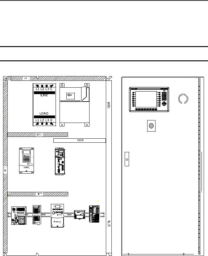
Sample Panel Layout
The sample panel layout shows the orientation of an example CompactLogix 5370 L1 control system using an EtherNet/IP network.
IMPORTANT The graphic below is an example panel layout. The specific layout of CompactLogix 5370 L1 control systems varies by application.
|
|
PanelView Plus Terminal |
|
AC Line Filter |
|
|
|
|
|
Line Interface |
Through-the-door |
|
|
Disconnect |
|
|
|
Module |
|
|
|
|
|
|
|
E-stop Push Button |
|
PORT |
|
|
|
MOD |
|
|
|
NET B |
|
|
|
NET A |
|
|
|
STS |
|
|
|
PowerFlex 70 Drive |
Kinetix 350 Drive |
|
|
Ethernet Switch |
|
|
|
CompactLogix 5370 L1 |
PowerFlex 40 |
Distributed POINT I/O |
|
Control System |
Drive |
Modules |
|
|
Rockwell Automation Publication IASIMP-QS024B-EN-P - December 2012 |
5 |
|

Where to Start
Notes:
6 |
Rockwell Automation Publication IASIMP-QS024B-EN-P - December 2012 |

|
|
Table of Contents |
Preface |
About the CompactLogix 5370 L1 Controllers . . . . . . . |
. . . . . . . . . . . . . . 10 |
|
Choose to Integrate Optional Devices . . . . . . . . . . . . . . . |
. . . . . . . . . . . . . . 12 |
|
Studio 5000 Environment . . . . . . . . . . . . . . . . . . . . . . . . . . . |
. . . . . . . . . . . . . 13 |
|
Required Software . . . . . . . . . . . . . . . . . . . . . . . . . . . . . . . . . . |
. . . . . . . . . . . . . 14 |
|
Parts List . . . . . . . . . . . . . . . . . . . . . . . . . . . . . . . . . . . . . . . . . . . |
. . . . . . . . . . . . . 15 |
|
Additional Resources . . . . . . . . . . . . . . . . . . . . . . . . . . . . . . . . |
. . . . . . . . . . . . . 15 |
Prepare the CompactLogix 5370 L1
Controller Hardware
Chapter 1
What You Need . . . . . . . . . . . . . . . . . . . . . . . . . . . . . . . . . . . . . . . . . . . . . . . . . 17
Follow These Steps . . . . . . . . . . . . . . . . . . . . . . . . . . . . . . . . . . . . . . . . . . . . . . . 18
Install the EtherNet/IP Network . . . . . . . . . . . . . . . . . . . . . . . . . . . . . . . . . . 19 Install the Secure Digital Card . . . . . . . . . . . . . . . . . . . . . . . . . . . . . . . . . . . . 20
Mount the Controller . . . . . . . . . . . . . . . . . . . . . . . . . . . . . . . . . . . . . . . . . . . . 22
Install the Local Expansion Module. . . . . . . . . . . . . . . . . . . . . . . . . . . . . . . . 23 Wire Power to the Controller . . . . . . . . . . . . . . . . . . . . . . . . . . . . . . . . . . . . . 25
Make Network Connections . . . . . . . . . . . . . . . . . . . . . . . . . . . . . . . . . . . . . . 28
Make a USB Connection . . . . . . . . . . . . . . . . . . . . . . . . . . . . . . . . . . . . . 28 Make EtherNet/IP Network Connections. . . . . . . . . . . . . . . . . . . . . . 29
Prepare the Computer and Load
Controller Firmware
Chapter 2
Before You Begin . . . . . . . . . . . . . . . . . . . . . . . . . . . . . . . . . . . . . . . . . . . . . . . . 31 What You Need . . . . . . . . . . . . . . . . . . . . . . . . . . . . . . . . . . . . . . . . . . . . . . . . . 32 Follow These Steps . . . . . . . . . . . . . . . . . . . . . . . . . . . . . . . . . . . . . . . . . . . . . . . 33 Install the Studio 5000 Environment . . . . . . . . . . . . . . . . . . . . . . . . . . . . . . 34 Automatic Installation of ControlFLASH Software. . . . . . . . . . . . . . . . . 36 Configure an EtherNet/IP Driver in RSLinx Classic Software . . . . . . . 36 Set the IP Address for the Computer. . . . . . . . . . . . . . . . . . . . . . . . . . . . . . . 38 Load the Controller Firmware . . . . . . . . . . . . . . . . . . . . . . . . . . . . . . . . . . . . 41 Install Additional Software - Optional . . . . . . . . . . . . . . . . . . . . . . . . . . . . . 44
Chapter 3
Configure the EtherNet/IP Network Before You Begin . . . . . . . . . . . . . . . . . . . . . . . . . . . . . . . . . . . . . . . . . . . . . . . . 46 What You Need . . . . . . . . . . . . . . . . . . . . . . . . . . . . . . . . . . . . . . . . . . . . . . . . . 47 Assign an IP Address to the Controller over a USB Connection. . . . . . 48
Rockwell Automation Publication IASIMP-QS024B-EN-P - December 2012 |
7 |

Table of Contents |
|
|
|
Chapter 4 |
|
Create a Logix Designer Project |
Before You Begin. . . . . . . . . . . . . . . . . . . . . . . . . . . . . . . . . . . . . . . . . . . . . . . . . |
52 |
|
What You Need. . . . . . . . . . . . . . . . . . . . . . . . . . . . . . . . . . . . . . . . . . . . . . . . . . |
52 |
|
Follow These Steps . . . . . . . . . . . . . . . . . . . . . . . . . . . . . . . . . . . . . . . . . . . . . . . |
53 |
|
Create a Project . . . . . . . . . . . . . . . . . . . . . . . . . . . . . . . . . . . . . . . . . . . . . . . . . . |
54 |
|
Configure the Controller . . . . . . . . . . . . . . . . . . . . . . . . . . . . . . . . . . . . . . . . . |
55 |
|
Add a Local Expansion Module. . . . . . . . . . . . . . . . . . . . . . . . . . . . . . . . . . . . |
58 |
|
Add Ladder Logic to Test the Local Expansion Module. . . . . . . . . . . . . . |
60 |
|
Download to the Controller. . . . . . . . . . . . . . . . . . . . . . . . . . . . . . . . . . . . . . . |
63 |
Understanding Other Application
Options
Index
Appendix A
DLR Network Topology . . . . . . . . . . . . . . . . . . . . . . . . . . . . . . . . . . . . . . . . . . 66
Follow These Steps . . . . . . . . . . . . . . . . . . . . . . . . . . . . . . . . . . . . . . . . . . . 67 Integrated Motion on the EtherNet/IP Network. . . . . . . . . . . . . . . . . . . . 68
Follow These Steps . . . . . . . . . . . . . . . . . . . . . . . . . . . . . . . . . . . . . . . . . . . 68
. . . . . . . . . . . . . . . . . . . . . . . . . . . . . . . . . . . . . . . . . . . . . . . . . . . . . . . . . . . . . . . . . .69
8 |
Rockwell Automation Publication IASIMP-QS024B-EN-P - December 2012 |

Preface
This quick start describes how to use CompactLogix 5370 L1 controllers to install a simple CompactLogix 5370 L1 control system and execute a task with a local 1734 POINT I/O output module. The programming examples included are not complex, and offer solutions to verify that devices are functioning and communicating properly.
IMPORTANT Consider the following points:
•A typical CompactLogix 5370 L1 control system includes more components than listed in this quick start. For example, you can use 1734 POINT I/O modules over an EtherNet/IP network in a CompactLogix 5370 L1 control system. Other quick starts describe how to use additional components with your control system.
For a list of quick starts describing how to use other components in Logix5000™ control systems, see Choose to Integrate Optional Devices on page 12.
•Not all tasks described in this quick start are required to complete the final task, that is, use ladder logic to test a 1769-OB16 output module as described beginning on page 51. For example, you do not need a DeviceNet configuration file to test the module.
We expect that you might attempt to complete additional tasks with your control system by using the publications listed on page 12. When you use those publications, some assumptions are made. For example, if you use a PanelView Plus terminal over an EtherNet/IP network in a CompactLogix 5370 L3 control system, you must have already created project and assigned an IP address to the controller.
If you complete all of the tasks described in this quick start, you can easily complete the tasks described in the publications listed on page 12.
The following topics are described in this quick start:
•Installing hardware for a basic CompactLogix 5370 L1 control system
•Installing software required for the basic CompactLogix 5370 L1 control system
Rockwell Automation Publication IASIMP-QS024B-EN-P - December 2012 |
9 |

Preface
• Configuring an EtherNet/IP network
IMPORTANT You are not required to install nor configure an EtherNet/IP network to complete the tasks described in this quick start. However, before you can complete the tasks described in some of the publications listed on page 12, you must first install an EtherNet/IP network.
For example, Chapter 4, on Create a Logix Designer Project on page 51 describes how to use ladder logic to test a 1734-OB4E output module. The test is completed by using the output module in a local expansion slot in the CompactLogix 5370 L1 control system and does not require use of a 1783-EMS08T Stratix 6000 managed switch because it can be done via a USB connection to the controller.
If you use 1734 POINT I/O modules over an EtherNet/IP network in your CompactLogix 5370 L1 control system, as described in the Logix5000 Control Systems: POINT I/O over an EtherNet/IP Network Quick Start, publication IASIMP-QS027, you must install and configure an EtherNet/IP network.
Completing all of the tasks described in this quick start will assist you when attempting to complete the tasks in some other quick starts, such as publication IASIMP-QS027.
• Creating a Logix Designer project
About the CompactLogix 5370 L1 Controllers
These CompactLogix 5370 L1 controllers are available:
•1769-L16ER-BB1B
•1769-L18ER-BB1B
•1769-L18ERM-BB1B
IMPORTANT The tasks described in this publication use a 1769-L18ERM-BB1B controller.
10 |
Rockwell Automation Publication IASIMP-QS024B-EN-P - December 2012 |
Preface
These features are available on CompactLogix 5370 L1 controllers:
•Embedded 24V DC input nonisolated power supply
•Secure Digital (SD) card for nonvolatile memory storage
•Network connections:
–USB (single port)
–Support for EtherNet/IP networkOption to use the controller in device-level ring (DLR), linear, and star topologies on EtherNet/IP networks
•I/O module options:
–Sixteen embedded 24V DC digital input points
–Sixteen embedded 24V DC digital output points
–1734 POINT I/O modules as local expansion module
–Control of distributed I/O modules over an EtherNet/IP network
•Support for Integrated Motion on the EtherNet/IP network with the 1769-L18ERM- BB1B controller only.
•For more information on using the 1769-L18ERM-BB1B controller in an application that includes Integrated Motion on the EtherNet/IP network, see Appendix A, Understanding Other Application Options on page 65.
This graphic shows an example CompactLogix 5370 L1 control system.


 00:00:BC:2E:69:F6
|
|
|
|
|
|
|
|
|
|
|
|
|
|
|
|
|
|
|
|
|
|
|
|
|
|
|
|
|
|
|
|
|
|
|
|
|
|
|
|
|
|
|
11 |
|
|
|
|
|
|
|
|
|
|
|
|
|
|
|
|
|
|
|
|
|
|
|
|
|
|
|
|
|
|
|
|
|
|
|
|
|
|
|
|
|
|
|
|
Rockwell Automation Publication IASIMP-QS024B-EN-P - December 2012 |
|||||||||||||||||||||||||||||||||||||||||||
Preface
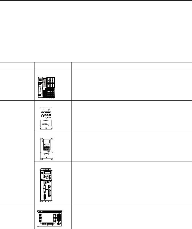
Choose to Integrate Optional Devices
This table describes additional optional devices and their related documentation that you might use in a CompactLogix 5370 L1 control system on an EtherNet/IP network.
You can view or download publications at http://www.rockwellautomation.com/literature/.
Table 1 - Devices in Logix5000 Control System
Device Type |
Product Line(1) |
Additional Resource with More Information |
Distributed I/O |
POINT I/O |
Logix5000 Control Systems: Connect POINT I/O Modules over an EtherNet/IP Network |
|
0 0 2 1734-AENTR |
Quick Start, publication IASIMP-QS027 |
|
POINT I O |
|
|
Link 1 |
|
|
Activity/ |
|
|
Status |
|
|
IP ADDRESS |
|
|
Link 2 |
|
|
Activity/ |
|
|
Status |
|
Drives |
PowerFlex40 |
Logix5000 Control Systems: Connect PowerFlex 40 Drives over an EtherNet/IP |
|
|
Network Quick Start, publication IASIMP-QS029 |
PowerFlex 70
PORT
MOD
NET B
NET A
Logix5000 Control Systems: Connect PowerFlex 70 Drives over an EtherNet/IP Network Quick Start, publication IASIMP-QS031
STS
Kinetix 350 |
Logix5000 Control Systems: Connect Kinetix 350 Drives over an EtherNet/IP Network |
|
Quick Start, publication IASIMP-QS032 |
HMI terminals |
PanelView Plus |
Logix5000 Control Systems: Connect PanelView Plus Terminals over an EtherNet/IP |
|
|
Network Quick Start, publication IASIMP-QS033 |
(1) You can use other I/O modules, drives, and HMI terminals in Logix5000 control systems. These product lines are used for example purposes.
12 |
Rockwell Automation Publication IASIMP-QS024B-EN-P - December 2012 |
Preface
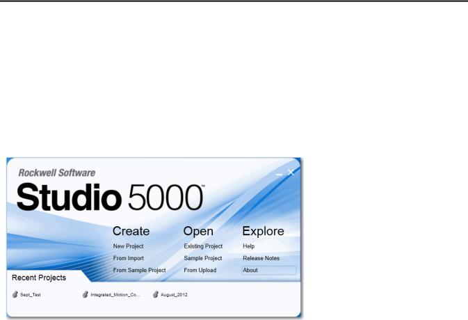
Studio 5000 Environment
The Studio 5000™ Engineering and Design Environment combines engineering and design elements into a common environment. The first element in the Studio 5000 environment is the Logix Designer application. The Logix Designer application is the rebranding of RSLogix™ 5000 software and will continue to be the product to program Logix5000 controllers for discrete, process, batch, motion, safety, and drive-based solutions.
The Studio 5000 environment is the foundation for the future of Rockwell Automation engineering design tools and capabilities. It is the one place for design engineers to develop all of the elements of their control system.
Rockwell Automation Publication IASIMP-QS024B-EN-P - December 2012 |
13 |

Preface
Required Software
Before attempting to complete any of the tasks described in this publication, verify that your computer meets the following operating system and service pack compatibility requirements:
•Microsoft Windows 7 Professional (64-bit) with Service Pack 1
•Microsoft Windows 7 Home Premium (64-bit) with Service Pack 1
•Microsoft Windows 7 Home Premium (32-bit) with Service Pack 1
•Microsoft Windows Server 2008 R2 Standard Edition with Service Pack 1
If your computer does not meet the operating system and service pack compatibility requirements, perform the necessary upgrades before continuing.
Table 2 lists the software used in this quick start. Specific software requirements are listed at the beginning of each chapter.
Table 2 - Software Used in This Quick Start
Software |
Minimum Version |
Required |
|
|
|
Studio 5000 |
21.00.00 |
Yes |
|
|
|
Logix Designer application |
21.00.00 |
Yes |
|
|
|
RSLinx® Classic |
3.51.00 or later |
Yes |
|
|
|
ControlFLASH™ |
Automatically installed with the Studio 5000 |
Yes |
|
environment |
|
|
|
|
14 |
Rockwell Automation Publication IASIMP-QS024B-EN-P - December 2012 |

Preface
Parts List
Table 3 lists the hardware used in this quick start. Specific hardware requirements are listed at the beginning of each chapter.
Table 3 - Parts Used with This Quick Start
Quantity |
Cat. No. |
Description |
|
|
|
1 or more |
N/A |
DIN rail (steel, not aluminum) |
|
|
|
1 |
One of the following: |
CompactLogix 5370 L1 controller |
|
• 1769-L16ER-BB1B |
The tasks described in this publication use a 1769-L18ERM-BB1B controller. |
|
|
|
|
• 1769-L18ER-BB1B |
|
|
• 1769-L18ERM-BB1B |
|
|
|
|
1 |
1606-XLP50E |
Switched-mode power supply |
|
|
|
1 |
1734-OB4E |
POINT I/O 8-point 24V DC electronically-fused output module |
|
|
|
1 |
1783-EMS08T |
Stratix 6000 Ethernet managed switch |
|
|
|
1 |
1585J-M8PBJM-2 |
RJ45-to-RJ45 patchcord Ethernet cables |
|
|
|
Additional Resources
These documents contain additional information concerning related products from Rockwell Automation.
Table 4 - Additional Resources
Resource |
Description |
|
|
CompactLogix 5370 Controllers User Manual, |
Describes how to design, install, operate, and troubleshoot a CompactLogix 5370 |
publication 1769-UM021 |
control system. |
|
|
Logix5000 Control Systems: Connect POINT I/O |
Describes basic steps required to include distributed POINT I/O modules over an |
Modules over an EtherNet/IP Network Quick |
EtherNet/IP network in a Logix5000 control system, including hardware, firmware, |
Start, publication IASIMP-QS027 |
and software considerations. |
|
|
Logix5000 Control Systems: Connect a |
Describes basic steps required to include PowerFlex 40 drives over an EtherNet/IP |
PowerFlex 40 Drive over a EtherNet/IP Network |
network in a Logix5000 control system, including hardware, firmware, and software |
Quick Start, publication IASIMP-QS029 |
considerations. |
|
|
Logix5000 Control Systems: Connect a |
Describes basic steps required to include PowerFlex 70 drives over an EtherNet/IP |
PowerFlex 70 Drive over an EtherNet/IP |
network in a Logix5000 control system, including hardware, firmware, and software |
Network Quick Start, publication IASIMP- |
considerations. |
QS031 |
|
|
|
Rockwell Automation Publication IASIMP-QS024B-EN-P - December 2012 |
15 |

Preface
Table 4 - Additional Resources
Resource |
Description |
|
|
Logix5000 Control Systems: Connect a Kinetix |
Describes basic steps required to include Kinetix 350 Multi-axis Servo drives over an |
350 Multi-axis Servo Drive System over an |
EtherNet/IP network in a Logix5000 control system, including hardware, firmware, |
EtherNet/IP Network Quick Start, publication |
and software considerations. |
IASIMP-QS032 |
|
|
|
Logix5000 Control Systems: Connect a |
Describes basic steps required to include PanelView Plus terminals over an EtherNet/IP |
PanelView Plus Terminal over an EtherNet/IP |
network in a Logix5000 control system, including hardware, firmware, and software |
Network Quick Start, publication IASIMP- |
considerations. |
QS033 |
|
|
|
ControlFLASH Firmware Upgrade Kit, |
Provides details regarding the installation of ControlFLASH software and execution of |
publication 1756-QS105 |
firmware upgrades. |
|
|
EtherNet/IP Modules in Logix5000 Control |
Describes how to install, configure, and operate EtherNet/IP modules. |
Systems, publication ENET-UM001 |
|
|
|
EtherNet/IP Media Planning and Installation |
Describes how to design and install an EtherNet/IP network |
Manual, ODVA publication |
|
Click here to access the publication |
|
|
|
Industrial Automation Wiring and Grounding |
Provides general guidelines for installing a Rockwell Automation® industrial system. |
Guidelines, publication 1770-4.1 |
|
|
|
Product Certifications website, http:// |
Provides declarations of conformity, certificates, and other certification details. |
www.ab.com |
|
|
|
You can view or download publications at http://www.rockwellautomation.com/literature/. To order paper copies of technical documentation, contact your local Allen-Bradley distributor or Rockwell Automation sales representative.
16 |
Rockwell Automation Publication IASIMP-QS024B-EN-P - December 2012 |

Chapter 1
Prepare the CompactLogix 5370 L1 Controller Hardware
This chapter describes how to install the hardware needed for your CompactLogix 5370 L1 control system.
What You Need
Table 5 lists the hardware components used in this chapter.
Table 5 - Parts Used with This Quick Start
Quantity |
Cat. No. |
Description |
|
|
|
1 or more |
N/A |
DIN rail (steel, not aluminum) |
|
|
|
1 |
One of the following: |
CompactLogix 5370 L1 controller |
|
• 1769-L16ER-BB1B |
The tasks described in this publication use a 1769-L18ERM-BB1B controller. |
|
|
|
|
• 1769-L18ER-BB1B |
|
|
• 1769-L18ERM-BB1B |
|
|
|
|
1 |
1606-XLP50E |
NEC Class 2/SELV switched-mode power supply |
|
|
|
1 |
1734-OB4E |
POINT I/O 8-point 24V DC electronically-fused output module |
|
|
|
1 |
1783-EMS08T |
Stratix 6000 Ethernet managed switch |
|
|
|
1 |
1585J-M8PBJM-2 |
RJ45-to-RJ45 patchcord Ethernet cables |
|
|
|
Rockwell Automation Publication IASIMP-QS024B-EN-P - December 2012 |
17 |
Chapter 1 Prepare the CompactLogix 5370 L1 Controller Hardware
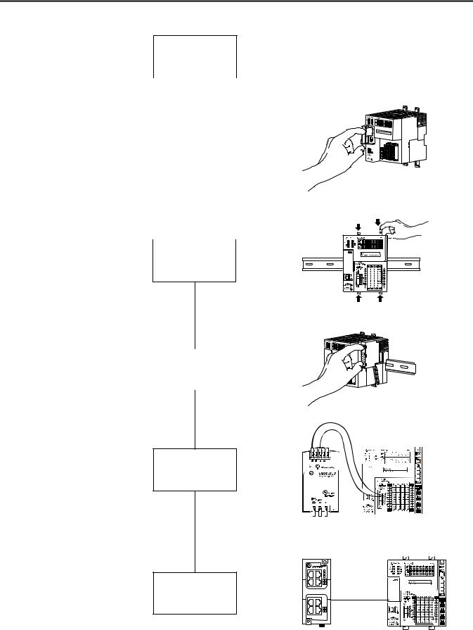
Follow These Steps
Install the
EtherNet/IP page 19
Network
|
|
|
|
|
|
|
|
|
|
|
|
|
|
|
|
|
|
|
|
|
|
|
|
|
|
|
|
|
|
|
|
|
|
|
|
|
Install the Secure |
|
|
|
|
|
|
|
|
|
|
|
page 20 |
|
|
|
|
|
|
||||
|
Digital Card |
|
|
|
|
|
|
||||
|
|
|
|
|
|
|
|
|
|
||
|
|
|
|
|
|
|
|
|
|
|
|
|
|
|
|
|
|
|
|
|
|
|
|
|
|
|
|
|
|
|
|
|
|
|
|
|
|
|
|
|
|
|
|
|
|
|
|
|
|
|
|
|
|
|
|
|
|
|
|
|
|
|
|
|
|
|
|
|
|
|
|
Mount the |
page 22 |
|
|
|
|
|
|
|
|
|
|
|
|
|
|
|
|
|
|
|
|
|
|
|
|
|
|
|
|
|
|
||
Controller |
|
|
|
|
|
|
|
|
|
|
|
|
|
|
|
|
Install the Local |
page 23 |
|
Expansion Module |
||
|
||
|
|
Wire Power to |
|
ok |
DC ok |
|
|
DC 24-28V |
50W max. |
the Controller |
page 25 |
DC |
|
28V |
00:00:BC:2E:69:F6 |
||
|
|
24- |
|
|
|
|
NEC Class 2 |
|
|
|
Power Supply |
Make Network |
8 |
7 |
|
6 |
5 |
00:00:BC:2E:69:F6 |
|
Connections |
page 28 |
|
|
|
|
|
|
|
4 |
3 |
|
|
2 |
1 |
|
18 |
Rockwell Automation Publication IASIMP-QS024B-EN-P - December 2012 |
|
|
|
|
|
|
|
|
|
|

Prepare the CompactLogix 5370 L1 Controller Hardware Chapter 1
Install the EtherNet/IP Network
You are not required to install an EtherNet/IP network to complete the tasks described in this quick start. You can complete the tasks via a USB connection to the CompactLogix 5370 L1 controller. However, we recommend that you install an EtherNet/IP network.
You will likely complete some tasks described in the publications listed on page 12. If you install an EtherNet/IP network when using this quick start, you will complete the tasks described in the publications listed on page 12 more easily.
For information on installing an EtherNet/IP network, see the publications listed in the following table.
Network |
Publication Title |
Publication Number |
|
|
|
EtherNet/IP |
EtherNet/IP Media Planning and Installation Manual |
Publication maintained and made available |
|
|
by ODVA |
|
|
Click here to access the publication |
|
|
|
|
Ethernet Design Considerations Reference Manual |
ENET-RM002 |
|
|
|
|
Stratix 6000 Ethernet Managed Switches Installation Instructions |
1783-IN004 |
|
|
|
|
Stratix 6000 Ethernet Managed Switch User Manual |
1783-UM001 |
|
|
|
The publications listed previously describe how to install the communication network and not how to connect your controller to the network. Make Network Connections on page 28 describes how to connect your controller to the network.
Rockwell Automation Publication IASIMP-QS024B-EN-P - December 2012 |
19 |
Chapter 1 Prepare the CompactLogix 5370 L1 Controller Hardware
Install the Secure Digital Card
The SD card provides nonvolatile storage for the CompactLogix 5370 L1 controller. You can store Logix Designer projects to an SD card or load a Logix Designer project from an SD card.
The following SD cards are available for use with your CompactLogix 5370 L1 controller:
•1784-SD1 card - 1 GB of memory
•1784-SD2 card - 2 GB of memory
The CompactLogix 5370 L1 controllers ship from the factory with the 1784-SD1 SD card installed.
Complete these steps to re-install an SD card that has been removed from the controller back into the controller or if installing a new SD card into the controller.
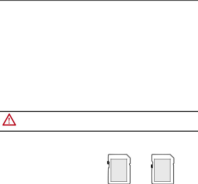
WARNING: When you insert or remove the SD card while power is on, an electrical arc can occur. This could cause an explosion in hazardous location installations.
Be sure that power is removed or the area is nonhazardous before proceeding.
1.Verify that the SD card is locked or unlocked according to your preference. Consider these points when
deciding to lock the card before |
|
|
installation: |
Unlocked |
Locked |
•If the card is unlocked, the controller can write data to it or read data from it.
•If the card is locked, the controller can only read data from it.
20 |
Rockwell Automation Publication IASIMP-QS024B-EN-P - December 2012 |
Prepare the CompactLogix 5370 L1 Controller Hardware Chapter 1
2. Open the door for the SD card.
3. Insert the SD card into the SD card slot.
You can install the SD card in one orientation only. The beveled corner should be at the top. An orientation logo is printed on the card.
If you feel resistance when inserting the SD card, pull it out and change the orientation.
4.Gently press the card until it clicks into place.
5.Close the SD card door.
Rockwell Automation Publication IASIMP-QS024B-EN-P - December 2012 |
21 |
Chapter 1 Prepare the CompactLogix 5370 L1 Controller Hardware
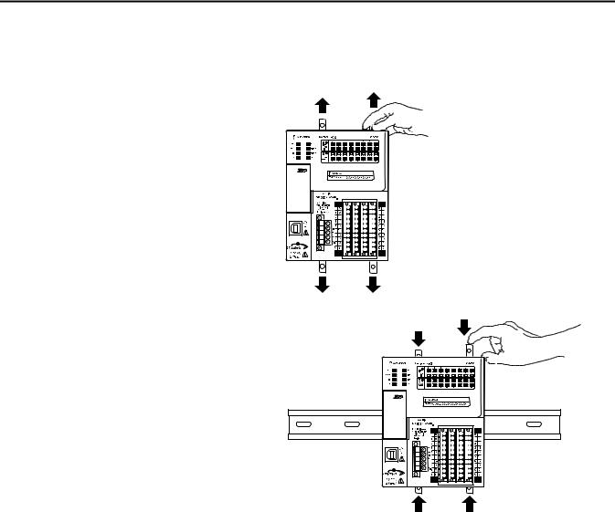
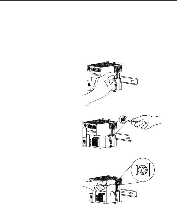
Mount the Controller
1. Pull the locking tabs out.
2.Slide the controller into position on the DIN rail and push the locking tabs in.
3.Make sure the protective covering on the right side of the controller is removed.
The protective covering must be removed to install a local expansion module, as described beginning on page 23.
22 |
Rockwell Automation Publication IASIMP-QS024B-EN-P - December 2012 |
Prepare the CompactLogix 5370 L1 Controller Hardware Chapter 1
Install the Local Expansion Module
This quick start uses a 1734-OB4E POINT I/O output module in a local expansion module slot.
1.Make sure the DIN rail locking screw in the mounting base, for example, the 1734-TB mounting base, is in the vertical position.
2. Align the tongue and groove slots of the mounting base to the slots on the right side of the controller and push it back until it seats on the DIN rail.
3. Use a small-bladed screwdriver to rotate the DIN rail locking screw to a horizontal position, locking the mounting base in place.
4. Set the key position on the mounting base before installing the 1734-OB4E module.
This example shows position 1.
5. Make sure the output module’s key position matches the position used on the mounting base.
Rockwell Automation Publication IASIMP-QS024B-EN-P - December 2012 |
23 |
Loading...