


 Loading...
Installation Instructions
1769-L31 CompactLogix Controller
Catalog Number 1769-L31
Topic |
Page |
|
|
|
|
Important User Information |
2 |
|
|
|
|
Environment and Enclosure Information |
3 |
|
|
|
|
Prevent Electrostatic Discharge |
4 |
|
|
|
|
North American Hazardous Location Approval |
5 |
|
|
|
|
Before You Begin |
6 |
|
|
|
|
Connect the 1769-BA Battery |
7 |
|
|
|
|
Install a 1784-CF64 or 1784-CF128 Industrial CompactFlash Card (optional) |
8 |
|
|
|
|
Assemble the System |
9 |
|
|
|
|
Mount the System |
11 |
|
|
|
|
Make RS-232 Connections to the Controller |
15 |
|
|
|
|
Load the Controller Firmware |
19 |
|
|
|
|
Select the Controller’s Operating Mode |
24 |
|
|
|
|
Specifications |
28 |
|
|
|
|
Additional Resources |
31 |
|
|
|
|
|
|
|
|
|
|

2 1769-L31 CompactLogix Controller
Important User Information
Solid state equipment has operational characteristics differing from those of electromechanical equipment. Safety Guidelines for the Application, Installation and Maintenance of Solid State Controls (Publication SGI-1.1 available from your local Rockwell Automation sales office or online at http://literature.rockwellautomation.com) describes some important differences between solid state equipment and hard-wired electromechanical devices. Because of this difference, and also because of the wide variety of uses for solid state equipment, all persons responsible for applying this equipment must satisfy themselves that each intended application of this equipment is acceptable.
In no event will Rockwell Automation, Inc. be responsible or liable for indirect or consequential damages resulting from the use or application of this equipment.
The examples and diagrams in this manual are included solely for illustrative purposes. Because of the many variables and requirements associated with any particular installation, Rockwell Automation, Inc. cannot assume responsibility or liability for actual use based on the examples and diagrams.
No patent liability is assumed by Rockwell Automation, Inc. with respect to use of information, circuits, equipment, or software described in this manual.
Reproduction of the contents of this manual, in whole or in part, without written permission of Rockwell Automation, Inc., is prohibited.
Throughout this manual, when necessary, we use notes to make you aware of safety considerations.
|
WARNING |
|
Identifies information about practices or circumstances that can cause an explosion in |
||||
|
|
|
|
|
|
|
|
|
|
|
|
|
|
|
a hazardous environment, which may lead to personal injury or death, property |
|
|
|
|
|
|
|
damage, or economic loss. |
|
|
|
|
|
|
|
|
|
|
|
|
|
|
|
|
|
|
|
|
|
|
|
Identifies information that is critical for successful application and understanding of |
|
IMPORTANT |
||||||
|
the product. |
||||||
|
|
|
|
|
|
|
|
|
|
|
|
|
|
||
|
|
|
|
|
|
|
|
|
ATTENTION |
|
Identifies information about practices or circumstances that can lead to personal |
||||
|
|
|
|
|
|
|
|
|
|
|
|
|
|
|
injury or death, property damage, or economic loss. Attentions help you identify a |
|
|
|
|
|
|
|
hazard, avoid a hazard and recognize the consequences. |
|
|
|
|
|
|
|
|
SHOCK HAZARD
Labels may be on or inside the equipment (for example, drive or motor) to alert people that dangerous voltage may be present.
BURN HAZARD
Labels may be on or inside the equipment (for example, drive or motor) to alert people that surfaces may reach dangerous temperatures.
Publication 1769-IN069C-EN-P - May 2008

|
|
|
1769-L31 CompactLogix Controller 3 |
|
|
|
|
|
|
Environment and Enclosure Information |
||||
|
|
|
|
|
|
|
|
This equipment is intended for use in a Pollution Degree 2 industrial |
|
ATTENTION |
||||
|
|
|
environment, in overvoltage Category II applications (as defined in IEC |
|
|
|
|
publication 60664-1), at altitudes up to 2000 meters (6562 feet) without |
|
|
|
|
derating. |
|
|
|
|
||
|
|
|
This equipment is considered Group 1, Class A industrial equipment according |
|
|
|
|
to IEC/CISPR Publication 11. Without appropriate precautions, there may be |
|
|
|
|
potential difficulties ensuring electromagnetic compatibility in other |
|
|
|
|
environments due to conducted as well as radiated disturbance. |
|
|
|
|
This equipment is supplied as open-type equipment. It must be mounted within |
|
|
|
|
an enclosure that is suitably designed for those specific environmental |
|
|
|
|
conditions that will be present and appropriately designed to prevent personal |
|
|
|
|
injury resulting from accessibility to live parts. The enclosure must have |
|
|
|
|
suitable flame-retardant properties to prevent or minimize the spread of flame, |
|
|
|
|
complying with a flame spread rating of 5VA, V2, V1, V0 (or equivalent) if |
|
|
|
|
non-metallic. The interior of the enclosure must be accessible only by the use |
|
|
|
|
of a tool. Subsequent sections of this publication may contain additional |
|
|
|
|
information regarding specific enclosure type ratings that are required to |
|
|
|
|
comply with certain product safety certifications. |
|
|
|
|
In addition to this publication, see: |
|
Industrial Automation Wiring and Grounding Guidelines, publication 1770-4.1 for additional installation requirements
NEMA Standards publication 250 and IEC publication 60529, as applicable, for explanations of the degrees of protection provided by different types of enclosure.
Publication 1769-IN069C-EN-P - May 2008
4 1769-L31 CompactLogix Controller
Prevent Electrostatic Discharge
ATTENTION |
This equipment is sensitive to electrostatic discharge, which can cause |
||
|
|
|
internal damage and affect normal operation. Follow these guidelines when |
|
|
|
you handle this equipment: |
|
|
|
Touch a grounded object to discharge potential static. |
|
|
|
|
Wear an approved grounding wriststrap.
Do not touch connectors or pins on component boards.
Do not touch circuit components inside the equipment.
Use a static-safe workstation, if available.
Store the equipment in appropriate static-safe packaging when not in use.
ATTENTION |
This product is grounded through the DIN rail to chassis ground. Use zinc |
||||
|
|
|
|
|
plated yellow-chromate steel DIN rail to assure proper grounding. The use of |
|
|
|
|
|
other DIN rail materials (for example, aluminum or plastic) that can corrode, |
|
|
|
|
|
oxidize, or are poor conductors, can result in improper or intermittent |
|
|
|
|
|
|
|
|
|
|
|
grounding. Secure DIN rail to mounting surface approximately every 200 mm |
|
|
|
|
|
(7.8 in.) and use end-anchors appropriately. |
|
|
|
|
||
|
|
|
|
|
|
|
|
|
|
|
If you insert or remove the module while backplane power is on, an electrical |
WARNING |
|||||
|
|
|
|
|
arc can occur. This could cause an explosion in hazardous location |
|
|
|
|
|
installations. |
|
|
|
|
|
Be sure that power is removed or the area is nonhazardous before proceeding. |
|
|
|
|
|
|
|
|
||||
|
|
|
|
|
|
|
|
|
|
|
When you connect or disconnect the battery an electrical arc can occur. This |
WARNING |
|||||
|
|
|
|
|
could cause an explosion in hazardous location installations. Be sure that the |
|
|
|
|
|
area is nonhazardous before proceeding. |
|
|
|
|
|
For Safety information on the handling of lithium batteries, including handling |
|
|
|
|
|
|
|
|
|
|
|
and disposal of leaking batteries, see Guidelines for Handling Lithium |
|
|
|
|
|
Batteries, publication AG 5-4 |
|
|
||||
|
|
|
|
|
|
|
|
|
|
|
If you connect or disconnect the serial cable with power applied to this module |
WARNING |
|||||
|
|
|
|
|
or the serial device on the other end of the cable, an electrical arc can occur. |
|
|
|
|
|
This could cause an explosion in hazardous location installations. |
|
|
|
|
|
Be sure that power is removed or the area is nonhazardous before proceeding. |
|
|
|
|
|
|
|
|
|
|
|
|
Publication 1769-IN069C-EN-P - May 2008

|
|
|
|
1769-L31 CompactLogix Controller 5 |
|
|
|
|
|
|
|
|
|
|
|
|
|
|
|
|
|
When you insert or remove the CompactFlash Card while power is on, an |
|
WARNING |
|||||
|
|
|
|
electrical arc can occur. This could cause an explosion in hazardous location |
|
|
|
|
|
installations. |
|
|
|
|
|
Be sure that power is removed or the area is nonhazardous before proceeding. |
|
|
|
|
|
||
|
|
|
|
|
|
North American Hazardous Location Approval
The following information applies when |
|
Informations sur l’utilisation de cet |
|||||||||
operating this equipment in hazardous |
|
équipement en environnements dangereux. |
|||||||||
locations. |
|
|
|
|
|
|
|
|
|||
|
|
|
|||||||||
Products marked "CL I, DIV 2, GP A, B, C, D" are suitable for |
|
Les produits marqués "CL I, DIV 2, GP A, B, C, D" ne |
|||||||||
use in Class I Division 2 Groups A, B, C, D, Hazardous |
|
conviennent qu'à une utilisation en environnements de |
|||||||||
Locations and nonhazardous locations only. Each product is |
|
Classe I Division 2 Groupes A, B, C, D dangereux et non |
|||||||||
supplied with markings on the rating nameplate indicating |
|
dangereux. Chaque produit est livré avec des marquages sur |
|||||||||
the hazardous location temperature code. When |
|
sa plaque d'identification qui indiquent le code de |
|||||||||
combining products within a system, the most adverse |
|
température pour les environnements dangereux. Lorsque |
|||||||||
temperature code (lowest "T" number) may be used to help |
|
plusieurs produits sont combinés dans un système, le code de |
|||||||||
determine the overall temperature code of the system. |
|
température le plus défavorable (code de température le plus |
|||||||||
Combinations of equipment in your system are subject to |
|
faible) peut être utilisé pour déterminer le code de |
|||||||||
investigation by the local Authority Having Jurisdiction at |
|
température global du système. Les combinaisons |
|||||||||
the time of installation. |
|
d'équipements dans le système sont sujettes à inspection par |
|||||||||
|
|
|
|
|
|
|
les autorités locales qualifiées au moment de l'installation. |
||||
|
|
|
|
|
|
|
|
|
|
|
|
|
|
|
|
|
EXPLOSION HAZARD - |
|
|
|
|
|
RISQUE D’EXPLOSION – |
|
WARNING |
AVERTISSEMENT |
|||||||||
|
|
|
|
|
• Do not disconnect equipment unless |
|
|
|
|
|
• Couper le courant ou s'assurer |
|
|
|
|
|
power has been removed or the |
|
|
|
|
|
que l'environnement est classé |
|
|
|
|
|
area is known to be nonhazardous. |
|
|
|
|
|
non dangereux avant de |
|
|
|
|
|
• Do not disconnect connections to |
|
|
|
|
|
débrancher l'équipement. |
|
|
|
|
|
this equipment unless power has |
|
|
|
|
|
• Couper le courant ou s'assurer |
|
|
|
|
|
been removed or the area is known |
|
|
|
|
|
que l'environnement est classé |
|
|
|
|
|
to be nonhazardous. Secure any |
|
|
|
|
|
non dangereux avant de |
|
|
|
|
|
external connections that mate to |
|
|
|
|
|
débrancher les connecteurs. Fixer |
|
|
|
|
|
this equipment by using screws, |
|
|
|
|
|
tous les connecteurs externes |
|
|
|
|
|
sliding latches, threaded |
|
|
|
|
|
reliés à cet équipement à l'aide |
|
|
|
|
|
connectors, or other means |
|
|
|
|
|
de vis, loquets coulissants, |
|
|
|
|
|
provided with this product. |
|
|
|
|
|
connecteurs filetés ou autres |
|
|
|
|
|
• Substitution of components may |
|
|
|
|
|
moyens fournis avec ce produit. |
|
|
|
|
|
impair suitability for Class I, |
|
|
|
|
|
• La substitution de composants |
|
|
|
|
|
Division 2. |
|
|
|
|
|
peut rendre cet équipement |
|
|
|
|
|
• If this product contains batteries, |
|
|
|
|
|
inadapté à une utilisation en |
|
|
|
|
|
they must only be changed in an |
|
|
|
|
|
environnement de Classe I, |
|
|
|
|
|
area known to be nonhazardous. |
|
|
|
|
|
Division 2. |
|
|
|
|
|
|
|
|
|
|
|
• S'assurer que l'environnement est |
|
|
|
|
|
|
|
|
|
|
|
classé non dangereux avant de |
|
|
|
|
|
|
|
|
|
|
|
changer les piles. |
|
|
|
|
|
|
|
|
|
|
|
|
Publication 1769-IN069C-EN-P - May 2008

6 1769-L31 CompactLogix Controller
Before You Begin
Use this document as a guide for installing the controller. Consider the following when planning your CompactLogix system:
The CompactLogix controller is always the leftmost module in the system.
The controller must be located within four modules of the system power supply. Some I/O modules may be located up to eight modules away from the power supply. See the documentation for your 1769 I/O modules for details.
The 1769-L31 controller supports as many as 16 I/O modules in a maximum of 3 I/O banks with 2 expansion cables.
Each I/O bank requires its own power supply.
Only one controller can be used in a CompactLogix system.
A 1769-ECR right end cap or 1769-ECL left end cap is required to terminate the end of the communication bus.
These components ship with the controller.
IMPORTANT |
The 1769-BA battery is the only battery you can use with the 1769-L31 controller. |
||
|
|
|
|
|
|
|
|
Component |
|
Description |
|
|
|
|
|
|
|
|
1769-BA battery |
|
|
|
|
|
|
|
|
|
|
|
1747-KY controller key |
|
|
|
|
You can also use these components with the controller:
1756-CP3 or 1747-CP3 serial cable to connect a device to the RS-232 port
1784-CF64 or 1784-CF128 industrial CompactFlash card to add nonvolatile memory
Publication 1769-IN069C-EN-P - May 2008

1769-L31 CompactLogix Controller 7
Connect the 1769-BA Battery
The controller is shipped with the 1769-BA battery packed separately. To connect the battery, follow this procedure.
ATTENTION |
The 1769-BA battery is the only battery you can use with the 1769-L31 |
||||
|
|
|
|
|
controllers. The 1747-BA battery is not compatible with the 1769-L31 |
|
|
|
|
|
controllers and can cause problems. |
|
|
|
|
|
|
|
|
|
|
||
|
|
|
|
|
|
|
|
|
|
|
When you connect or disconnect the battery, an electrical arc can occur. This |
WARNING |
|||||
|
|
|
|
|
could cause an explosion in hazardous location installations. Be sure that |
|
|
|
|
|
power is removed or the area is nonhazardous before proceeding. |
|
|
|
|
|
For safety information on the handling of lithium batteries, including handling |
|
|
|
|
|
|
|
|
|
|
|
and disposal of leaking batteries, see Guidelines for Handling Lithium |
|
|
|
|
|
Batteries Technical Data, publication AG-5.4. |
|
|
|
|
|
|
1. Remove the battery door by sliding it forward.
IMPORTANT |
Do not remove the plastic insulation covering the battery. The insulation is |
|
necessary to protect the battery contacts. |
||
|
||
|
||
|
|
2. Insert the battery connector into the black receptacle on the board. The connector is keyed for installation with the correct polarity.
Publication 1769-IN069C-EN-P - May 2008
81769-L31 CompactLogix Controller
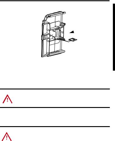
3.Insert the battery into the door, as shown.
4. Slide the battery door back until it clicks into position.
Install a 1784-CF64 or 1784-CF128 Industrial CompactFlash Card (optional)
ATTENTION |
Do not remove the CompactFlash card while the controller is reading from or |
||
|
|
|
writing to the card, as indicated by a flashing green CF status indicator. This |
|
|
|
could corrupt the data on the card or in the controller, as well as corrupt the |
|
|
|
latest firmware in the controller. |
|
|
|
|
The optional industrial CompactFlash card provides nonvolatile memory for a CompactLogix controller. The card is not required for controller operation.
Follow this procedure to install the card.
WARNING |
When you insert or remove the CompactFlash Card while power is on, an |
||
|
|
|
electrical arc can occur. This could cause an explosion in hazardous location |
|
|
|
installations. |
|
|
|
Be sure that power is removed or the area is nonhazardous before proceeding. |
|
|
|
|
|
|
|
|
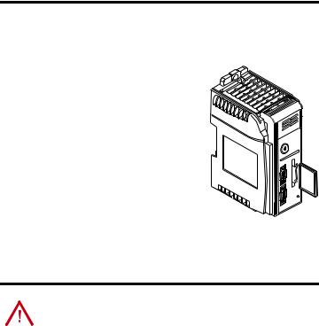
1. Push the locking tab to the right.
Publication 1769-IN069C-EN-P - May 2008
1769-L31 CompactLogix Controller 9
2.Insert the industrial CompactFlash card into the socket on the front of the controller, noting that the label of the CompactFlash card faces toward the left.
3. Match the orientation arrow on the card with the arrow on the front of the controller.
4. To remove the CompactFlash card, push the locking tab away from the CompactFlash card and pull the CompactFlash card from the socket.
Assemble the System
The controller can be attached to an adjacent I/O module or power supply before or after
mounting.
This procedure shows you how to install the controller in a CompactLogix system.
WARNING |
The CompactLogix controller is not designed for removal and insertion under |
||
|
|
|
power. |
|
|
|
If you insert or remove the module while backplane power is on, an electrical |
|
|
|
arc can occur. This could cause an explosion in hazardous location |
|
|
|
|
|
|
|
installations. |
|
|
|
Be sure that power is removed or the area is nonhazardous before proceeding. |
|
|
|
|
1. Disconnect line power.
Publication 1769-IN069C-EN-P - May 2008

101769-L31 CompactLogix Controller
2.Check that the lever of the adjacent module (A) is in the unlocked (fully right) position.


 C A
C A 


 D
D
B
F
E
B
3.Use the upper and lower tongue-and-groove slots (B) to secure the modules together.
4.Move the module back along the tongue-and-groove slots until the bus connectors line up with each other.
5.Use your fingers or a small screwdriver to push the module’s bus lever back slightly to clear the positioning tab (C).
6.Move the module’s bus lever fully to the left (D) until it clicks, being sure it is locked firmly in place.
|
|
|
When attaching the controller, power supply, and I/O modules, make sure the |
ATTENTION |
|||
|
|
|
bus connectors are securely locked together to be sure of proper electrical |
|
|
|
connection. |
|
|
|
|
|
|
|
|
7.Attach an end cap terminator (E) to the last module in the system by using the tongue-and-groove slots as before.
8.Lock the end cap bus terminator (F).
Publication 1769-IN069C-EN-P - May 2008
Loading...