


 Loading...
User Manual
Compact I/O RTD/Resistance Input Module
Catalog Number 1769-IR6

Important User Information
Solid-state equipment has operational characteristics differing from those of electromechanical equipment. Safety Guidelines for the Application, Installation and Maintenance of Solid State Controls (publication SGI-1.1 available from your local Rockwell Automation® sales office or online at http://www.rockwellautomation.com/literature/) describes some important differences between solid-state equipment and hard-wired electromechanical devices. Because of this difference, and also because of the wide variety of uses for solid-state equipment, all persons responsible for applying this equipment must satisfy themselves that each intended application of this equipment is acceptable.
In no event will Rockwell Automation, Inc. be responsible or liable for indirect or consequential damages resulting from the use or application of this equipment.
The examples and diagrams in this manual are included solely for illustrative purposes. Because of the many variables and requirements associated with any particular installation, Rockwell Automation, Inc. cannot assume responsibility or liability for actual use based on the examples and diagrams.
No patent liability is assumed by Rockwell Automation, Inc. with respect to use of information, circuits, equipment, or software described in this manual.
Reproduction of the contents of this manual, in whole or in part, without written permission of Rockwell Automation, Inc., is prohibited.
Throughout this manual, when necessary, we use notes to make you aware of safety considerations.
WARNING: Identifies information about practices or circumstances that can cause an explosion in a hazardous environment, which may lead to personal injury or death, property damage, or economic loss.
ATTENTION: Identifies information about practices or circumstances that can lead to personal injury or death, property damage, or economic loss. Attentions help you identify a hazard, avoid a hazard, and recognize the consequence.
SHOCK HAZARD: Labels may be on or inside the equipment, for example, a drive or motor, to alert people that dangerous voltage may be present.
BURN HAZARD: Labels may be on or inside the equipment, for example, a drive or motor, to alert people that surfaces may reach dangerous temperatures.
IMPORTANT Identifies information that is critical for successful application and understanding of the product.
Allen-Bradley, Rockwell Software, Rockwell Automation, Compact I/O, CompactLogix, MicroLogix, RSLogix 500, RSLOgix 5000, and TechConnect are trademarks of Rockwell Automation, Inc.
Trademarks not belonging to Rockwell Automation are property of their respective companies.

Summary of Changes
New and Updated
Information
This manual contains new and updated information. Changes throughout this revision are marked by change bars, as shown to the right of this paragraph.
This table contains the changes made to this revision.
Topic |
Page |
|
|
Updated RTD accuracy and temperature drift values |
14 |
|
|
Updated module accuracy values |
79 |
|
|
Rockwell Automation Publication 1769-UM005B-EN-P - March 2012 |
3 |

Summary of Changes
Notes:
4 |
Rockwell Automation Publication 1769-UM005B-EN-P - March 2012 |

|
|
Table of Contents |
Preface |
Who Should Use This Manual . . . . . . . . . . . . . . . . . . |
. . . . . . . . . . . . . . . . . . . . 9 |
|
How to Use This Manual . . . . . . . . . . . . . . . . . . . . . . . |
. . . . . . . . . . . . . . . . . . . . 9 |
|
Conventions Used in This Manual . . . . . . . . . . . . . . . |
. . . . . . . . . . . . . . . . . . . 9 |
|
Additional Resources . . . . . . . . . . . . . . . . . . . . . . . . . . . . |
. . . . . . . . . . . . . . . . . . . 9 |
|
Chapter 1 |
|
Overview |
General Description . . . . . . . . . . . . . . . . . . . . . . . . . . . . . |
. . . . . . . . . . . . . . . . . 11 |
|
RTD Compatibility . . . . . . . . . . . . . . . . . . . . . . . . . |
. . . . . . . . . . . . . . . . . 12 |
|
Resistance Device Compatibility. . . . . . . . . . . . . . |
. . . . . . . . . . . . . . . . . 15 |
|
Hardware Features . . . . . . . . . . . . . . . . . . . . . . . . . . . . . . |
. . . . . . . . . . . . . . . . . 16 |
|
General Diagnostic Features. . . . . . . . . . . . . . . . . . |
. . . . . . . . . . . . . . . . . 17 |
|
System Overview . . . . . . . . . . . . . . . . . . . . . . . . . . . . . . . . |
. . . . . . . . . . . . . . . . . 17 |
|
System Operation . . . . . . . . . . . . . . . . . . . . . . . . . . . |
. . . . . . . . . . . . . . . . . 17 |
|
Module Operation . . . . . . . . . . . . . . . . . . . . . . . . . . |
. . . . . . . . . . . . . . . . . 18 |
|
Module Field Calibration . . . . . . . . . . . . . . . . . . . . |
. . . . . . . . . . . . . . . . . 19 |
Quick Start for Experienced Users
Installation and Wiring
Chapter 2
Before You Begin. . . . . . . . . . . . . . . . . . . . . . . . . . . . . . . . . . . . . . . . . . . . . . . . . 21
Required Tools and Equipment . . . . . . . . . . . . . . . . . . . . . . . . . . . . . . . . . . . 21
What You Need To Do. . . . . . . . . . . . . . . . . . . . . . . . . . . . . . . . . . . . . . . . . . . 21
Chapter 3
Compliance to European Union Directives. . . . . . . . . . . . . . . . . . . . . . . . . 27 EMC Directive. . . . . . . . . . . . . . . . . . . . . . . . . . . . . . . . . . . . . . . . . . . . . . . 27
Low Voltage Directive . . . . . . . . . . . . . . . . . . . . . . . . . . . . . . . . . . . . . . . . 28
Power Requirements . . . . . . . . . . . . . . . . . . . . . . . . . . . . . . . . . . . . . . . . . . . . . 28 General Considerations. . . . . . . . . . . . . . . . . . . . . . . . . . . . . . . . . . . . . . . . . . . 28
Hazardous Location Considerations . . . . . . . . . . . . . . . . . . . . . . . . . . . 29
Prevent Electrostatic Discharge . . . . . . . . . . . . . . . . . . . . . . . . . . . . . . . . 29 Remove Power . . . . . . . . . . . . . . . . . . . . . . . . . . . . . . . . . . . . . . . . . . . . . . . 30
Selecting a Location . . . . . . . . . . . . . . . . . . . . . . . . . . . . . . . . . . . . . . . . . . 30
System Assembly . . . . . . . . . . . . . . . . . . . . . . . . . . . . . . . . . . . . . . . . . . . . . . . . . 32
Mounting . . . . . . . . . . . . . . . . . . . . . . . . . . . . . . . . . . . . . . . . . . . . . . . . . . . . . . . 33
Minimum Spacing. . . . . . . . . . . . . . . . . . . . . . . . . . . . . . . . . . . . . . . . . . . . 33 Panel Mounting . . . . . . . . . . . . . . . . . . . . . . . . . . . . . . . . . . . . . . . . . . . . . . 34
DIN Rail Mounting . . . . . . . . . . . . . . . . . . . . . . . . . . . . . . . . . . . . . . . . . . 35
Replacing a Single Module within a System . . . . . . . . . . . . . . . . . . . . . . . . . 35 Field Wiring Connections . . . . . . . . . . . . . . . . . . . . . . . . . . . . . . . . . . . . . . . . 36
System Wiring Guidelines. . . . . . . . . . . . . . . . . . . . . . . . . . . . . . . . . . . . . 36
RTD Wiring Considerations . . . . . . . . . . . . . . . . . . . . . . . . . . . . . . . . . . 37
Terminal Door Label . . . . . . . . . . . . . . . . . . . . . . . . . . . . . . . . . . . . . . . . . 37
Removing and Replacing the Terminal Block . . . . . . . . . . . . . . . . . . . 38 Wiring the Finger-Safe Terminal Block. . . . . . . . . . . . . . . . . . . . . . . . . 39
Wiring the Modules . . . . . . . . . . . . . . . . . . . . . . . . . . . . . . . . . . . . . . . . . . 39
Rockwell Automation Publication 1769-UM005B-EN-P - March 2012 |
5 |

Table of Contents
Module Data, Status, and
Channel Configuration
Wiring RTDs . . . . . . . . . . . . . . . . . . . . . . . . . . . . . . . . . . . . . . . . . . . . . . . . 41
Wiring Resistance Devices (Potentiometers) . . . . . . . . . . . . . . . . . . . . 42
Chapter 4
Module Memory Map . . . . . . . . . . . . . . . . . . . . . . . . . . . . . . . . . . . . . . . . . . . . 45
Input Image . . . . . . . . . . . . . . . . . . . . . . . . . . . . . . . . . . . . . . . . . . . . . . . . . . 46
Configuration File . . . . . . . . . . . . . . . . . . . . . . . . . . . . . . . . . . . . . . . . . . . . 46 Accessing Input Image File Data . . . . . . . . . . . . . . . . . . . . . . . . . . . . . . . . . . . 46
Input Data File . . . . . . . . . . . . . . . . . . . . . . . . . . . . . . . . . . . . . . . . . . . . . . . . . . . 47
Input Data Values . . . . . . . . . . . . . . . . . . . . . . . . . . . . . . . . . . . . . . . . . . . . 47 General Status Flag Bits (S0…S5). . . . . . . . . . . . . . . . . . . . . . . . . . . . . . . 48
Open-Circuit Flag Bits (OC0…OC5) . . . . . . . . . . . . . . . . . . . . . . . . . . 49
Over-Range Flag Bits (O0…O5). . . . . . . . . . . . . . . . . . . . . . . . . . . . . . . . 49 Under-Range Flag Bits (U0…U5) . . . . . . . . . . . . . . . . . . . . . . . . . . . . . . 49
Configuring Channels . . . . . . . . . . . . . . . . . . . . . . . . . . . . . . . . . . . . . . . . . . . . 50
Configuration Data File . . . . . . . . . . . . . . . . . . . . . . . . . . . . . . . . . . . . . . . 50
Channel Configuration . . . . . . . . . . . . . . . . . . . . . . . . . . . . . . . . . . . . . . . 51 Enabling or Disabling a Channel (Bit 15) . . . . . . . . . . . . . . . . . . . . . . . 53
Selecting Data Format (Bits 12…14). . . . . . . . . . . . . . . . . . . . . . . . . . . . 54
Selecting Input/Sensor Type (Bits 8…11) . . . . . . . . . . . . . . . . . . . . . . . 59 Selecting Temperature Units/Mode (Bit 7) . . . . . . . . . . . . . . . . . . . . . 59
Selecting Open-Circuit Response (Bits 5 and 6) . . . . . . . . . . . . . . . . . 59
Selecting Cyclic Lead Compensation (Bit 4) . . . . . . . . . . . . . . . . . . . . 60 Selecting Excitation Current (Bit 3) . . . . . . . . . . . . . . . . . . . . . . . . . . . . 60
Setting Filter Frequency (Bits 0…2). . . . . . . . . . . . . . . . . . . . . . . . . . . . . 61
Selecting Enable/Disable Cyclic
Autocalibration (Word 6, Bit 0) . . . . . . . . . . . . . . . . . . . . . . . . . . . . . . . 65
Determining Effective Resolution and Range . . . . . . . . . . . . . . . . . . . . . . . 65
Determining Module Update Time . . . . . . . . . . . . . . . . . . . . . . . . . . . . . . . . 72 Effects of Autocalibration on Module Update Time . . . . . . . . . . . . . 73
Calculating Module Update Time with
Autocalibration Enabled . . . . . . . . . . . . . . . . . . . . . . . . . . . . . . . . . . . . . . 74
Effects of Cyclic Lead Wire Compensation on Module
Update Time . . . . . . . . . . . . . . . . . . . . . . . . . . . . . . . . . . . . . . . . . . . . . . . . . 76 Calculating Module Update Time with Cyclic Lead Wire
Compensation Enabled . . . . . . . . . . . . . . . . . . . . . . . . . . . . . . . . . . . . . . . 77
Impact of Autocalibration and Lead Wire Compensation
on Module Startup. . . . . . . . . . . . . . . . . . . . . . . . . . . . . . . . . . . . . . . . . . . . 78
Effects of Autocalibration on Accuracy . . . . . . . . . . . . . . . . . . . . . . . . . . . . . 79
6 |
Rockwell Automation Publication 1769-UM005B-EN-P - March 2012 |

Table of Contents
Diagnostics and
Troubleshooting
Chapter 5
Safety Considerations . . . . . . . . . . . . . . . . . . . . . . . . . . . . . . . . . . . . . . . . . . . . 81
Indicator Lights . . . . . . . . . . . . . . . . . . . . . . . . . . . . . . . . . . . . . . . . . . . . . . 81
Activating Devices When Troubleshooting . . . . . . . . . . . . . . . . . . . . . 81 Stand Clear of the Equipment . . . . . . . . . . . . . . . . . . . . . . . . . . . . . . . . . 82
Program Alteration . . . . . . . . . . . . . . . . . . . . . . . . . . . . . . . . . . . . . . . . . . . 82
Safety Circuits . . . . . . . . . . . . . . . . . . . . . . . . . . . . . . . . . . . . . . . . . . . . . . . 82 Module Operation versus Channel Operation . . . . . . . . . . . . . . . . . . . . . . 82
Power-up Diagnostics . . . . . . . . . . . . . . . . . . . . . . . . . . . . . . . . . . . . . . . . . . . . 83
Channel Diagnostics . . . . . . . . . . . . . . . . . . . . . . . . . . . . . . . . . . . . . . . . . . . . . 83 Invalid Channel Configuration Detection . . . . . . . . . . . . . . . . . . . . . . 83
Out-of-Range Detection . . . . . . . . . . . . . . . . . . . . . . . . . . . . . . . . . . . . . . 83
Open-Wire or Short-Circuit Detection . . . . . . . . . . . . . . . . . . . . . . . . 84 Non-critical versus Critical Module Errors . . . . . . . . . . . . . . . . . . . . . . . . . 84
Module Error Definition Table. . . . . . . . . . . . . . . . . . . . . . . . . . . . . . . . . . . . 84
Module Error Field . . . . . . . . . . . . . . . . . . . . . . . . . . . . . . . . . . . . . . . . . . . 85
Extended Error Information Field . . . . . . . . . . . . . . . . . . . . . . . . . . . . . 86 Error Codes . . . . . . . . . . . . . . . . . . . . . . . . . . . . . . . . . . . . . . . . . . . . . . . . . . . . . 87
Module Inhibit Function . . . . . . . . . . . . . . . . . . . . . . . . . . . . . . . . . . . . . . . . . 88
Contacting Rockwell Automation . . . . . . . . . . . . . . . . . . . . . . . . . . . . . . . . . 89
Module Addressing and Programming with MicroLogix 1500 and RSLogix 500
Configuring the 1769-IR6 RTD Module with the Generic Profile
Configuring the 1769-IR6 Module in a Remote DeviceNet System with a 1769-ADN DeviceNet Adapter
Two’s Complement Binary Numbers
Appendix A
Module Addressing. . . . . . . . . . . . . . . . . . . . . . . . . . . . . . . . . . . . . . . . . . . . . . . 91
1769-IR6 Configuration File . . . . . . . . . . . . . . . . . . . . . . . . . . . . . . . . . . 92
Configuring the 1769-IR6 in a MicroLogix 1500 System . . . . . . . . . . . . 93
Appendix B
Configuring I/O Modules. . . . . . . . . . . . . . . . . . . . . . . . . . . . . . . . . . . . 100
Configuring a 1769-IR6 RTD Input Module . . . . . . . . . . . . . . . . . . 102
Appendix C
Configuring the 1769-IR6 . . . . . . . . . . . . . . . . . . . . . . . . . . . . . . . . . . . 106
Appendix D
Positive Decimal Values . . . . . . . . . . . . . . . . . . . . . . . . . . . . . . . . . . . . . . . . . 109
Negative Decimal Values. . . . . . . . . . . . . . . . . . . . . . . . . . . . . . . . . . . . . . . . . 110
Rockwell Automation Publication 1769-UM005B-EN-P - March 2012 |
7 |

Table of Contents
Notes:
8 |
Rockwell Automation Publication 1769-UM005B-EN-P - March 2012 |

Preface
Who Should Use This
Manual
How to Use This Manual
Conventions Used in This
Manual
Additional Resources
Read this preface to familiarize yourself with the rest of the manual.
Use this manual if you are responsible for designing, installing, programming, or troubleshooting control systems that use Allen-Bradley Compact™ I/O and/or compatible controllers, such as MicroLogix 1500 or CompactLogix.
As much as possible, we organized this manual to explain, in a task-by-task manner, how to install, configure, program, operate and troubleshoot a control system using the 1769-IR6.
The following conventions are used throughout this manual:
·Bulleted lists (like this one) provide information not procedural steps.
·Numbered lists provide sequential steps or hierarchical information.
·Italic type is used for emphasis.
·Text in this font indicates words or phrases you should type.
These documents contain additional information concerning related products from Rockwell Automation.
Resource |
Description |
|
|
1769 Compact I/O Modules Specifications Technical Data, |
Specifications of all 1769 Compact I/O modules |
publication 1769-TD006 |
|
|
|
Industrial Automation Wiring and Grounding Guidelines, publication |
Provides general guidelines for installing a Rockwell Automation |
1770-4.1 |
industrial system. |
|
|
Product Certifications website, http://www.ab.com |
Provides declarations of conformity, certificates, and other |
|
certification details. |
|
|
You can view or download publications at http:/www.rockwellautomation.com/literature/. To order paper copies of technical documentation, contact your local Allen-Bradley distributor or Rockwell Automation sales representative.
Rockwell Automation Publication 1769-UM005B-EN-P - March 2012 |
9 |

Preface
Notes:
10 |
Rockwell Automation Publication 1769-UM005B-EN-P - March 2012 |
Chapter 1
Overview
General Description
This chapter describes the six-channel 1769-IR6 RTD/resistance Input module and explains how the controller reads resistance temperature detector (RTD) or direct resistance-initiated analog input data from the module. Included is:
·a general description of hardware features
·an overview of module and system operation
·compatibility
The 1769-IR6 module supports RTD and direct resistance signal measurement applications that require up to six channels. The module digitally converts analog data and then stores the converted data in its image table.
The module supports connections from any combination of up to six input devices. Each channel is individually configurable via software for 2- or 3-wire RTD or direct resistance input devices. Channels are compatible with 4-wire sensors, but the fourth sense wire is not used. Two programmable excitation current values (0.5mA and 1.0mA) are provided, to limit RTD self-heating. When configured for RTD inputs, the module can convert the RTD readings into linearized digital temperature readings in °C or °F. When configured for resistance analog inputs, the module can convert voltages into linearized resistance values in ohms. The module assumes that the direct resistance input signal is linear prior to input to the module.
Each channel provides open-circuit (all wires), short-circuit (excitation and return wires only), and overand under-range detection and indication.
IMPORTANT The module accepts input from RTDs with up to 3 wires. If your application requires a 4-wire RTD, one of the two lead compensation wires is not used, and the RTD is treated like a 3-wire sensor. The third wire provides lead wire compensation. See Chapter 3, Installation and Wiring, for more information.
Rockwell Automation Publication 1769-UM005B-EN-P - March 2012 |
11 |

Chapter 1 |
Overview |
|
|
The following data formats are supported by the module.:
·raw/proportional
·engineering units x 1
·engineering units x 10
·scaled-for-PID
·percent full scale
Available filter frequencies are:
·10 Hz
·50 Hz
·60 Hz
·250 Hz
·500 Hz
·1 kHz
The module uses eight input words for data and status bits and seven configuration words. Module configuration is stored in the controller memory. Normally configuration is done via the controller’s programming software. In addition, some controllers support configuration via the user program. Refer to your controller manual for additional information. See Chapter 4, Module Data, Status, and Channel Configuration, for details on module configuration.
RTD Compatibility
An RTD consists of a temperature-sensing element connected by two, three, or four wires that provide input to the module. The following table lists the RTD types that you can use with the module, including their temperature range, effective resolution, and repeatability for both excitation currents, 0.5 and 1.0 mA.
12 |
Rockwell Automation Publication 1769-UM005B-EN-P - March 2012 |

Overview |
Chapter 1 |
|
|
Table 1 - RTD Specifications
RTD Type(1) |
|
Temperature Range Using |
Temperature Range Using |
Maximum |
Maximum |
|
|
|
0.5 mA Excitation |
1.0 mA Excitation |
Scaled |
Scaled |
|
|
|
|
|
Resolution |
Repeatability |
|
|
|
|
|
|
|
|
Copper 426 |
10 Ω |
Not allowed |
-100…260 °C (-148…500 °F) |
0.1 °C (0.1 °F) |
±0.2 °C (±0.4 °F) |
|
|
|
|
|
|
|
|
Nickel |
120 Ω |
-100…260 °C (-148…500 °F) |
-100…260 °C (-148…500 °F) |
0.1 °C (0.1 °F) |
±0.1 °C (±0.2 °F) |
|
618(2) |
|
|
|
|
|
|
Nickel 672 |
120 Ω |
-80…260 °C (-112…500 °F) |
-80…260 °C (-112…500 °F) |
0.1 °C (0.1 °F) |
±0.1 °C (±0.2 °F) |
|
|
|
|
|
|
|
|
Nickel-Iron |
604 Ω |
-200…180 °C (-328…338 °F) |
-100…200 °C (-148…392 °F) |
0.1 °C (0.1 °F) |
±0.1 °C (±0.2 °F) |
|
518 |
|
|
|
|
|
|
|
|
|
|
|
|
|
Platinum |
100 Ω |
-200…850 °C (-328…1562 °F) |
-200…850 °C (-328…1562 °F) |
0.1 °C (0.1 °F) |
±0.2 °C (±0.4 °F) |
|
385 |
|
|
|
|
|
|
200 Ω |
-200…850 °C (-328…1562 °F) |
-200…850 °C (-328…1562 °F) |
0.1 °C (0.1 °F) |
±0.2 °C (±0.4 °F) |
||
|
||||||
|
|
|
|
|
|
|
|
500 Ω |
-200…850 °C (-328…1562 °F) |
-200…850 °C (-328…1562 °F) |
0.1 °C (0.1 °F) |
±0.2 °C (±0.4 °F) |
|
|
|
|
|
|
|
|
|
1000 Ω |
-200…850 °C (-328…1562 °F) |
Not Allowed |
0.1 °C (0.1 °F) |
±0.2 °C (±0.4 °F) |
|
|
|
|
|
|
|
|
Platinum |
100 Ω |
-200C…630 °C (-328…1166 °F) |
-200…630 °C (-328…1166 °F) |
0.1 °C (0.1 °F) |
±0.2 °C (±0.4 °F) |
|
3916 |
|
|
|
|
|
|
200 Ω |
-200…630 °C (-328…1166 °F) |
-200…630 °C (-328…1166 °F) |
0.1 °C (0.1 °F) |
±0.2 °C (±0.4 °F) |
||
|
||||||
|
|
|
|
|
|
|
|
500 Ω |
-200…630 °C (-328…1166 °F) |
-200…630 °C (-328…1166 °F) |
0.1 °C (0.1 °F) |
±0.2 °C (±0.4 °F) |
|
|
|
|
|
|
|
|
|
1000 Ω |
-200…630 °C (-328…1166 °F) |
Not Allowed |
0.1 °C (0.1 °F) |
±0.2 °C (±0.4 °F) |
|
|
|
|
|
|
|
(1)Digits following the RTD type represent the temperature coefficient of resistance (α), which is defined as the resistance change per ohm per °C. For instance, platinum 385 refers to a platinum RTD with α = 0.00385 ohm/ohm - °C, or simply 0.00385/°C.
(2)Actual value at 0 °C is 100 Ω per DIN standard.
Rockwell Automation Publication 1769-UM005B-EN-P - March 2012 |
13 |

Chapter 1 Overview
The table below provide specifications for RTD accuracy and temperature drift. The ratings apply when a 50/60 Hz filter is used.
|
|
Table 2 - RTD Accuracy and Temperature Drift |
|
|
||
|
|
|
|
|
|
|
|
|
RTD Type |
|
Maximum Scaled Accuracy |
Maximum Scaled Accuracy |
Maximum Temperature Drift |
|
|
|
|
(25 °C with Calibration) |
(0…60 °C with Calibration) |
(from 25 °C without |
|
|
|
|
|
|
Calibration) |
|
|
|
|
|
|
|
|
|
Copper 426 |
10 Ω |
±0.8 °C (1.44 °F) |
±1.1 °C (1.98 °F) |
±0.032 °C/°C (0.032 °F/°F) |
|
|
|||||
|
|
|
|
|
|
|
|
|
Nickel 618 |
120 Ω |
±0.3 °C (±0.54 °F) |
±0.5 °C (±0.9 °F) |
±0.012 °C/°C (±0.012 °F/°F) |
|
|
|||||
|
|
|
|
|
|
|
|
|
Nickel 672 |
120 Ω |
±0.3 °C (±0.54 °F) |
±0.5 °C (±0.9 °F) |
±0.012 °C/°C (±0.012 °F/°F) |
|
|
|||||
|
|
|
|
|
|
|
|
|
Nickel-Iron 518 |
604 Ω |
±0.3 °C (±0.54 °F) |
±0.5 °C (±0.9 °F) |
±0.015 °C/°C (±0.015 °F/°F) |
|
|
|
|
|
|
|
|
|
Platinum 385 |
100 Ω |
±0.5 °C (±0.9 °F) |
±0.9 °C (±1.62 °F) |
±0.026 °C/°C (±0.026 °F/°F) |
|
|
|
|
|
|
|
|
|
|
200 Ω |
±0.5 °C (±0.9 °F) |
±0.9 °C (±1.62 °F) |
±0.026 °C/°C (±0.026 °F/°F) |
|
|
|
|
|
|
|
|
|
|
500 Ω |
±0.5 °C (±0.9 °F) |
±0.9 °C (±1.62 °F) |
±0.026 °C/°C (±0.026 °F/°F) |
|
|
|
|
|
|
|
|
|
|
1000 Ω |
±0.5 °C (±0.9 °F) |
±0.9 °C (±1.62 °F) |
±0.026 °C/°C (±0.026 °F/°F) |
|
|
|
|
|
|
|
|
|
Platinum 3916 |
100 Ω |
±0.4 °C (±0.72 °F) |
±0.8 °C (±1.44 °F) |
±0.023 °C/°C (±0.023 °F/°F) |
|
|
|
|
|
|
|
|
|
|
200 Ω |
±0.4 °C (±0.72 °F) |
±0.8 °C (±1.44 °F) |
±0.023 °C/°C (±0.023 °F/°F) |
|
|
|
|
|
|
|
|
|
|
500 Ω |
±0.4 °C (±0.72 °F) |
±0.8 °C (±1.44 °F) |
±0.023 °C/°C (±0.023 °F/°F) |
|
|
|
|
|
|
|
|
|
|
1000 Ω |
±0.4 °C (±0.72 °F) |
±0.8 °C (±1.44 °F) |
±0.023 °C/°C (±0.023 °F/°F) |
|
|
|
|
|
|
|
IMPORTANT |
When you are using any platinum (385) RTDs with 0.5 mA excitation current, the |
|
|
module’s accuracy is: |
|
|
· |
±0.5 °C (0.9 °F) after you apply power to the module or perform an |
|
|
autocalibration at 25 °C (77 °F) ambient, with module operating temperature at |
|
|
25 °C (77 °F). |
|
· |
±[0.5 °C (0.9 °F) + DT ± 0.026 deg./°C (±0.026 deg./°F)] after you apply power |
|
|
to the module or perform an autocalibration at 25 °C (77 °F) ambient, with |
|
|
module operating temperature between 0…60 °C (140 °F). DT is the temperature |
|
|
difference between the actual module operating temperature and 25°C (77 °F). |
|
|
The value 0.026 deg./°C (±0.026 deg./°F) is the temperature drift shown in the |
|
|
table above. |
|
· |
±0.9 °C after you apply power to the module or perform an autocalibration at |
|
|
60 °C (140 °F) ambient, with module operating temperature at 60 °C (140 °F). |
|
|
|
14 |
Rockwell Automation Publication 1769-UM005B-EN-P - March 2012 |

Overview Chapter 1
Resistance Device Compatibility
The following table lists the specifications for the resistance devices that you can use with the module.
Table 3 - Resistance Device Specifications
Resistance |
Resistance Range |
Resistance Range |
Accuracy(1) |
Temperature Drift |
Resolution |
Repeatability |
Device |
(0.5 mA Excitation) |
(1.0 mA Excitation) |
|
|
|
|
Type |
|
|
|
|
|
|
|
|
|
|
|
|
|
150 Ω |
0…150 Ω |
0…150 Ω |
±0.15 Ω |
±0.007 Ω/°C |
0.01 Ω |
±0.04 Ω |
|
|
|
|
(±0.013 Ω/°F) |
|
|
|
|
|
|
|
|
|
500 Ω |
0…500 Ω |
0…500 Ω |
±0.5 Ω |
±0.023 Ω/°C |
0.1 Ω |
±0.2 Ω |
|
|
|
|
(±0.041 Ω/°F) |
|
|
|
|
|
|
|
|
|
1000 Ω |
0…1000 Ω |
0…1000 Ω |
±1.0 Ω |
±0.043 Ω/°C |
0.1 Ω |
±0.2 Ω |
|
|
|
|
(±0.077 Ω/°F) |
|
|
|
|
|
|
|
|
|
3000 Ω |
0…3000 Ω |
Not allowed |
±1.5 Ω |
±0.072 Ω/°C |
0.1 Ω |
±0.2 Ω |
|
|
|
|
(±0.130 Ω/°F) |
|
|
|
|
|
|
|
|
|
(1) Accuracy values are based on the assumption that the module has been calibrated to the temperature range of 0…60 °C (32…140 °F).
Rockwell Automation Publication 1769-UM005B-EN-P - March 2012 |
15 |
Chapter 1 |
Overview |
|
|
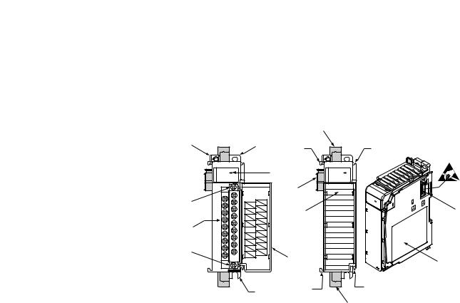
Hardware Features
The RTD/resistance module contains a removable terminal block (spare part number 1769-RTBN18) providing connections for six 3-wire inputs for any combination of RTD and resistance input devices. Channels are wired as differential inputs. The illustration below shows the hardware features of the module.
|
|
|
|
8a |
1 |
|
2a |
7a |
7a |
|
|
|
||
|
OK |
|
3 |
OK |
|
Analog |
|
|
Analog |
|
DANGER |
5a |
|
|
|
|
|
||
|
Do Not Remove RTB Under Power |
|
|
|
10a |
Unless Area is Non-Hazardous |
|
|
|
EXC 3 |
EXC 0 |
|
|
|
|
RTN 3- |
SENSE 0 |
9 |
5b |
|
RTN 0 |
|||
|
SENSE |
3 |
|
|
|
|
EXC 1 |
|
|
|
EXC 4 |
|
|
|
10 |
|
SENSE 1 |
|
|
SENSE |
RTN 1 |
|
|
|
|
4 |
|
|
|
|
RTN 4 |
|
|
|
|
|
EXC 2 |
|
|
|
EXC 5 |
|
|
|
10b |
|
SENSE 2 |
|
|
SENSE 5 |
|
|
||
RTN 5 |
RTN 2 |
|
|
|
|
|
Ensure Adjacent |
4 |
|
|
Bus Lever is Unlatched/Latched |
6 |
||
|
Before/After |
|||
|
Removing/Inserting Module |
|
|
|
|
|
1769-IR6 |
|
|
|
|
2b |
7b |
7b |
|
|
|
|
|
8b
Item |
Description |
|
|
1 |
bus lever (with locking function) |
|
|
2a |
upper panel mounting tab |
|
|
2b |
lower panel mounting tab |
|
|
3 |
module status indicator |
|
|
4 |
module door with terminal identification label |
|
|
5a |
movable bus connector with female pins |
|
|
5b |
stationary bus connector with male pins |
|
|
6 |
nameplate label |
|
|
7a |
upper tongue-and-groove slots |
|
|
7b |
lower tongue-and-groove slots |
|
|
8a |
upper DIN rail latch |
|
|
8b |
lower DIN rail latch |
|
|
9 |
write-on label (user ID tag) |
|
|
10 |
removable terminal block with finger-safe cover |
|
|
10a |
terminal block upper retaining screw |
|
|
10b |
terminal block lower retaining screw |
|
|
16 |
Rockwell Automation Publication 1769-UM005B-EN-P - March 2012 |

Overview |
Chapter 1 |
|
|
General Diagnostic Features
System Overview
A single diagnostic indicator helps you identify the source of problems that may occur during powerup or during normal channel operation. The indicator shows both status and power. See Chapter 5, Diagnostics and Troubleshooting, for details on power-up and channel diagnostics.
The modules communicate to the local controller or communication adapter through the 1769 bus interface. The modules also receive 5 and 24V DC power through the bus interface.
System Operation
At powerup, the module performs a check of its internal circuits, memory, and basic functions. During this time, the module status indicator remains off. If no faults are found during power-up diagnostics, the module status indicator is turned on.
After power-up checks are complete, the module waits for valid channel configuration data. If an invalid configuration is detected, the module generates a configuration error. Once a channel is properly configured and enabled, the module continuously converts the RTD or resistance input to a value within the range selected for that channel.
Each time the module reads an input channel, it tests the data for a fault (overor under-range, short-circuit, or open-circuit condition). If it detects a fault, the module sets a unique bit in the channel status word. See Input Data File on page 47.
Using the module image table, the controller reads the two’s compliment binary converted input data from the module. This typically occurs at the end of the program scan or when commanded by the control program. If the controller and the module determine that the data transfer has been made without error, the data is used in the control program.
Rockwell Automation Publication 1769-UM005B-EN-P - March 2012 |
17 |

Chapter 1 |
Overview |
|
|
Module Operation
As shown in the block diagram below, each input channel of the module consists of an RTD/resistance connection that accepts excitation current; a sense connection that detects lead wire resistance; and a return connection. The signals are multiplexed to an A/D converter that reads the RTD or resistance value and the lead wire resistance.
|
Input |
|
|
|
|
VA2 |
|
|
|
VA1 |
VA1 |
|
|
|
|
VA1 |
|
|
|
|
|
|
||||||||||||||||||||||||
|
|
|
|
|
|
|
|
|
|
|
|
|
|
|
|
|
EXC |
|
|
|
|
|
|
|
|
|
|
|
|
|
|
|
|
|
|
|
|
|
|
|
|
|
|
|
||
|
|
|
|
|
|
|
|
|
|
|
|
|
|
|
|
|
|
|
|
|
|
|
|
|
|
|
|
|
|
|
|
|
|
|
|
|
|
|
|
|
|
|
|
|
||
|
EXC0 |
CHN0 |
|
|
|
|
|
|
|
|
|
|
|
|
Current |
|
|
|
|
|
|
TXD |
|
|
|
|
|
|
|
|
|
|
|
|
|
|
|
|
||||||||
|
|
|
|
|
|
|
|
|
|
|
|
|
|
|
|
|
|
|
|
|
|
|
|
|
|
|
|
|
|
|
|
|
|
|
||||||||||||
|
|
|
|
|
|
|
|
|
|
|
|
|
|
|
AIN+1 |
|
|
|
|
|
|
|
|
|
|
|
|
|
|
|
|
|
|
|
|
|
|
|||||||||
|
|
|
|
|
|
|
|
|
|
|
|
|
|
|
|
|
|
|
|
|
|
|
|
|
|
|
|
|
|
|
|
|
|
|
|
|
||||||||||
|
|
|
|
|
|
|
|
|
|
|
|
|
|
|
|
|
|
|
|
|
|
|
|
|
|
|
|
|
|
|
|
|
|
|
|
|
|
|
|
|
|
|
|
|
||
|
|
|
|
|
|
|
|
|
|
|
|
|
|
|
|
|
|
|
|
|
|
|
|
|
|
|
|
|
|
|
|
|
|
|
|
|
|
|
|
|
|
|
|
|
|
|
|
|
|
|
|
|
|
|
|
|
|
|
|
|
|
|
|
|
|
|
|
|
|
|
|
|
|
|
|
|
|
|
|
|
|
|
|
|
|
|
|
|
|
|
|
|
|
|
SENSE0 |
|
|
|
|
Multiplexer |
|
|
|
|
|
|
|
A/D |
|
|
|
|
MCU |
|
|
|
|
|
|
|
|
|
|
|
|
|
|
|
ASIC |
|
||||||||||
|
|
|
|
|
|
|
|
|
|
|
|
|
|
|
|
|
|
|
|
|
|
|
|
|
|
|
|
|
|
|
||||||||||||||||
|
|
|
|
|
|
|
|
|
|
|
|
|
|
|
|
|
|
|
AIN+2 |
|
|
|
|
|
|
|
|
|
|
|
|
|
|
|
|
|
|
|
|
|
|
|
|
|
|
|
|
|
|
|
|
|
|
|
|
|
|
|
|
|
|
|
|
|
|
|
|
|
|
|
|
|
|
|
|
|
|
|
|
|
|
|
|
|
|
|
|
|
|
|
|
||
|
RTN0 |
|
|
|
|
|
|
|
|
|
|
|
|
|
|
|
|
|
|
|
|
|
|
|
|
|
|
|
|
|
|
|
|
|
|
|
|
|
|
|
|
|
|
|
|
|
|
|
|
|
|
|
|
|
|
|
|
|
|
|
|
|
|
|
|
AIN- |
|
|
|
|
|
|
|
|
|
|
|
|
|
|
|
|
|
|
|
|
|
|
|
|
|
|
|
|
|
|
|
|
|
|
|
|
|
|
|
|
|
|
|
|
|
|
|
|
|
|
|
|
|
|
|
|
|
|
|
|
|
|
|
|
|
|
|
|
|
|
|
|
||
|
|
|
|
|
|
|
|
|
|
|
|
|
|
|
|
|
|
|
|
|
|
|
|
|
|
|
|
|
|
|
|
|
|
|
|
|
|
|
|
|
|
|
|
|
||
|
|
|
|
|
|
|
|
|
|
|
|
|
|
|
|
|
|
|
|
|
|
|
|
|
|
|
|
|
|
|
|
|
|
|
|
|
|
|
|
|
|
|
|
|||
|
|
|
|
|
|
|
|
|
|
|
|
|
|
|
|
A-GND |
|
|
|
|
|
|
|
|
|
|
|
|
|
|
|
|
|
|
|
|
|
|
|
|
|
|
||||
|
|
|
|
|
|
|
|
|
|
|
|
|
|
|
|
|
|
|
|
|
|
|
|
|
|
|
|
|
|
|
|
|
|
|
|
|
|
|
|
|
|
|||||
|
|
|
|
|
|
|
|
|
|
|
|
|
|
|
|
|
|
|
|
|
|
|
|
|
|
|
|
|
|
|
|
|
|
|
|
|
|
|
|
|
|
|
||||
|
|
|
|
|
|
|
|
|
|
|
|
|
|
|
|
|
|
|
|
|
|
|
|
|
|
|
|
|
|
|
|
|
|
|
|
|
|
|
|
|
||||||
|
|
|
|
|
|
|
|
|
|
|
|
|
|
|
|
|
|
|
|
|
|
|
|
|
|
|
|
|
|
|
|
|
|
|
|
|
|
|
|
|
|
|
|
|
|
|
|
|
|
|
|
|
|
|
|
|
|
|
|
|
|
|
|
Vref |
|
VREF |
|
|
|
|
|
|
|
|
DC/DC |
|
VS1 |
||||||||||||||||
|
|
|
|
|
|
|
|
|
|
|
|
|
|
|
|
|
|
|||||||||||||||||||||||||||||
|
|
|
|
|
|
|
|
|
|
|
|
|
|
|
|
|
|
|
|
|
|
|
|
|
|
|
Power Supply |
|
|
|
|
|
|
|||||||||||||
|
|
|
|
|
|
VA3 |
|
|
|
|
|
|
|
|
|
|
|
|
|
|
|
|||||||||||||||||||||||||
|
|
|
|
|
|
|
|
|
|
|
|
|
|
|
|
|
|
|
|
|
|
|
|
|
|
|
||||||||||||||||||||
|
|
|
|
|
|
|
|
|
|
|
|
|
|
|
|
|
|
|
VA1 |
|
|
|
|
|
|
|
|
|
|
|
|
VS2 |
||||||||||||||
|
|
|
|
|
|
|
|
|
|
|
|
|
|
|
|
|
|
Channel Select |
|
|
|
|
|
|
|
|
|
|
||||||||||||||||||
|
|
|
|
|
|
|
|
|
|
|
|
|
|
|
|
|
|
|
|
|
|
VA2 |
|
|
|
|
|
|
|
|
|
|
|
|
|
|
|
|
|
|
|
|||||
|
|
|
|
|
|
|
|
|
|
|
|
|
|
|
|
|
|
|
|
|
|
|
|
|
|
|
|
|
|
|
|
|
|
|
|
|
|
|
|
|
|
|
|
|
|
|
|
|
|
|
|
|
|
|
|
|
|
|
|
|
|
|
|
|
|
|
|
|
|
|
|
|
|
|
|
|
|
|
|
|
|
|
|
|
|
|
|
|
|
|
|
|
|
|
|
|
|
|
|
|
|
|
|
|
|
|
|
|
|
|
|
|
|
|
|
|
|
|
VA3 |
|
|
|
|
|
|
|
|
|
|
|
|
|
|
|
|
|
|
|
|
|
|
|
|
1 |
|
|
|
|
|
|
|
|
|
|
|
|
|
|
|
|
|
|
|
|
|
|
|
|
|
|
|
|
|
|
|
|
|
|
|
|
|
|
S-GND |
||||
|
|
|
|
|
|
|
|
|
|
|
|
|
|
|
|
|
|
|
|
|
|
|
A-GND |
|
||||||||||||||||||||||
|
|
|
|
|
|
|
|
|
|
|
|
|
|
|
|
|
|
|
|
|
|
|
|
|
|
|||||||||||||||||||||
|
|
|
|
|
|
|
|
|
|
|
|
|
|
|
|
|
|
|
|
|
|
|
|
|
|
|
|
|
|
|
||||||||||||||||
|
|
|
2 |
|
|
|
|
|
|
|
|
|
|
|
|
|
|
|
|
|
|
|
|
|
|
|
|
|
|
|
||||||||||||||||
|
|
|
|
|
|
|
|
|
|
|
|
|
|
|
|
|
|
|
|
|
|
|
|
|
|
|
|
|
|
|
|
|
|
|
|
|
|
|
|
|
|
|
|
|
|
|
|
|
|
|
|
Channels 1…5 same as |
|
|
|
|
|
|
|
|
|
|
|
|
|
|
|
|
|
|
|
|
|
|
|
|
|
|
|
|
|
|
|
|
|
||||||||
|
|
|
|
|
|
|
|
|
|
|
|
|
|
|
|
|
|
|
|
|
|
|
|
|
|
|
|
|
|
|
|
|
|
|
|
|
|
|||||||||
|
|
|
3 |
|
|
|
|
|
|
|
|
|
|
|
|
|
|
|
|
|
|
|
|
|
|
|
|
|
|
|
|
|
|
|
|
|
||||||||||
|
|
|
channel 0 above. |
|
|
|
|
|
|
|
|
|
|
|
|
|
|
|
|
|
|
|
|
|
|
|
|
|
|
|
|
|
|
|
|
|
||||||||||
|
|
|
|
|
|
|
|
|
|
|
|
|
|
|
|
|
|
|
|
|
|
|
|
|
|
|
|
|
|
|
|
|
|
|
|
|
|
|
|
|
|
|
|
|
|
|
|
|
|
4 |
|
|
|
|
|
|
|
|
|
|
|
|
|
|
|
|
|
|
|
|
|
|
|
|
|
|
|
|
|
|
|
|
|
|
|
|
|
|
|
|
|
|
|
|
|
|
|
|
|
|
|
|
|
|
|
|
|
|
|
|
|
|
|
|
|
|
|
|
|
|
|
|
|
|
|
|
|
|
|
|
|
|
|
|
|
|
|
|
|
|
|
|
|
|
|
|
|
|
|
|
|
|
|
|
|
|
|
|
|
|
|
|
|
|
|
|
|
|
|
|
|
|
|
|
|
|
|
|
|
|
|
|
|
|
|
|
|
|
|
|
5 |
|
|
|
|
|
|
|
|
|
|
|
|
|
|
|
|
|
|
|
|
|
|
|
|
|
|
|
|
|
|
|
|
|
|
|
|
|
|
|
|
|
|
|
|
|
|
|
|
|
|
|
|
|
|
|
|
|
|
|
|
|
|
|
|
|
|
|
|
|
|
|
|
|
|
|
|
|
|
|
|
|
|
|
|
|
|
|
|
|
|
BUS
From the readings taken by the converter, the module returns an accurate temperature or resistance to the controller user program through the microprocessor. The module uses two bidirectional serial ports for communication, each using an optocoupler for isolation. A third optocoupler is used to reset the microprocessor if the module detects a loss of communication.
18 |
Rockwell Automation Publication 1769-UM005B-EN-P - March 2012 |

Overview |
Chapter 1 |
|
|
Module Field Calibration
The input module performs autocalibration when a channel is initially enabled. Autocalibration compensates for offset and gain drift of the A/D converter caused by temperature change within the module. An internal, high-precision, low drift voltage and system ground reference is used for this purpose. In addition, you can program the module to perform a calibration cycle once every 5 minutes. See Selecting Enable/Disable Cyclic Autocalibration (Word 6, Bit 0) on page 65 for information on configuring the module to perform periodic calibration.
Rockwell Automation Publication 1769-UM005B-EN-P - March 2012 |
19 |

Chapter 1 |
Overview |
|
|
Notes:
20 |
Rockwell Automation Publication 1769-UM005B-EN-P - March 2012 |
Chapter 2
Before You Begin
Required Tools and
Equipment
What You Need To Do
Quick Start for Experienced Users
This chapter can help you to get started using the 1769-IR6 module. We base the procedures here on the assumption that you have an understanding of Allen-Bradley controllers. You should understand electronic process control and be able to interpret the ladder logic instructions required to generate the electronic signals that control your application.
Because it is a start-up guide for experienced users, this chapter does not contain detailed explanations about the procedures listed. It does, however, reference other chapters in this book where you can get more information about applying the procedures described in each step.
If you have any questions or are unfamiliar with the terms used or concepts presented in the procedural steps, always read the referenced chapters and other recommended documentation before trying to apply the information.
Have the following tools and equipment ready:
·medium blade or cross-head screwdriver
·RTD or direct resistance input device
·shielded, twisted-pair cable for wiring (Belden 9501 or equivalent)
·controller (for example, a MicroLogix 1500 or CompactLogix controller)
·programming device and software (for example, RSLogix 500™ or RSLogix 5000™)
This chapter covers:
1.Ensuring that your power supply is adequate
2.Attaching and locking the module
3.Wiring the module
4.Configuring the module
5.Going through the startup procedure
Rockwell Automation Publication 1769-UM005B-EN-P - March 2012 |
21 |

Chapter 2 Quick Start for Experienced Users
6. Monitoring module operation
Step 1: |
Ensure that your 1769 system power supply(1) has sufficient current output to |
Reference |
|
support your system configuration. |
|
|
|
Chapter 3 |
|
|
(Installation and Wiring) |
|
|
|
The modules maximum current draw is shown below.
5V DC |
|
24V DC |
|
|
|
|
|
100 mA |
|
45 mA |
|
|
|
|
|
TIP |
The module cannot be located more than 8 modules away |
||
|
from the 1769 system power supply. |
||
(1)The system power supply could be a 1769-PA2, -PB2, -PA4, -PB4, or the internal power supply of a MicroLogix 1500 packaged controller.
.
Step 2: |
Attach and lock the module. |
|
Reference |
||
|
|
|
|
|
Chapter 3 |
|
|
|
|
|
(Installation and Wiring) |
|
|
|
|
|
|
|
|
|
TIP |
The modules can be panel or DIN rail mounted. Modules |
|
|
|
|
|
can be assembled before or after mounting. |
|
|
|
|
|
|
|
|
|
|
|
ATTENTION: Remove power before removing or |
|
|
|
|
|
inserting this module. When you remove or insert a |
|
|
|
|
|
module with power applied, an electrical arc may occur. |
|
|
|
|
|
||
|
|
|
|
||
|
|
|
|
|
|
22 |
Rockwell Automation Publication 1769-UM005B-EN-P - March 2012 |
Quick Start for Experienced Users |
Chapter 2 |
|
|
3


 4
4
2 


 1
1
6
1 5
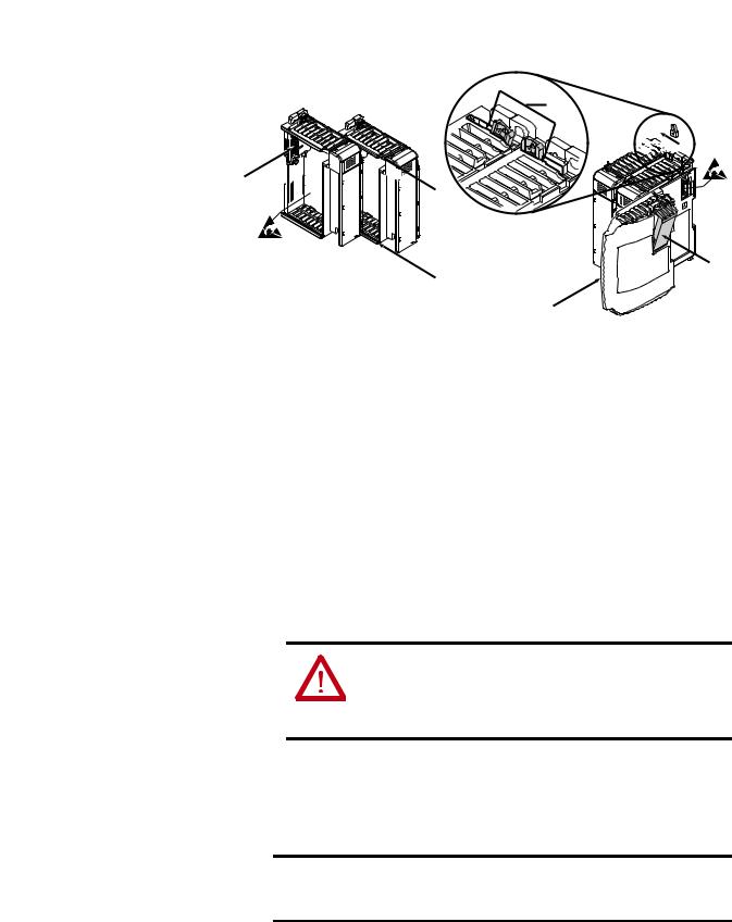
1.Check that the bus lever of the module to be installed is in the unlocked (fully right) position.
2.Use the upper and lower tongue-and-groove slots (1) to secure the modules together (or to a controller).
3.Move the module back along the tongue-and-groove slots until the bus connectors (2) line up with each other.
4.Push the bus lever back slightly to clear the positioning tab (3). Use your fingers or a small screwdriver.
5.To allow communication between the controller and module, move the bus lever fully to the left (4) until it clicks. Ensure it is locked firmly in place.
ATTENTION: When attaching I/O modules, it is very important that the bus connectors are securely locked together to ensure proper electrical connection.
6.Attach an end cap terminator (5) to the last module in the system by using the tongue-and-groove slots as before.
7.Lock the end cap bus terminator (6).
IMPORTANT A 1769-ECR or 1769-ECL right or left end cap respectively must be used to terminate the end of the bus.
Rockwell Automation Publication 1769-UM005B-EN-P - March 2012 |
23 |

Chapter 2 Quick Start for Experienced Users
Step 3: |
Wire the module. |
Reference |
Chapter 3
(Installation and Wiring)
Follow the guidelines below when wiring the module.
General
·This product is intended to be mounted to a well-grounded mounting surface such as a metal panel. Additional grounding connections from the module’s mounting tabs or DIN rail (if used) are not required unless the mounting surface cannot be grounded.
·Power and input wiring must be in accordance with Class I, Division 2 wiring methods (Article 501-4(b) of the National Electric Code NFPA70), and in accordance with the authority having jurisdiction.
·Channels are isolated from one another by ±10V DC maximum.
·Route field wiring away from any other wiring and as far as possible from sources of electrical noise, such as motors, transformers, contactors, and AC devices. In general, allow at least 15.2 cm (6 in.) of separation for every 120V of power.
·Routing field wiring in a grounded conduit can reduce electrical noise.
·If field wiring must cross AC or power cables, ensure that they cross at right angles.
·To ensure optimum accuracy, limit overall cable impedance by keeping your cable as short as possible. Locate the I/O system as close to your sensors or actuators as your application will permit.
·Use Belden shielded, twisted-pair wire to ensure proper operation and high immunity to electrical noise. See the table below for recommended types.
Configuration |
Recommended Cable |
|
|
2-wire |
Belden 9501 or equivalent |
|
|
3-wire |
Belden 9533 or equivalent |
less than 30.48 m (100 ft) |
|
|
|
3-wire |
Belden 83503 or equivalent |
greater than 30.48 m (100 ft) or high humidity conditions |
|
|
|
·Keep cable shield connection to ground as short as possible.
·Under normal conditions, the drain wire and shield junction should be connected to earth ground, via a panel or DIN rail mounting screw at the 1769-IR6 module end.
·If noise persists for a device, try grounding the opposite end of the cable. (You can only ground one end at a time.)
24 |
Rockwell Automation Publication 1769-UM005B-EN-P - March 2012 |

Quick Start for Experienced Users |
Chapter 2 |
|
|
·Refer to Industrial Automation Wiring and Grounding Guidelines, publication 1770-4.1, for additional information.
RTD Wiring Considerations
·The module requires three wires to compensate for lead resistance error.
·If using a 3-wire configuration for module connections, select cable to ensure that lead wire resistances match as closely as possible. Consider the following:
–To ensure temperature or resistance value accuracy, the resistance difference of the cable lead wires must be less than or equal to 0.01 Ω..
–Keep lead wire resistance as small as possible and less than 25 Ω .
–Use quality cable that has a small tolerance impedance rating and consistent impedance throughout its length.
–Use a heavy gauge lead wire with less resistance per foot.
Terminal Connections
1769-IR6
EXC 0
EXC 3
SENSE 0
SENSE 3
RTN 0
RTN 3
EXC 1
EXC 4
SENSE 1
SENSE 4
RTN 1
RTN 4
EXC 2
EXC 5
SENSE 2
SENSE 5
RTN 2
RTN 5
For examples of RTD and resistance device wiring see Wiring RTDs on page 41 and Wiring Resistance Devices (Potentiometers) on page 42.
Step 4: |
Configure the module. |
Reference |
Chapter 4
(Module Data, Status, and
Channel Configuration)
Rockwell Automation Publication 1769-UM005B-EN-P - March 2012 |
25 |

Chapter 2 Quick Start for Experienced Users
The configuration file is typically modified using the programming software configuration screen as shown below. It can also be modified through the control program, if supported by the controller. See the configuration file chart on Configuration Data File on page 50.
TIP |
The configuration default is to enable an analog channel. |
|
For improved system performance, disable any unused |
|
channels. |
Step 5: |
Go through the startup procedure. |
Reference |
Chapter 5
(Module Diagnostics and
Troubleshooting)
1.Apply power to the system.
2.Download your program, which contains the module configuration settings, to the controller.
3.Put the controller into Run mode. During a normal start-up, the module status indicator turns on.
TIP |
If the module status indicator does not turn on, cycle |
|
power. If the condition persists, contact your local |
|
distributor or Rockwell Automation for assistance. |
Step 6: |
Monitor the module status to check if the module is operating correctly |
Reference |
Chapter 5
(Module Diagnostics and
Troubleshooting)
Module and channel configuration errors are reported to the controller. These errors are typically reported in the controller’s I/O status file. Channel status data is also reported in the module’s input data table, so these bits can be used in your control program to flag a channel error.
26 |
Rockwell Automation Publication 1769-UM005B-EN-P - March 2012 |

Chapter 3
Installation and Wiring
Compliance to European Union Directives
This chapter tells you how to:
·determine the power requirements for the modules
·avoid electrostatic damage
·install the module
·wire the module’s terminal block
This product is approved for installation within the European Union and EEA regions. It has been designed and tested to meet the following directives.
EMC Directive
The 1769-IR6 module is tested to meet Council Directive 89/336/EEC Electromagnetic Compatibility (EMC) and the following standards, in whole or in part, documented in a technical construction file:
·EN 50081-2
EMC – Generic Emission Standard, Part 2 - Industrial Environment
·EN 50082-2
EMC – Generic Immunity Standard, Part 2 - Industrial Environment
This product is intended for use in an industrial environment.
Rockwell Automation Publication 1769-UM005B-EN-P - March 2012 |
27 |

Chapter 3 Installation and Wiring
Low Voltage Directive
Power Requirements
This product is tested to meet Council Directive 73/23/EEC Low Voltage, by applying the safety requirements of EN 61131-2 Programmable Controllers, Part 2 – Equipment Requirements and Tests.
The module receives +5V DC and 24V DC power from the system power supply through the CompactBus interface.
The maximum current drawn by the module is shown in the table below.
5V DC |
24V DC |
|
|
100 mA |
45 mA |
|
|
General Considerations
TIP |
When you configure your system, ensure that the total |
|
current draw of all the modules does not exceed the |
|
maximum current output of the system power supply. |
Compact I/O is suitable for use in an industrial environment when installed in accordance with these instructions. Specifically, this equipment is intended for
use in clean, dry environments (Pollution degree 2(1)) and to circuits not exceeding Over Voltage Category II(2) (IEC 60664-1).(3)
(1)Pollution Degree 2 is an environment where, normally, only non-conductive pollution occurs except that occasionally a temporary conductivity caused by condensation shall be expected.
(2)Over Voltage Category II is the load level section of the electrical distribution system. At this level transient voltages are controlled and do not exceed the impulse voltage capability of the product’s insulation.
(3)Pollution Degree 2 and Over Voltage Category II are International Electrotechnical Commission (IEC) designations.
28 |
Rockwell Automation Publication 1769-UM005B-EN-P - March 2012 |
Installation and Wiring |
Chapter 3 |
|
|
Hazardous Location Considerations
This equipment is suitable for use in Class I, Division 2, Groups A, B, C, D or non-hazardous locations only. The following WARNING statement applies to use in hazardous locations.
WARNING: EXPLOSION HAZARD
· Substitution of components may impair suitability for Class I, Division 2.
·Do not replace components or disconnect equipment unless power has been switched off or the area is known to be non-hazardous.
·Do not connect or disconnect components unless power has been switched off or the area is known to be non-hazardous.
·This product must be installed in an enclosure.
·All wiring must comply with N.E.C. article 501-4(b).
Prevent Electrostatic Discharge
ATTENTION: Electrostatic discharge can damage integrated circuits or semiconductors if you touch analog I/O module bus connector pins or the terminal block on the input module. Follow these guidelines when you handle the module:
·Touch a grounded object to discharge static potential.
·Wear an approved wrist-strap grounding device.
·Do not touch the bus connector or connector pins.
·Do not touch circuit components inside the module.
·If available, use a static-safe work station.
·When it is not in use, keep the module in its static-shield box.
Rockwell Automation Publication 1769-UM005B-EN-P - March 2012 |
29 |

Chapter 3 Installation and Wiring
Remove Power
WARNING: Remove power before removing or inserting this module. When you remove or insert a module with power applied, an electrical arc may occur. An electrical arc can cause personal injury or property damage by:
·sending an erroneous signal to your system’s field devices, causing unintended machine motion
·causing an explosion in a hazardous environment
·Electrical arcing causes excessive wear to contacts on both the module and its mating connector and may lead to premature failure.
Selecting a Location
Reducing Noise
Most applications require installation in an industrial enclosure to reduce the effects of electrical interference. RTD inputs are highly susceptible to electrical noise. Electrical noise coupled to the RTD inputs will reduce the performance (accuracy) of the module.
Group your modules to minimize adverse effects from radiated electrical noise and heat. Consider the following conditions when selecting a location for the module. Position the module:
·away from sources of electrical noise such as hard-contact switches, relays, and AC motor drives
·away from modules which generate significant radiated heat, such as the 1769-IA16. Refer to the module’s heat dissipation specification.
In addition, route shielded, twisted-pair wiring away from any high voltage I/O wiring.
30 |
Rockwell Automation Publication 1769-UM005B-EN-P - March 2012 |
Loading...