


 Loading...
Quick Start
Logix5000 Control Systems: Connect Kinetix 350 Drives over an EtherNet/IP Network
Catalog Numbers Logix5000 Controllers, Kinetix 350 Drives
Important User Information
Solid-state equipment has operational characteristics differing from those of electromechanical equipment. Safety Guidelines for the Application, Installation and Maintenance of Solid State Controls (publication SGI-1.1 available from your local Rockwell Automation sales office or online at http://www.rockwellautomation.com/literature/) describes some important differences between solid-state equipment and hard-wired electromechanical devices. Because of this difference, and also because of the wide variety of uses for solid-state equipment, all persons responsible for applying this equipment must satisfy themselves that each intended application of this equipment is acceptable.
In no event will Rockwell Automation, Inc. be responsible or liable for indirect or consequential damages resulting from the use or application of this equipment.
The examples and diagrams in this manual are included solely for illustrative purposes. Because of the many variables and requirements associated with any particular installation, Rockwell Automation, Inc. cannot assume responsibility or liability for actual use based on the examples and diagrams.
No patent liability is assumed by Rockwell Automation, Inc. with respect to use of information, circuits, equipment, or software described in this manual.
Reproduction of the contents of this manual, in whole or in part, without written permission of Rockwell Automation, Inc., is prohibited.
Throughout this manual, when necessary, we use notes to make you aware of safety considerations.
WARNING: Identifies information about practices or circumstances that can cause an explosion in a hazardous environment, which may lead to personal injury or death, property damage, or economic loss.
ATTENTION: Identifies information about practices or circumstances that can lead to personal injury or death, property damage, or economic loss. Attentions help you identify a hazard, avoid a hazard, and recognize the consequence.
SHOCK HAZARD: Labels may be on or inside the equipment, for example, a drive or motor, to alert people that dangerous voltage may be present.
BURN HAZARD: Labels may be on or inside the equipment, for example, a drive or motor, to alert people that surfaces may reach dangerous temperatures.
IMPORTANT Identifies information that is critical for successful application and understanding of the product.
Allen-Bradley, CompactLogix, Integrated Architecture, Kinetix, Logix5000, MP-Series, PanelView, POINT I/O, Rockwell Software, Rockwell Automation, RSLogix, Stratix 2000, and TechConnect are trademarks of Rockwell Automation, Inc.
Trademarks not belonging to Rockwell Automation are property of their respective companies.

Table of Contents
Preface
Prepare the Kinetix 350
Drive Hardware
Add a Kinetix 350 Drive to an RSLogix 5000 Project
Index
About This Publication. . . . . . . . . . . . . . . . . . . . . . . . . . . . . . . . . . . . . . . . . . . . 5
Before Using This Publication. . . . . . . . . . . . . . . . . . . . . . . . . . . . . . . . . . . . . . 5
Other Logix5000 Control System Quick Starts . . . . . . . . . . . . . . . . . . . . . . 8 Use Each Chapter . . . . . . . . . . . . . . . . . . . . . . . . . . . . . . . . . . . . . . . . . . . . . . . . . 8
Where to Start . . . . . . . . . . . . . . . . . . . . . . . . . . . . . . . . . . . . . . . . . . . . . . . . . . . . 9
How Hardware is Connected . . . . . . . . . . . . . . . . . . . . . . . . . . . . . . . . . . . . . 10 Required Software. . . . . . . . . . . . . . . . . . . . . . . . . . . . . . . . . . . . . . . . . . . . . . . . 10
Parts List . . . . . . . . . . . . . . . . . . . . . . . . . . . . . . . . . . . . . . . . . . . . . . . . . . . . . . . . 11
Additional Resources . . . . . . . . . . . . . . . . . . . . . . . . . . . . . . . . . . . . . . . . . . . . . 12
Chapter 1
Before You Begin. . . . . . . . . . . . . . . . . . . . . . . . . . . . . . . . . . . . . . . . . . . . . . . . . 13
What You Need. . . . . . . . . . . . . . . . . . . . . . . . . . . . . . . . . . . . . . . . . . . . . . . . . . 14
Follow These Steps . . . . . . . . . . . . . . . . . . . . . . . . . . . . . . . . . . . . . . . . . . . . . . . 15
Prepare the Panel. . . . . . . . . . . . . . . . . . . . . . . . . . . . . . . . . . . . . . . . . . . . . . . . . 16 Mount the Kinetix 350 Drive . . . . . . . . . . . . . . . . . . . . . . . . . . . . . . . . . . . . . 16 Ground the Kinetix 350 Drive . . . . . . . . . . . . . . . . . . . . . . . . . . . . . . . . . . . . 17 Disable the Safe Torque-off Feature. . . . . . . . . . . . . . . . . . . . . . . . . . . . . . . . 18 Wiring Diagram . . . . . . . . . . . . . . . . . . . . . . . . . . . . . . . . . . . . . . . . . . . . . . . . . 19 Wire the IOD Connector. . . . . . . . . . . . . . . . . . . . . . . . . . . . . . . . . . . . . . . . . 20 Wire the Back-up Power Connector . . . . . . . . . . . . . . . . . . . . . . . . . . . . . . . 22 Wire the Input Power Connector . . . . . . . . . . . . . . . . . . . . . . . . . . . . . . . . . 23 Wire the Motor Power Connector. . . . . . . . . . . . . . . . . . . . . . . . . . . . . . . . . 24 Apply the Motor Cable Shield Clamp. . . . . . . . . . . . . . . . . . . . . . . . . . . . . . 25 Wire the Motor Feedback Connector . . . . . . . . . . . . . . . . . . . . . . . . . . . . . 26 Connect the Kinetix 350 Drive to the EtherNet/IP Network . . . . . . . . 27 Assign an IP Address to the Kinetix 350 Drive . . . . . . . . . . . . . . . . . . . . . . 27 Additional Resources . . . . . . . . . . . . . . . . . . . . . . . . . . . . . . . . . . . . . . . . . . . . . 29
Chapter 2
Before You Begin. . . . . . . . . . . . . . . . . . . . . . . . . . . . . . . . . . . . . . . . . . . . . . . . . 31 What You Need. . . . . . . . . . . . . . . . . . . . . . . . . . . . . . . . . . . . . . . . . . . . . . . . . . 32
Follow These Steps . . . . . . . . . . . . . . . . . . . . . . . . . . . . . . . . . . . . . . . . . . . . . . . 33
Add the Kinetix 350 Drive to the RSLogix 5000 Project . . . . . . . . . . . . . 34 Configure the Motion Group . . . . . . . . . . . . . . . . . . . . . . . . . . . . . . . . . . . . . 37
Configure Axis Properties. . . . . . . . . . . . . . . . . . . . . . . . . . . . . . . . . . . . . . . . . 39
Apply Power to the Kinetix 350 Drive System . . . . . . . . . . . . . . . . . . . . . . 41 Test the Axis. . . . . . . . . . . . . . . . . . . . . . . . . . . . . . . . . . . . . . . . . . . . . . . . . . . . . 44
Tune an Axis. . . . . . . . . . . . . . . . . . . . . . . . . . . . . . . . . . . . . . . . . . . . . . . . . . . . . 46
Additional Resources . . . . . . . . . . . . . . . . . . . . . . . . . . . . . . . . . . . . . . . . . . . . . 46
. . . . . . . . . . . . . . . . . . . . . . . . . . . . . . . . . . . . . . . . . . . . . . . . . . . . . . . . . . . . . . . . . .47
Rockwell Automation Publication IASIMP-QS032A-EN-P - March 2012 |
3 |

Table of Contents
Notes:
4 |
Rockwell Automation Publication IASIMP-QS032A-EN-P - March 2012 |

Preface
About This Publication
This quick start provides examples and procedures for integrating a Kinetix 350 drive into any Logix5000 controllers control system over an EtherNet/IP network. The programming examples are not complex, and offer easy solutions to verify that devices are functioning and communicating properly.
IMPORTANT This publication describes basic example tasks you can complete when using a Kinetix 350 drive over an EtherNet/IP network. The tasks described are not the only tasks you can complete with the drive on an EtherNet/IP network. You will likely need to complete additional tasks when using a Kinetix 350 drive in a specific Logix5000 control system.
Before Using This Publication
You can only complete the tasks described in this publication after first completing some prequisite tasks with a Logix5000 controller. For example, before you can add a Kinetix 350 drive to an RSLogix 5000 project, as described on page 31, you must first create the project in a Logix5000 controller.
IMPORTANT The example graphics shown in Table 1 - Required Tasks to Complete before Using This Quick Start on page 6 are for
CompactLogix 5370 L3 controllers. Depending on the Logix5000 controller you are using, the specific steps to complete the tasks described in the table might vary.
For more information on how to complete these tasks with specific Logix5000 controllers, see
the Integrated Architecture : Logix5000 Control Systems Quick Starts Quick Reference, publication IASIMP-QR024.
Rockwell Automation Publication IASIMP-QS032A-EN-P - March 2012 |
5 |
Preface
Table 1 - Required Tasks to Complete before Using This Quick Start
Task |
Description |
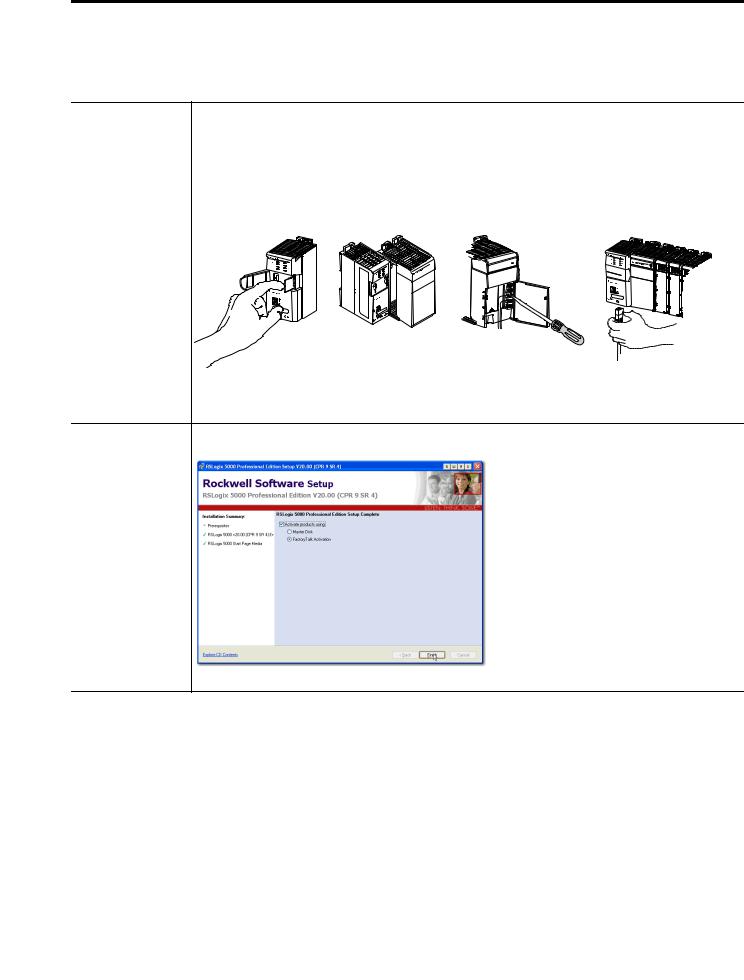
PreparetheLogix5000 |
Assemble the control system and connect to necessary communication networks. Some components, for |
control system |
example, the Logix5000 controller and system power supply, are required. Other components, for example, a |
hardware |
network communication module, are optional. |
|
These example graphics show the assembly of one Logix5000 controller. |
1 |
(Front) |
2 |
(Rear) |
IMPORTANT: This task does not include installation of specific hardware components, for example,
Kinetix 350 drives, used over the networks included in your application.
Prepare the computer Install necessary software on your complete. Some software, for example, RSLogix 5000 software.
6 |
Rockwell Automation Publication IASIMP-QS032A-EN-P - March 2012 |
|
Preface |
|
|
Table 1 - Required Tasks to Complete before Using This Quick Start |
|
|
|
Task |
Description |
|
|
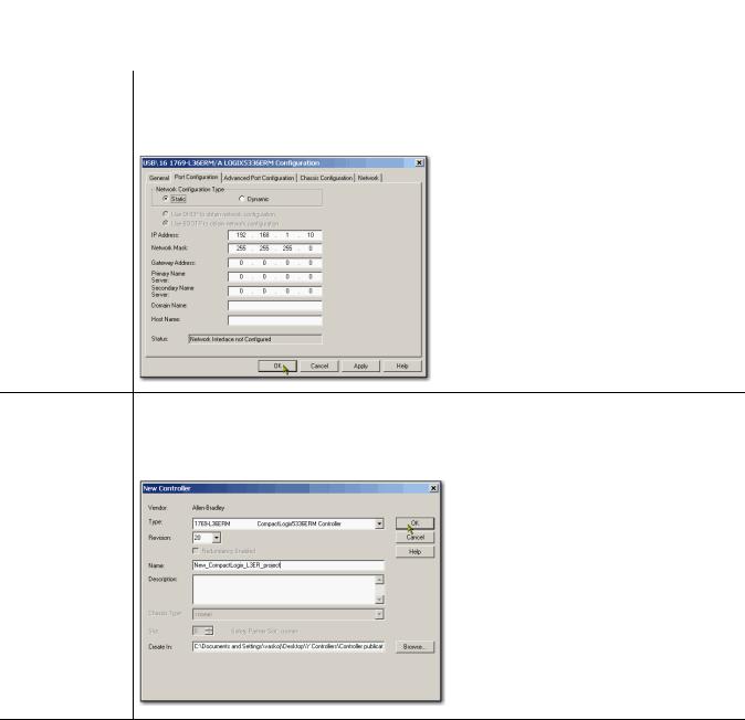
Configure the |
Complete required tasks associated with the networks used in your application, such as assigning an IP address |
networks |
to the controller’s communication port or communication module in your Logix5000 control system. |
Create an |
Create a project to be used with your Logix5000 controller. A project includes all desired control system |
RSLogix 5000 project |
components and necessary programming. For example, add ladder logic to test tasks associated with individual |
|
system components. |
Rockwell Automation Publication IASIMP-QS032A-EN-P - March 2012 |
7 |

Preface
Other Logix5000 Control System Quick Starts
This quick start describes how to use one device on one network in a Logix5000 control system. Typically, though, a Logix5000 control system includes more than the controller and one device on one network.
For example, if a Logix5000 control system operates on an EtherNet/IP network, in addition to a controller, power supply, and communication modules, the system might use remote I/O modules, drives, and HMI terminals.
Other quick starts describe how to use different devices on different networks in Logix5000 control systems. For more information, see the Integrated Architecture: Logix5000 Control Systems Quick Starts Quick Reference, publication IASIMP-QR024.
Use Each Chapter
The beginning of each chapter contains the following information. You should read these sections before beginning work in each chapter:
•Before You Begin - This section lists the tasks you must complete before starting the chapter.
•What You Need - This section lists the tools that are required to complete the tasks in the chapter.
•Follow These Steps - This section illustrates the steps in the current chapter.
8 |
Rockwell Automation Publication IASIMP-QS032A-EN-P - March 2012 |
Preface
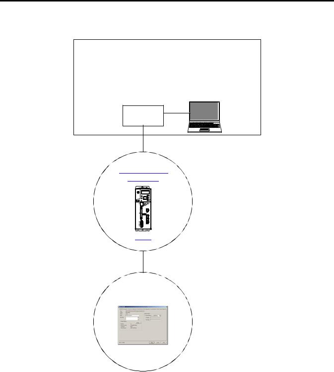
Where to Start
Prerequisite Tasks
Described in Before Using This Publication on page 5.
1.Prepare the Logix5000 control system hardware
2.Prepare the computer
3.Configure the networks
4.Create an RSLogix 5000 project
Logix5000
Controller
Add a Kinetix 350 Drive to an RSLogix 5000 Project
page 31
Rockwell Automation Publication IASIMP-QS032A-EN-P - March 2012 |
9 |
Preface
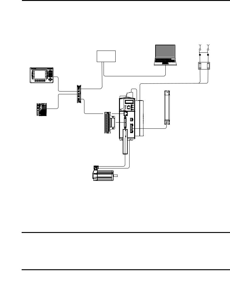
How Hardware is Connected
This graphic shows an example control system that uses a Kinetix 350 drive.
Single-phase Input Power
Logix5000 |
Computer with |
RSLogix 5000 Software |
|
Controller |
|
PanelView Plus Terminal |
|
Stratix 2000 Switch |
|
1734 POINT I/O
Modules
1 |
|
2 |
AC Line Filter |
3 |
|
5 |
Kinetix 350 |
4 |
|
|
Drive |
|
Shunt |
|
Resistor |
Terminal Expansion Block |
|
Motor Feedback Cable
MP-Series Rotary Motor
Required Software
To complete examples in this quick start, you need RSLogix 5000 software. RSLogix 5000 software is required to create or change RSLogix 5000 projects that use Kinetix 350 drives.
IMPORTANT This quick start uses RSLogix 5000 software, version 20.00.00 or later, because the example Logix5000 controller, and associated tasks, described herein are completed in a CompactLogix 5370 L3 control system. CompactLogix 5370 L3 control systems require RSLogix 5000 software, version 20.00.00 or later.
If you connect a Kinetix 350 drive over an EtherNet/IP network in a Logix5000 control system that uses a different Logix 5000 controller, the minimum version may differ.
10 |
Rockwell Automation Publication IASIMP-QS032A-EN-P - March 2012 |
Preface
Parts List
You need these parts to complete the tasks described in this quick start.
|
Quantity |
Cat. No. |
Description |
|
|
|
|
|
1 |
2097-V31PR2-LM |
Kinetix 350 Single Axis Ethernet/IP Servo Drive |
|
|
|
|
|
1 |
MPL-A310P-MJ72AA |
MP-Series Low-inertia Servo Motor |
|
|
|
|
|
1 |
The connectors required to |
6-pin Safe Torque Off (STO) Connector |
|
|
use Kinetix 350 drives vary |
|
|
1 |
6-pin Motor Power (MP) Connector |
|
|
|
by drive catalog number. |
|
|
1 |
The specific connectors to |
24V DC Back-up Power (BP) Connector |
|
|
|
|
|
1 |
4- pin General-purpose AC Input Power (IPD) Connector |
|
|
be used with your |
||
|
|
|
|
|
|
2097-V31PR2-LM drive |
|
|
|
ship with the drive. |
|
|
|
You do not need to order |
|
|
|
this part separately. |
|
|
|
|
|
|
1 |
2097-TB1 |
Bulletin 2097 I/O Terminal Expansion Block - 50-pin SCSI I/O (IOD) Connector |
|
|
|
|
|
1 |
2090-CPWM7DF-16AA03 |
6-pin Standard Power Cable with SpeedTec DIN Connector Type 923 |
|
|
|
|
|
1 |
2090-CFBM7DD-CEAA03 |
Standard Feedback Cable with SpeedTec DIN Connector Type 623 |
|
|
|
|
|
1 |
1585J-M8PBJM-2 |
RJ45 to RJ45 patchcord Ethernet cables |
|
|
|
|
|
3 |
|
Jumper wires |
|
|
|
|
For a list of parts required to complete the prerequisite tasks listed in Table 1 - Required Tasks to Complete before Using This Quick Start on page 6, see the documentation describing those tasks.
Rockwell Automation Publication IASIMP-QS032A-EN-P - March 2012 |
11 |

Preface
Additional Resources
Resource |
Description |
|
|
Kinetix 350 Single-axis EtherNet/IP Servo Drives User |
Describes how to install, wire, configure, operate, and troubleshoot your |
Manual, publication 2097-UM002 |
Kinetix 350 drive. |
|
|
Kinetix 350 Single-axis EtherNet/IP Servo Drives |
Describes how to install and wire your Kinetix 350 drive. |
Installation Instructions, publication 2097-IN008 |
|
|
|
EtherNet/IP Modules in Logix5000 Control Systems, |
Describes how to install, configure, and operate EtherNet/IP modules. |
publication ENET-UM001 |
|
|
|
Industrial Automation Wiring and Grounding Guidelines, |
Provides general guidelines for installing a Rockwell Automation industrial |
publication 1770-4.1 |
system. |
|
|
Product Certifications website, http://www.ab.com |
Provides declarations of conformity, certificates, and other certification |
|
details. |
|
|
You can view or download publications at http://www.rockwellautomation.com/literature/. To order paper copies of technical documentation, contact your local Allen-Bradley distributor or Rockwell Automation sales representative.
12 |
Rockwell Automation Publication IASIMP-QS032A-EN-P - March 2012 |

Chapter 1
Prepare the Kinetix 350 Drive Hardware
In this chapter, you learn how to complete the following tasks:
•Mount a 2097-V31PR2-LM drive.
•Make multiple connections, for example, power, feedback and resistor connections to the drive.
•Configure EtherNet/IP communication for the drive.
Before You Begin
You must complete these tasks described in Before Using This Publication on page 5 before using this chapter:
•Prepare the Logix5000 control system hardware
•Prepare the computer
•Configure the networks - The tasks described in this chapter require an EtherNet/IP network.
•Create an RSLogix 5000 project
The example RSLogix 5000 project used in this chapter uses a CompactLogix 5370 L3 controller.
Rockwell Automation Publication IASIMP-QS032A-EN-P - March 2012 |
13 |

Chapter 1 Prepare the Kinetix 350 Drive Hardware
What You Need
This table lists the products you need to complete the tasks described in this chapter.
|
Quantity |
Cat. No. |
Description |
|
|
|
|
|
1 |
2097-V31PR2-LM |
Kinetix 350 Single Axis Ethernet/IP Servo Drive |
|
|
|
|
|
1 |
MPL-A310P-MJ72AA |
MP-Series Low-inertia Servo Motor |
|
|
|
|
|
1 |
The connectors required to |
6-pin Safe Torque Off (STO) Connector |
|
|
use Kinetix 350 drives vary |
|
|
1 |
6-pin Motor Power (MP) Connector |
|
|
|
by drive catalog number. |
|
|
1 |
The specific connectors to |
24V DC Back-up Power (BP) Connector |
|
|
|
|
|
1 |
4- pin General-purpose AC Input Power (IPD) Connector |
|
|
be used with your |
||
|
|
|
|
|
|
2097-V31PR2-LM drive |
|
|
|
ship with the drive. |
|
|
|
You do not need to order |
|
|
|
this part separately. |
|
|
|
|
|
|
1 |
2097-TB1 |
Bulletin 2097 I/O Terminal Expansion Block - 50-pin SCSI I/O (IOD) Connector |
|
|
|
|
|
1 |
2090-CPWM7DF-16AA03 |
6-pin Standard Power Cable with SpeedTec DIN Connector Type 923 |
|
|
|
|
|
1 |
2090-CFBM7DD-CEAA03 |
Standard Feedback Cable with SpeedTec DIN Connector Type 623 |
|
|
|
|
|
1 |
1585J-M8PBJM-2 |
RJ45 to RJ45 patchcord Ethernet cables |
|
|
|
|
|
3 |
|
Jumper wires |
|
|
|
|
14 |
Rockwell Automation Publication IASIMP-QS032A-EN-P - March 2012 |
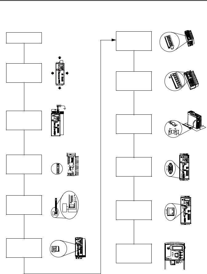
Follow These Steps
Prepare the Panel
page 16
Mount the
Kinetix 350 Drive
page 17
Ground the
Kinetix 350 Drive
page 17
Disable the Safe
Torque-off Feature
page 18
Wire the IOD
Connector
page 20
STO


 6 5 4 3 2 1
+
-
Pin46 |
Pin25 |
Pin47 |
Pin26 |
Pin48 |
Pin27 |
Pin49 |
Pin28 |
Pin50 |
Pin29 |
Wire the Back-up |
+ |
+24V DC |
|
Power Connector |
|||
- |
-24V DC |
||
|
24 |
|
|
page 22 |
|
|
Prepare the Kinetix 350 Drive Hardware |
Chapter 1 |
Wire the Input
Power Connector
page 23
Wire the Motor Power |
PE |
W |
|
Connector |
W |
V |
|
|
V |
|
U |
|
U |
page 24 |
|
Apply the Motor
Cable Shield Clamp
page 25
Wire the Motor
Feedback Connector
page 26
Connect the Kinetix 350
Drive to the EtherNet/IP
Network
page 27
Assign an IP Address to the Kinetix 350 Drive
page 27
Rockwell Automation Publication IASIMP-QS032A-EN-P - March 2012 |
15 |
Chapter 1 Prepare the Kinetix 350 Drive Hardware
Prepare the Panel
You must install the 2097-V31PR2-LM drive on a grounded panel. This quick start assumes you installed a panel when you fulfilled the prerequisite task of installing the Logix5000 control system hardware:
•If you have already installed a painted, grounded panel, move to section Mount the Kinetix 350 Drive.
•If you have not already installed a painted, grounded panel, do so before proceeding to the next section.
For more information on properly installing a panel that you can use with a Kinetix 350 drive, see the Kinetix 350 Single-axis EtherNet/IP Servo Drives User Manual, publication 2097-UM002.
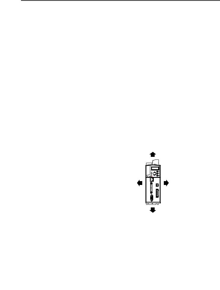
Mount the Kinetix 350 Drive
1.Verify that you have at least the minimum clearance to mount your 2097-V31PR2-LM drive on
the panel.
25.0 mm (1.0 in.)
3 mm (0.12 in.) |
3 mm (0.12 in.) |
25.0 mm (1.0 in.)
16 |
Rockwell Automation Publication IASIMP-QS032A-EN-P - March 2012 |
Loading...