


 Loading...
Logix5000 Controllers
Catalog Numbers 1756 ControlLogix, 1756 GuardLogix, 1768 CompactLogix, 1768 Compact GuardLogix,
1769 CompactLogix, 1789 SoftLogix, PowerFlex with DriveLogix
Quick Start

Important User Information
Solid state equipment has operational characteristics differing from those of electromechanical equipment. Safety Guidelines for the Application, Installation and Maintenance of Solid State Controls (publication SGI-1.1 available from your local Rockwell Automation sales office or online at http://www.rockwellautomation.com/literature/) describes some important differences between solid state equipment and hard-wired electromechanical devices. Because of this difference, and also because of the wide variety of uses for solid state equipment, all persons responsible for applying this equipment must satisfy themselves that each intended application of this equipment is acceptable.
In no event will Rockwell Automation, Inc. be responsible or liable for indirect or consequential damages resulting from the use or application of this equipment.
The examples and diagrams in this manual are included solely for illustrative purposes. Because of the many variables and requirements associated with any particular installation, Rockwell Automation, Inc. cannot assume responsibility or liability for actual use based on the examples and diagrams.
No patent liability is assumed by Rockwell Automation, Inc. with respect to use of information, circuits, equipment, or software described in this manual.
Reproduction of the contents of this manual, in whole or in part, without written permission of Rockwell Automation, Inc., is prohibited.
Throughout this manual, when necessary, we use notes to make you aware of safety considerations.
WARNING
Identifies information about practices or circumstances that can cause an explosion in a hazardous environment, which may lead to personal injury or death, property damage, or economic loss.
IMPORTANT Identifies information that is critical for successful application and understanding of the product.
ATTENTION
Identifies information about practices or circumstances that can lead to personal injury or death, property damage, or economic loss. Attentions help you identify a hazard, avoid a hazard, and recognize the consequence
SHOCK HAZARD
Labels may be on or inside the equipment, for example, a drive or motor, to alert people that dangerous voltage may be present.
BURN HAZARD
Labels may be on or inside the equipment, for example, a drive or motor, to alert people that surfaces may reach dangerous temperatures.
Allen-Bradley, Rockwell Automation, CompactLogix, ControlLogix, DriveLogix, FactoryTalk Batch, FactoryTalk View SE, PhaseManager, PowerFlex, RSLinx, RSLinx Classic, RSLogix 5000, SoftLogix, and TechConnect are trademarks of Rockwell Automation, Inc.
Trademarks not belonging to Rockwell Automation are property of their respective companies.

Summary of Changes
This version of the quick start corresponds to revision 18 of the Logix5000 controller firmware.
Change |
Page |
|
|
|
|
||
|
|
|
|
Descriptions of controller modes |
32 |
|
|
|
|
||
|
|
|
|
Language switching |
108 |
|
|
|
|
||
|
|
|
|
Additional information for finalizing edits in larger projects |
124 |
|
|
|
|
||
|
|
|
|
Publication 1756-QS001E-EN-P - October 2009 |
3 |

Summary of Changes
Notes:
4 |
Publication 1756-QS001E-EN-P - October 2009 |

|
Table of Contents |
|
Preface |
About This Publication . . . . . . . . . . . . . . . . . . . . . . . . . . . . . . . . . . . . . |
. 9 |
|
Required Software . . . . . . . . . . . . . . . . . . . . . . . . . . . . . . . . . . . . . . . . . |
. 9 |
|
Additional Resources . . . . . . . . . . . . . . . . . . . . . . . . . . . . . . . . . . . . . . . |
10 |
|
Chapter 1 |
|
Program and Test a Simple Project |
What You Need . . . . . . . . . . . . . . . . . . . . . . . . . . . . . . . . . . . . . . . . . . . |
11 |
|
Before You Begin. . . . . . . . . . . . . . . . . . . . . . . . . . . . . . . . . . . . . . . . . . |
12 |
|
Follow These Steps . . . . . . . . . . . . . . . . . . . . . . . . . . . . . . . . . . . . . . . . |
13 |
|
Create a Project for the Controller . . . . . . . . . . . . . . . . . . . . . . . . . . . . |
14 |
|
Conventions for Names . . . . . . . . . . . . . . . . . . . . . . . . . . . . . . . . . |
15 |
|
Add Your I/O Modules. . . . . . . . . . . . . . . . . . . . . . . . . . . . . . . . . . . . . |
15 |
|
Look at Your I/O Data . . . . . . . . . . . . . . . . . . . . . . . . . . . . . . . . . . . . . |
17 |
|
Ladder Logic. . . . . . . . . . . . . . . . . . . . . . . . . . . . . . . . . . . . . . . . . . . . . . |
19 |
|
Enter Ladder Logic . . . . . . . . . . . . . . . . . . . . . . . . . . . . . . . . . . . . . |
20 |
|
Enter a Function Block Diagram . . . . . . . . . . . . . . . . . . . . . . . . . . . . . |
21 |
|
Create a Routine. . . . . . . . . . . . . . . . . . . . . . . . . . . . . . . . . . . . . . . . |
21 |
|
Call the Routine . . . . . . . . . . . . . . . . . . . . . . . . . . . . . . . . . . . . . . . . |
22 |
|
Enter a Function Block Diagram . . . . . . . . . . . . . . . . . . . . . . . . . . |
23 |
|
Configure a Function Block Instruction. . . . . . . . . . . . . . . . . . . . . |
24 |
|
Assign Alias Tags for Your Devices . . . . . . . . . . . . . . . . . . . . . . . . . . . |
25 |
|
Show or Hide Alias Information. . . . . . . . . . . . . . . . . . . . . . . . . . . |
27 |
|
Establish a Serial Connection to the Controller . . . . . . . . . . . . . . . . . . |
28 |
|
Download a Project to the Controller. . . . . . . . . . . . . . . . . . . . . . . . . . |
30 |
|
Select the Operating Mode of the Controller . . . . . . . . . . . . . . . . . . . . |
32 |
|
Chapter 2 |
|
Organize a Project |
What You Need . . . . . . . . . . . . . . . . . . . . . . . . . . . . . . . . . . . . . . . . . . . |
35 |
|
Before You Begin. . . . . . . . . . . . . . . . . . . . . . . . . . . . . . . . . . . . . . . . . . |
35 |
|
Follow These Steps . . . . . . . . . . . . . . . . . . . . . . . . . . . . . . . . . . . . . . . . |
36 |
|
Configure the Task Execution. . . . . . . . . . . . . . . . . . . . . . . . . . . . . . . . |
36 |
|
Create Additional Programs. . . . . . . . . . . . . . . . . . . . . . . . . . . . . . . . . . |
38 |
|
Create User-defined Data Types . . . . . . . . . . . . . . . . . . . . . . . . . . . . . . |
40 |
|
Define Your Routines . . . . . . . . . . . . . . . . . . . . . . . . . . . . . . . . . . . |
43 |
|
Define a Routine for Each Section of a Machine or Process . . . . |
44 |
|
Identify the Programming Languages That Are Installed . . . . . . . |
44 |
|
Assign a Programming Language to Each Routine . . . . . . . . . . . . |
45 |
|
Divide Each Routine Into More Meaningful Increments . . . . . . . |
46 |
|
Assign Main Routines . . . . . . . . . . . . . . . . . . . . . . . . . . . . . . . . . . . . . . |
47 |
|
Configure the Controller . . . . . . . . . . . . . . . . . . . . . . . . . . . . . . . . . . . . |
48 |
|
Configure I/O Modules. . . . . . . . . . . . . . . . . . . . . . . . . . . . . . . . . . . . . |
49 |
Publication 1756-QS001E-EN-P - October 2009 |
5 |

Table of Contents |
|
|
|
Chapter 3 |
|
Program Add-On Instructions |
What You Need . . . . . . . . . . . . . . . . . . . . . . . . . . . . . . . . . . . . . . . . . . . |
51 |
|
Follow These Steps . . . . . . . . . . . . . . . . . . . . . . . . . . . . . . . . . . . . . . . . |
51 |
|
Insert an Add-On Instruction . . . . . . . . . . . . . . . . . . . . . . . . . . . . . . . . |
52 |
|
Copy an Add-On Instruction Definition . . . . . . . . . . . . . . . . . . . . . . . |
53 |
|
Import an Add-On Instruction Definition . . . . . . . . . . . . . . . . . . . . . . |
54 |
|
Access a Parameter That Is Not Visible . . . . . . . . . . . . . . . . . . . . . . . . |
55 |
|
Function Block. . . . . . . . . . . . . . . . . . . . . . . . . . . . . . . . . . . . . . . . . |
55 |
|
Ladder Logic and Structured Text . . . . . . . . . . . . . . . . . . . . . . . . . |
55 |
|
Monitor or Change the Value of a Parameter of an |
|
|
Add-On Instruction . . . . . . . . . . . . . . . . . . . . . . . . . . . . . . . . . . . . . . . . |
56 |
|
View the Logic of an Add-On Instruction . . . . . . . . . . . . . . . . . . . . . . |
57 |
|
Edit and Monitor an Add-On Instruction . . . . . . . . . . . . . . . . . . . . . . |
58 |
|
Update an Add-On Instruction to a Newer Revision . . . . . . . . . . . . . |
58 |
|
Chapter 4 |
|
Program an Equipment Phase |
What You Need . . . . . . . . . . . . . . . . . . . . . . . . . . . . . . . . . . . . . . . . . . . |
59 |
|
Follow These Steps . . . . . . . . . . . . . . . . . . . . . . . . . . . . . . . . . . . . . . . . |
59 |
|
Create an Equipment Phase. . . . . . . . . . . . . . . . . . . . . . . . . . . . . . . . . . |
60 |
|
Create a State Routine . . . . . . . . . . . . . . . . . . . . . . . . . . . . . . . . . . . . . . |
60 |
|
Manually Step Through the States. . . . . . . . . . . . . . . . . . . . . . . . . . . . . |
61 |
|
Configure the Initial State for an Equipment Phase. . . . . . . . . . . . . . . |
63 |
|
Open the Configuration for an Equipment Phase . . . . . . . . . . . . . . . . |
64 |
|
Configure an Equipment Phase. . . . . . . . . . . . . . . . . . . . . . . . . . . . . . . |
64 |
|
Chapter 5 |
|
Program a Project Offline |
What You Need . . . . . . . . . . . . . . . . . . . . . . . . . . . . . . . . . . . . . . . . . . . |
67 |
|
Before You Begin. . . . . . . . . . . . . . . . . . . . . . . . . . . . . . . . . . . . . . . . . . |
67 |
|
Follow These Steps . . . . . . . . . . . . . . . . . . . . . . . . . . . . . . . . . . . . . . . . |
67 |
|
Enter Ladder Logic . . . . . . . . . . . . . . . . . . . . . . . . . . . . . . . . . . . . . . . . |
68 |
|
Add a Rung or an Instruction . . . . . . . . . . . . . . . . . . . . . . . . . . . . . |
69 |
|
Add a Branch . . . . . . . . . . . . . . . . . . . . . . . . . . . . . . . . . . . . . . . . . . |
69 |
|
Add a Level to a Branch . . . . . . . . . . . . . . . . . . . . . . . . . . . . . . . . . |
69 |
|
Delete an Element . . . . . . . . . . . . . . . . . . . . . . . . . . . . . . . . . . . . . . |
70 |
|
Use the Keyboard to Add an Element . . . . . . . . . . . . . . . . . . . . . . |
70 |
|
Enter Logic Using ASCII Text . . . . . . . . . . . . . . . . . . . . . . . . . . . . |
71 |
|
Enable Quick Keys . . . . . . . . . . . . . . . . . . . . . . . . . . . . . . . . . . . . . |
72 |
|
Export/Import Ladder Logic . . . . . . . . . . . . . . . . . . . . . . . . . . . . . . . . |
73 |
|
When You Import Rungs . . . . . . . . . . . . . . . . . . . . . . . . . . . . . . . . |
73 |
|
Export Rungs . . . . . . . . . . . . . . . . . . . . . . . . . . . . . . . . . . . . . . . . . . |
74 |
|
Import Rungs . . . . . . . . . . . . . . . . . . . . . . . . . . . . . . . . . . . . . . . . . . |
75 |
|
Check Alias Tags . . . . . . . . . . . . . . . . . . . . . . . . . . . . . . . . . . . . . . . |
76 |
6 |
Publication 1756-QS001E-EN-P - October 2009 |

Table of Contents
|
Enter a Function Block Diagram . . . . . . . . . . . . . . . . . . . . . . . . . . . . |
. 77 |
|
Use the Keyboard to Add an Element . . . . . . . . . . . . . . . . . . . . . . |
78 |
|
Connect Elements . . . . . . . . . . . . . . . . . . . . . . . . . . . . . . . . . . . . . . |
79 |
|
Resolve a Loop. . . . . . . . . . . . . . . . . . . . . . . . . . . . . . . . . . . . . . . . . |
80 |
|
Add Sheet . . . . . . . . . . . . . . . . . . . . . . . . . . . . . . . . . . . . . . . . . . . . . |
80 |
|
Use a Faceplate for a Function Block . . . . . . . . . . . . . . . . . . . . . . . . . . |
81 |
|
Set Up a Topic . . . . . . . . . . . . . . . . . . . . . . . . . . . . . . . . . . . . . . . . . |
82 |
|
Add a Faceplate to Microsoft Excel Software . . . . . . . . . . . . . . . . |
83 |
|
Enter Structured Text . . . . . . . . . . . . . . . . . . . . . . . . . . . . . . . . . . . . . . |
84 |
|
Browse For an Instruction . . . . . . . . . . . . . . . . . . . . . . . . . . . . . . . |
85 |
|
Assign Operands to an Instruction. . . . . . . . . . . . . . . . . . . . . . . . . |
86 |
|
Enter a Sequential Function Chart . . . . . . . . . . . . . . . . . . . . . . . . . . . . |
87 |
|
Enter an SFC . . . . . . . . . . . . . . . . . . . . . . . . . . . . . . . . . . . . . . . . . . |
88 |
|
Assign Operands . . . . . . . . . . . . . . . . . . . . . . . . . . . . . . . . . . . . . . . . . . |
89 |
|
Create a Tag . . . . . . . . . . . . . . . . . . . . . . . . . . . . . . . . . . . . . . . . . . . |
90 |
|
Select an Existing Tag . . . . . . . . . . . . . . . . . . . . . . . . . . . . . . . . . . . |
91 |
|
Verify a Project. . . . . . . . . . . . . . . . . . . . . . . . . . . . . . . . . . . . . . . . . . . . |
92 |
|
Guidelines for Tags . . . . . . . . . . . . . . . . . . . . . . . . . . . . . . . . . . . . . . . . |
94 |
|
Chapter 6 |
|
Document a Project |
What You Need . . . . . . . . . . . . . . . . . . . . . . . . . . . . . . . . . . . . . . . . . . . |
97 |
|
Follow These Steps . . . . . . . . . . . . . . . . . . . . . . . . . . . . . . . . . . . . . . . . |
97 |
|
User-defined Data Type. . . . . . . . . . . . . . . . . . . . . . . . . . . . . . . . . . . . . |
98 |
|
Turn Pass-Through and Append Descriptions On or Off . . . . . . |
99 |
|
Paste a Pass-Through Description . . . . . . . . . . . . . . . . . . . . . . . . |
100 |
|
Add Rung Comments . . . . . . . . . . . . . . . . . . . . . . . . . . . . . . . . . . . . . |
101 |
|
Rung Comments Using Microsoft Excel . . . . . . . . . . . . . . . . . . . . . . |
102 |
|
Export the Existing Comments . . . . . . . . . . . . . . . . . . . . . . . . . . |
102 |
|
Edit the Export File. . . . . . . . . . . . . . . . . . . . . . . . . . . . . . . . . . . . |
103 |
|
Import the New Comments . . . . . . . . . . . . . . . . . . . . . . . . . . . . . |
104 |
|
Comments in a Function Block Diagram or SFC . . . . . . . . . . . . . . . |
105 |
|
Set the Word Wrap Option . . . . . . . . . . . . . . . . . . . . . . . . . . . . . . |
105 |
|
Add a Text Box . . . . . . . . . . . . . . . . . . . . . . . . . . . . . . . . . . . . . . . |
106 |
|
Comments in Structured Text . . . . . . . . . . . . . . . . . . . . . . . . . . . . . . . |
107 |
|
Language Switching . . . . . . . . . . . . . . . . . . . . . . . . . . . . . . . . . . . . . . . |
108 |
|
Chapter 7 |
|
Go Online to the Controller |
What You Need . . . . . . . . . . . . . . . . . . . . . . . . . . . . . . . . . . . . . . . . . . |
109 |
|
Follow These Steps . . . . . . . . . . . . . . . . . . . . . . . . . . . . . . . . . . . . . . . |
109 |
|
Establish EtherNet/IP Communication with the Controller . . . . . . |
110 |
|
Equipment and Information That You Need . . . . . . . . . . . . . . . |
111 |
|
Connect Your EtherNet/IP Device and Computer . . . . . . . . . . |
112 |
|
Assign an IP Address to the Controller or |
|
|
Communication Module . . . . . . . . . . . . . . . . . . . . . . . . . . . . . . . . |
112 |
|
Assign an IP Address to Your Computer. . . . . . . . . . . . . . . . . . . |
114 |
Publication 1756-QS001E-EN-P - October 2009 |
7 |

Table of Contents |
|
|
|
Configure an Ethernet Driver . . . . . . . . . . . . . . . . . . . . . . . . . . . . |
115 |
|
Online with a Controller . . . . . . . . . . . . . . . . . . . . . . . . . . . . . . . . . . . |
116 |
|
If Your Computer Has the Project For the Controller . . . . . . . . |
117 |
|
If Your Computer Does Not Have the Project |
|
|
For the Controller . . . . . . . . . . . . . . . . . . . . . . . . . . . . . . . . . . . . . |
117 |
|
Chapter 8 |
|
Program a Project Online |
What You Need . . . . . . . . . . . . . . . . . . . . . . . . . . . . . . . . . . . . . . . . . . |
119 |
|
Follow These Steps . . . . . . . . . . . . . . . . . . . . . . . . . . . . . . . . . . . . . . . |
119 |
|
Edit Logic While Online . . . . . . . . . . . . . . . . . . . . . . . . . . . . . . . . . . . |
119 |
|
Start a Pending Edit. . . . . . . . . . . . . . . . . . . . . . . . . . . . . . . . . . . . |
121 |
|
Make and Accept Your Edits . . . . . . . . . . . . . . . . . . . . . . . . . . . . |
122 |
|
Test the Edits . . . . . . . . . . . . . . . . . . . . . . . . . . . . . . . . . . . . . . . . . |
122 |
|
Assemble and Save the Edits. . . . . . . . . . . . . . . . . . . . . . . . . . . . . |
123 |
|
Finalize All Edits in a Program . . . . . . . . . . . . . . . . . . . . . . . . . . . . . . |
124 |
|
Chapter 9 |
|
Troubleshoot the Controller |
What You Need . . . . . . . . . . . . . . . . . . . . . . . . . . . . . . . . . . . . . . . . . . |
125 |
|
Follow These Steps . . . . . . . . . . . . . . . . . . . . . . . . . . . . . . . . . . . . . . . |
125 |
|
Troubleshoot I/O Communication . . . . . . . . . . . . . . . . . . . . . . . . . . |
126 |
|
Clear a Major Fault. . . . . . . . . . . . . . . . . . . . . . . . . . . . . . . . . . . . . . . . |
127 |
|
Search Functions in a Project . . . . . . . . . . . . . . . . . . . . . . . . . . . . . . . |
128 |
|
Search for All Occurrences of a Element. . . . . . . . . . . . . . . . . . . |
128 |
|
Go to an Instruction . . . . . . . . . . . . . . . . . . . . . . . . . . . . . . . . . . . |
129 |
|
Browse Logic . . . . . . . . . . . . . . . . . . . . . . . . . . . . . . . . . . . . . . . . . . . . |
130 |
|
Forcing an I/O Value . . . . . . . . . . . . . . . . . . . . . . . . . . . . . . . . . . . . . |
131 |
|
Install an I/O Force (Force an I/O Value . . . . . . . . . . . . . . . . . . |
133 |
|
Remove an Individual Force . . . . . . . . . . . . . . . . . . . . . . . . . . . . . |
134 |
|
Disable All I/O Forces . . . . . . . . . . . . . . . . . . . . . . . . . . . . . . . . . |
134 |
|
Data Trend (Histogram) . . . . . . . . . . . . . . . . . . . . . . . . . . . . . . . . . . . |
135 |
|
Run a Trend for a Tag . . . . . . . . . . . . . . . . . . . . . . . . . . . . . . . . . . |
135 |
|
Add More Tags to the Trend . . . . . . . . . . . . . . . . . . . . . . . . . . . . |
136 |
|
Save the Trend . . . . . . . . . . . . . . . . . . . . . . . . . . . . . . . . . . . . . . . . |
137 |
|
View Scan Time . . . . . . . . . . . . . . . . . . . . . . . . . . . . . . . . . . . . . . . . . . |
138 |
|
View Task Scan Time . . . . . . . . . . . . . . . . . . . . . . . . . . . . . . . . . . |
138 |
|
View Program Scan Time . . . . . . . . . . . . . . . . . . . . . . . . . . . . . . . |
139 |
Index |
|
|
8 |
Publication 1756-QS001E-EN-P - October 2009 |

Preface
About This Publication
Use this manual to get started programming and maintaining Logix5000 controllers.
This manual describes the necessary tasks to do the following.
•establish communication with a Logix5000 controller
•program a Logix5000 controller
•perform online maintenance tasks such a search and edit logic, run a histogram, clear faults, and force I/O values.
Required Software
To complete this quick start, the following software is required:
•RSLogix 5000 software, version 18 or later
•RSLinx Classic software, version 2.51
Publication 1756-QS001E-EN-P - October 2009 |
9 |

Chapter Preface
Additional Resources
Resource |
Description |
Logix5000 Controllers System Reference, publication 1756-QR107 |
Look up abbreviated information and procedures regarding |
|
programming languages, instructions, communications, and status |
|
|
Logix5000 Controllers Design Considerations Reference, publication |
Design and optimize a controller application. |
1756-RM094 |
|
|
|
Logix5000 Controllers Common Procedures, publication |
Program a Logix5000 controller—detailed and comprehensive |
1756-PM001 |
information |
|
|
• Logix5000 Controllers General Instructions Reference |
Program a specific Logix5000 programming instruction |
Manual, publication 1756-RM003 |
|
• Logix5000 Controllers Process and Drives Instructions |
|
Reference Manual, publication 1756-RM006 |
|
• Logix5000 Controllers Motion Instruction Set Reference |
|
Manual, publication MOTION-RM001 |
|
|
|
Logix5000 Controllers Import/Export Reference Manual, publication |
Import or export a Logix5000 project or tags from or to a text file |
1756-RM084 |
|
|
|
• 1768 CompactLogix Controller Quick Start and User Manual, |
Integrate a specific Logix5000 controller within a system of |
publication 1768-UM001 |
controllers, I/O modules, and other devices |
•1769 CompactLogix System User Manual, publication
1769-UM007
•ControlLogix System User Manual, publication 1756-UM001
•DriveLogix Controller User Manual, publication 20D-UM002
•GuardLogix Controllers User Manual, publication 1756-UM020
•SoftLogix5800 System User Manual, publication 1789-UM002
EtherNet/IP Modules in Logix5000 Control Systems User Manual, |
Control devices over an EtherNet/IP network |
publication ENET-UM001 |
|
|
|
ControlNet Modules in Logix5000 Control Systems User Manual, |
Control devices over a ControlNet network |
publication CNET-UM001 |
|
|
|
DeviceNet Modules in Logix5000 Control Systems User Manual, |
Control devices over a DeviceNet network |
publication DNET-UM004 |
|
You can view or download publications a http://www.rockwellautomation.com/literature. To order paper copies of technical documentation, contact your local Rockwell Automation distributor or sales representative.
10 |
Publication 1756-QS001E-EN-P - October 2009 |
Chapter 1
Program and Test a Simple Project
This chapter introduces the basic programming sequence for a Logix5000 controller.
•It covers the steps required to develop and test a ladder or function block diagram.
•The examples in the chapter show how to control a digital or analog output based on the state of a digital or analog input.
What You Need
You need these items to complete the tasks in this manual:
•Personal computer running RSLogix 5000 software, version 16 or later
•A layout of the system for which you are creating a project
Publication 1756-QS001E-EN-P - October 2009 |
11 |
Chapter 1 Program and Test a Simple Project
Before You Begin
To configure and program a Logix5000 controller, you use RSLogix 5000 software to create and manage a project for the controller. A project is the file on your workstation (or server) that stores the logic, configuration, data, and documentation for a controller.
•The file for the project has an .ACD extension.
•When you create a project, the project name is the same as the name of the controller.
•The controller name is independent of the project name. You can rename either the project name or the controller name.
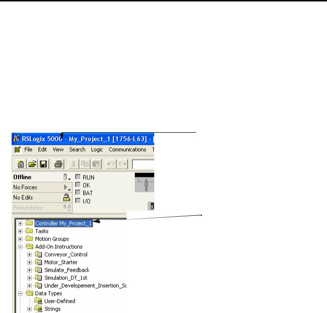
In an open project, there is this information:
A
B
 C
C
Item |
Description |
|
|
A |
Name of the project. If you rename the project or controller, both names are shown. |
|
|
B |
Name of the controller. |
|
|
C |
The controller organizer is a graphical overview of the project. Use the controller organizer |
|
to navigate to the various components of a project. |
|
|
To open a folder and show its contents, either:
•double-click the folder.
•click the + sign.
12 |
Publication 1756-QS001E-EN-P - October 2009 |

Program and Test a Simple Project |
Chapter 1 |
|
|
Follow These Steps
1.Create a project for the controller (page 14).
2.Add I/O modules (page 15).
3.Look at I/O data (page 17).
4.Enter ladder logic (page 19).
5.Enter a function block diagram (page 21).
6.Assign alias tags for your devices (page 25).
7.Establish a serial connection to the controller (page 28).
8.Download a project to the controller (page 30).
9.Select the operating mode of the controller (page 32).
Publication 1756-QS001E-EN-P - October 2009 |
13 |
Chapter 1 Program and Test a Simple Project
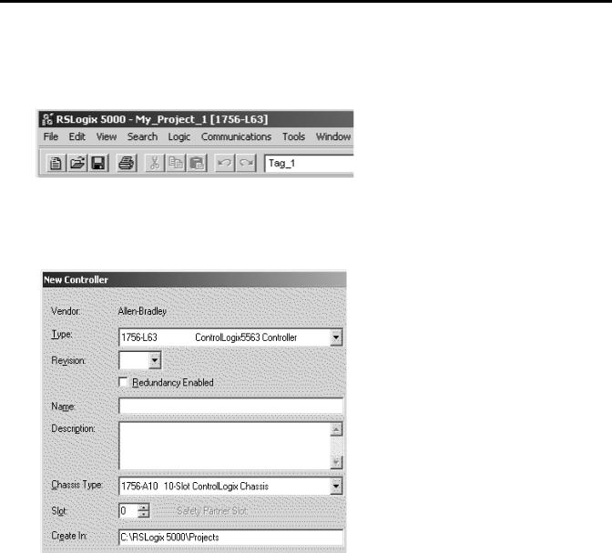
Create a Project for the Controller
1.Start RSLogix 5000 software.
2.Click New.
3.Specify the general configuration for the controller.
Specify these items (some items apply to only certain controllers):
•Type of controller.
•Major revision of firmware for the controller.
•Name for the controller.
•Chassis type for the controller.
•Slot number of the controller.
•The path where the project will be stored.
4.Click OK.
14 |
Publication 1756-QS001E-EN-P - October 2009 |
Program and Test a Simple Project |
Chapter 1 |
|
|
Conventions for Names
Throughout a Logix5000 project, you define names for the different elements of the project, such as the controller, data addresses (tags), routines, and I/O modules. As you enter names, follow these rules.
•Only letters, numbers, and underscores (_)
•Must start with a letter or an underscore
•≤ 40 characters
•No consecutive or trailing underscores
•Not case sensitive
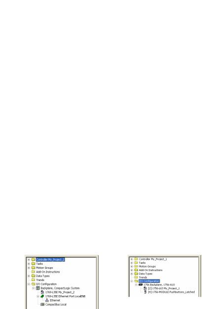
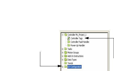
Add Your I/O Modules
To communicate with an I/O modules in your system, you add the modules to the I/O Configuration folder of the controller. The properties you select for each module defines the behavior of the module.
TIP |
The screens shown are representative of three types of controllers; other types are available, but are not |
|
shown here. |
||
|
||
|
1. Right-click the I/O Configuration folder and choose New Module.
CompactLogix |
ControlLogix |
Controller |
Controller |
Publication 1756-QS001E-EN-P - October 2009 |
15 |
Chapter 1 Program and Test a Simple Project
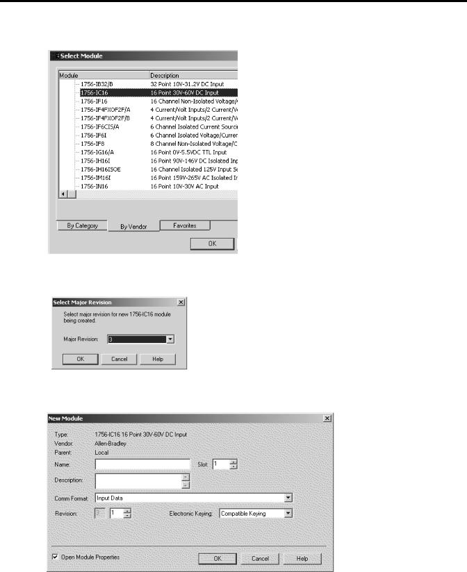
2. Select the module and click OK.
3. From the Major Revision pull-down menu, choose the revision of the module.
4. Define the module and click OK.
16 |
Publication 1756-QS001E-EN-P - October 2009 |
Program and Test a Simple Project |
Chapter 1 |
|
|
Look at Your I/O Data
I/O information is presented as a set of tags.
When you add a module to the I/O
Configuration folder…
…the software automatically creates controller-scoped tags for the module.
An I/O address follows this format.
Location |
|
:Slot |
|
:Type |
|
.Member |
|
.SubMember |
|
.Bit |
|
|
|
|
|
|
|
|
|
|
|
|
|
|
|
|
= Optional |
|
|
|
|
|
|
|
|
|
|
|
|
|
|
|
|
|
|
|
|
|
|
|
|
|
|
|
|
|
|
|
|
|
|
|
|
|
|
|
|
|
|
|
|
|
|||||||||||
Where |
|
Is |
|||||||||||
|
|
|
|||||||||||
Location |
|
Network location |
|||||||||||
|
|
|
LOCAL = same chassis or DIN rail as the controller |
||||||||||
|
|
|
ADAPTER_NAME = identifies remote communication adapter or bridge module |
||||||||||
|
|
|
|||||||||||
Slot |
|
Slot number of I/O module in its chassis or DIN rail |
|||||||||||
|
|
|
|||||||||||
Type |
|
Type of data |
|||||||||||
|
|
|
I = input |
||||||||||
|
|
|
O = output |
||||||||||
|
|
|
C = configuration |
||||||||||
|
|
|
S = status |
||||||||||
|
|
|
|||||||||||
Member |
|
Specific data from the I/O module; depends on what type of data the module can store. |
|||||||||||
|
|
|
|
• For a digital module, a Data member usually stores the input or output bit values. |
|||||||||
|
|
|
|
• For an analog module, a Channel member (CH#) usually stores the data for a channel. |
|||||||||
|
|
|
|||||||||||
SubMember |
|
Specific data related to a Member. |
|||||||||||
|
|
|
|||||||||||
Bit |
|
Specific point on a digital I/O module; depends on the size of the I/O module (0-31 for a 32-point module) |
|||||||||||
|
|
|
|
|
|
|
|
|
|
|
|
|
|
Publication 1756-QS001E-EN-P - October 2009 |
17 |
Chapter 1 Program and Test a Simple Project
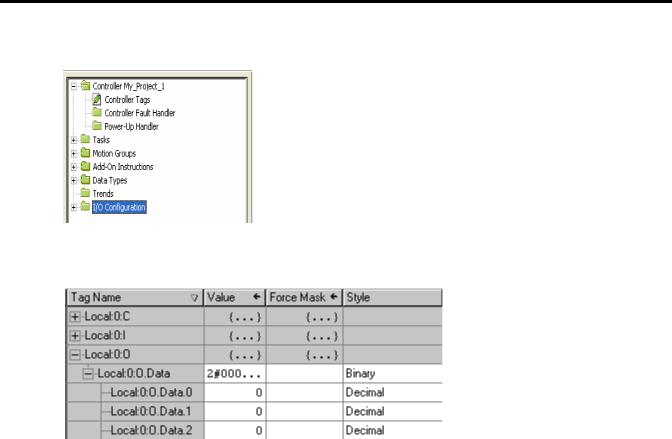
1. Right-click Controller Tags and choose Monitor Tags.
The Tag Monitor displays the tags.
Values are shown in the following styles.
Style |
Base |
Notation |
|
|
|
Binary |
2 |
2# |
|
|
|
Decimal |
10 |
NA |
|
|
|
Hexadecimal |
16 |
16# |
|
|
|
Octal |
8 |
8# |
|
|
|
Exponential |
NA |
0.0000000e+000 |
|
|
|
Float |
NA |
0.0 |
|
|
|
A blue arrow indicates that when you change the value, it immediately takes effect.
2.To see a value in a different style, select the desired style.
3.To change a value, click the Value cell, type the new value, and click Enter.
4.To expand a tag and show its members, click the + sign.
18 |
Publication 1756-QS001E-EN-P - October 2009 |
Program and Test a Simple Project |
Chapter 1 |
|
|
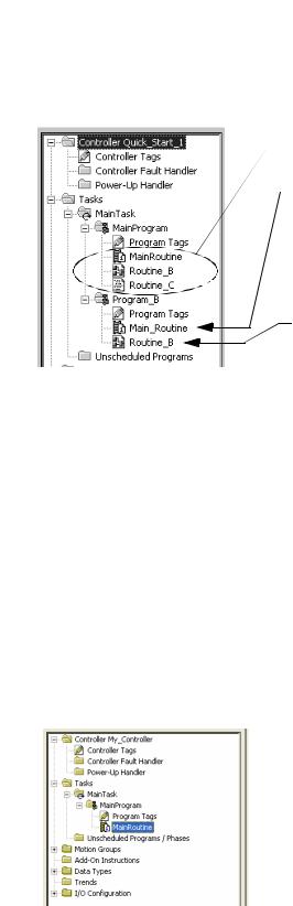
Ladder Logic
For a Logix5000 controller, you enter your logic in routines.
A
 B
B
C
Item |
Description |
|
|
A |
A routine provides the executable code (logic) for a program (similar to a program file in a |
|
PLC or SLC controller). |
|
|
B |
There is one main routine you assign for each program. |
|
• When the program executes, its main routine automatically executes. |
|
• Use the main routine to control the execution of the other routines in the program. |
|
• To call (execute) another routine (subroutine) within the program, use a Jump to |
|
Subroutine (JSR) instruction. |
|
|
C |
A subroutine is any routine other than the main routine or fault routine. To execute a |
|
subroutine, use a Jump to Subroutine (JSR) instruction in another routine, such as the main |
|
routine. |
|
|
When you create a project, the software automatically creates a main routine that uses the ladder diagram programming language.
Publication 1756-QS001E-EN-P - October 2009 |
19 |

Chapter 1 Program and Test a Simple Project
Enter Ladder Logic
One way to enter logic is to drag buttons from a toolbar to the desired location.
A green dot shows a valid placement location (drop point).
To add ladder logic, drag the button for the rung or instruction directly to the desired location. You can enter your logic and leave the operands undefined. After you enter a section of logic, go back and assign the operands.
|
In the following example, an Examine If Closed (XIC) instruction checks the on/off state of a pushbutton. If |
|
EXAMPLE |
||
the pushbutton is on, the Output Energize (OTE) instruction turns on a light. |
||
|
||
|
XIC |
OTE |
||
If this bit is on… |
…turn on this bit. Otherwise, |
||
|
|
turn off this bit. |
|
|
|
||
|
|
|
|
|
|
|
|
20 |
Publication 1756-QS001E-EN-P - October 2009 |
Program and Test a Simple Project |
Chapter 1 |
|
|
Enter a Function Block Diagram
Follow these steps to add a function block diagram to your project.
Create a Routine
Each routine in your project uses a specific programming language. To program in a different language, such as function block diagram, create a new routine.
1. Right-click MainProgram and choose New Routine.
2. Type a name for the routine.
3.Choose the programming language.
4.Click OK.
Publication 1756-QS001E-EN-P - October 2009 |
21 |
Chapter 1 Program and Test a Simple Project
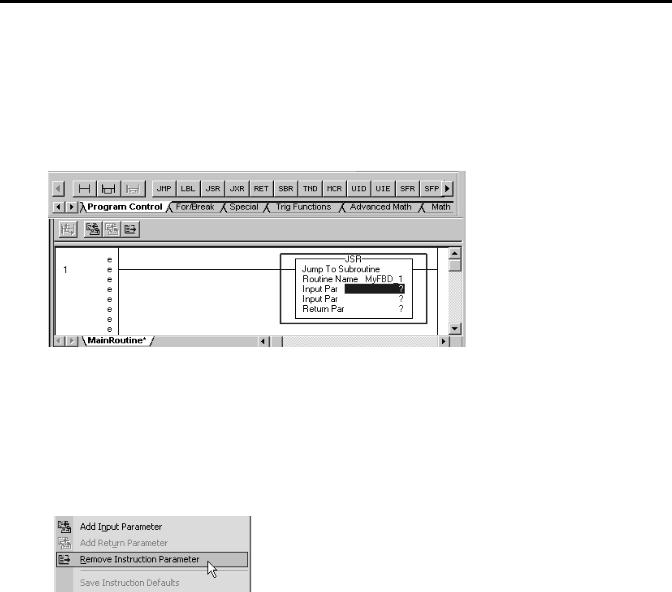
Call the Routine
To execute a routine other than the main routine, use a Jump to Subroutine (JSR) instruction to call the routine.
1. Add a rung.
2.On the Program Control tab, add a JSR instruction.
3.In the Routine Name field of the JSR instruction, type the name of the routine that you want to execute.
4.To simply call the routine, remove the rest of the parameters for the JSR instruction. To remove a parameter, right-click the parameter and choose Remove Instruction Parameter.
22 |
Publication 1756-QS001E-EN-P - October 2009 |
Program and Test a Simple Project |
Chapter 1 |
|
|
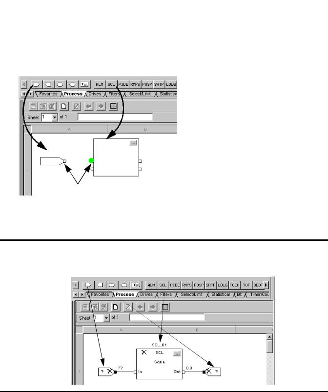
Enter a Function Block Diagram
Enter function block diagram instructions in a function block routine.
1. Click the tab for the desired instructions.
2.Drag elements from the toolbar to the sheet.
3.To connect elements, click corresponding pins (green dot = valid connection point).
EXAMPLE |
In the following example, an Input Reference (IREF) reads the value of an analog input and sends the value |
|
to a Scale (SCL) instruction. The SCL instruction converts the value to engineering uses and sends it to an |
||
|
||
|
||
|
Output Reference (OREF). The OREF writes the value to an analog output. |
Publication 1756-QS001E-EN-P - October 2009 |
23 |
Chapter 1 Program and Test a Simple Project
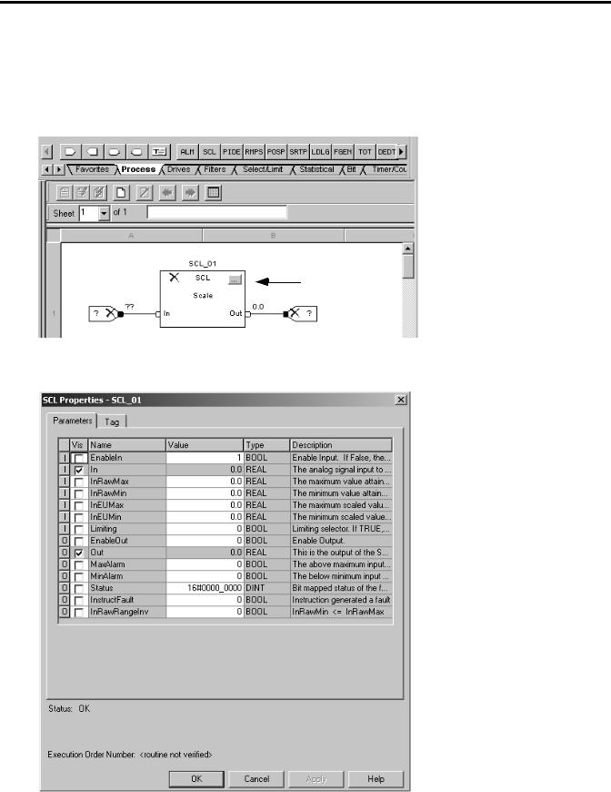
Configure a Function Block Instruction
Assign specific values (parameters) to configure a function block instruction.
1. Click the configuration button.
2. To change the value of a parameter, click the value cell, type the new value, and click Enter.
24 |
Publication 1756-QS001E-EN-P - October 2009 |
Program and Test a Simple Project |
Chapter 1 |
|
|
For example, in the SCL instruction, specify the following parameters:
•InRawMax – maximum input value
•InRawMin – minimum input value
•InEUMax – maximum engineering value
•InEUMin – minimum engineering value
3.Click OK.
Assign Alias Tags for Your Devices
While you can use the input and output tags of a module directly in your logic, it is easier to use alias tags. An alias tag is a tag that represents another tag.
•Both tags share the same data.
•When the data changes, both tags change.
•An alias tag provides a descriptive name for data, such as DeviceNet input or output data.
•If the location of the data changes, simply point the alias tag goes to the new location without editing your logic.
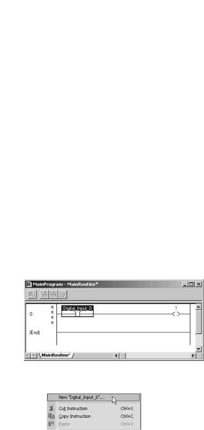
As an option, create tags that describe each device without pointing them to the actual addresses of the devices. Later, convert the tags to aliases for the data of the devices.
1.Enter the logic.
2.Type a descriptive tag name for the device.
3. Right-click the tag name and choose New…
Publication 1756-QS001E-EN-P - October 2009 |
25 |
Chapter 1 Program and Test a Simple Project
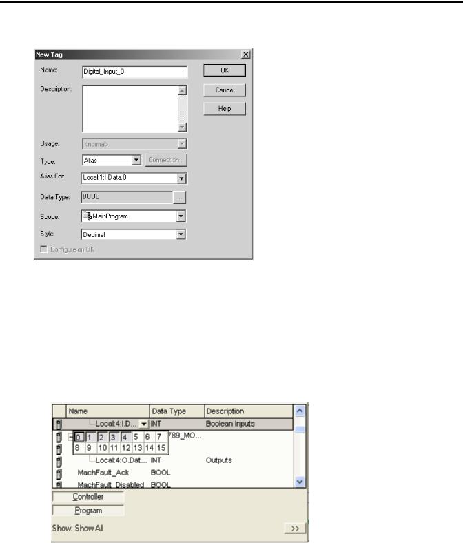
4. Select Alias from the menu.
5.Select the tag that this alias tag represents.
6.Select the scope for the alias tag.
7.Click OK.
8.Select the address of the data.
To select a bit, click the b button.
26 |
Publication 1756-QS001E-EN-P - October 2009 |
Program and Test a Simple Project |
Chapter 1 |
|
|
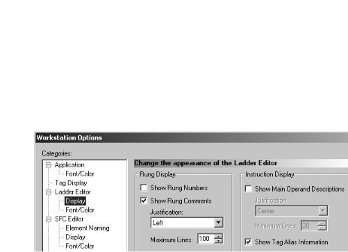
Show or Hide Alias Information
Show or hide alias information for a tag.
1.From the Tools menu, choose Options.
2.Select the Ladder Editor Display category.
3.Check or uncheck Show Tag Alias Information.
4.Click OK.
Publication 1756-QS001E-EN-P - October 2009 |
27 |

Chapter 1 Program and Test a Simple Project
Establish a Serial Connection to the Controller
RSLinx Classic software handles communication between Logix5000 controllers and your software programs, such as RSLogix 5000 software. To communicate with a controller (for example, download, monitor data), configure RSLinx Classic software for the required communication.
Logix5000 Controller |
|
|
|
RSLinx Classic Software |
|
|
|
|
|
|
|
|
|
|
RSLogix 5000 Software |
||
|
|
|
|
|
|
|||
|
|
|
|
|
|
|
|
|
|
|
|
|
|
|
|
|
|
|
|
|
|
|
|
|
|
|
Driver – establish communication over a specific network.
 Path – communication route to a device. To define a path, you expand a driver and select the device.
Use a serial cable to establish a point-to-point connection between the serial ports on your computer and controller.
WARNING
If you connect or disconnect the serial cable with power applied to this module or the serial device on the other end of the cable, an electrical arc can occur. This could cause an explosion in hazardous location installations.
Be sure that power is removed or the area is nonhazardous before proceeding.
1. Connect a serial cable to your controller and computer.
Logix5000
Controller
1756-CP3 or 1747-CP3 serial cable
28 |
Publication 1756-QS001E-EN-P - October 2009 |
Program and Test a Simple Project |
Chapter 1 |
|
|
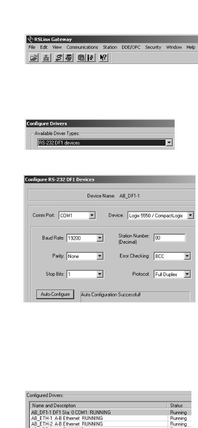
2.Start RSLinx Classic software.
3.Click  .
.
4.Select RS-232 DF1 devices and click  .
.
5.From the Comm Port pull-down menu, choose the COM port of your computer.
6.From the Device pull-down menu, choose Logix 5550/CompactLogix.
7.Click  .
.
8.When the auto-configuration completes, click OK. The driver is successfully configured and running.
Publication 1756-QS001E-EN-P - October 2009 |
29 |
Chapter 1 Program and Test a Simple Project
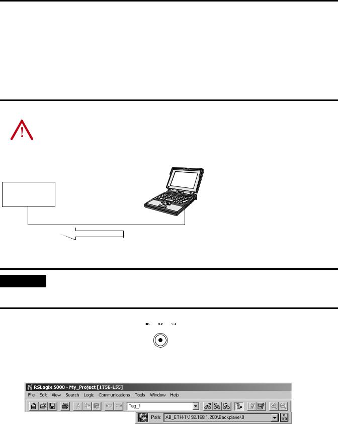
Download a Project to the Controller
To execute a project in a controller, download the project to the controller to transfer a project from your computer to the controller so you can run the project. When you download a project, you lose the project and data that is currently in the controller, if any. If the revision of the controller does not match the revision of the project, you are prompted to update the firmware of the controller. RSLogix 5000 software lets you update the firmware of the controller as part of the download sequence.
ATTENTION |
When you download a project or update firmware, all active servo axes are turned off. Before you |
|||
download a project or update firmware, make sure that this will not cause any unexpected movement of an |
||||
|
|
|
||
|
|
|
||
|
|
|
axis. |
|
|
|
|
|
|
|
|
|
|
|
|
|
|
|
|
Logix5000
Controller
Project
Download
|
To update the firmware of a controller, first install a firmware upgrade kit. |
|
IMPORTANT |
||
|
•An upgrade kit ships on a supplemental CD along with RSLogix 5000 software.
•To download an upgrade kit, go to http://www.ab.com. Choose Product Support. Choose Firmware Updates.
|
|
|
|
|
|
|
|
|
|
|
|
|
|
1. Turn the keyswitch of the controller to |
|
. |
||||
|
||||||
2.Open the RSLogix 5000 project that you want to download.
3.Click  .
.
30 |
Publication 1756-QS001E-EN-P - October 2009 |
Loading...