


 Loading...
Installation Instructions
CompactLogix 5370 L2 Controllers
Catalog Numbers 1769-L24ER-QB1B, 1769-L24ER-QBFC1B,
1769-L27ERM-QBFC1B
Prevent Electrostatic Discharge
This equipment is sensitive to electrostatic discharge, which can cause internal damage and affect normal operation. Follow these guidelines when you handle this equipment:
•Touch a grounded object to discharge potential static.
•Wear an approved grounding wriststrap.
•Do not touch connectors or pins on component boards.
•Do not touch circuit components inside the equipment.
•Use a static-safe workstation, if available.
•Store the equipment in appropriate static-safe packaging when not in use.
Before You Begin
Consider the following before installing a CompactLogix 5370 L2 controller:
•The control system includes a controller, an embedded power supply, and embedded I/O points.
•The embedded power supply is a 24V DC input, isolated power supply.
•You must connect an external Class 2 or SELV-approved power supply to provide 24V DC power to the system.
•The controllers have embedded I/O points. You wire the input and output points via a removable connector.
•The controller supports the use of Compact I/O modules on the local
1769 CompactBus backplane as local expansion modules.
•You must terminate the end of the CompactBus via a 1769-ECR right end cap.
2 CompactLogix 5370 L2 Controllers
•You cannot remove nor install Compact I/O modules while the controller is powered.
ATTENTION: CompactLogix 5370 L2 control systems do not support removal and insertion under power (RIUP). Removing a 1769 Compact I/O module or end cap will generate a controller fault and may also result in damage to system components.
Install the Secure Digital Card
The CompactLogix 5370 L2 controller is shipped from the factory with the
1784-SD1 SD card installed.
Complete these steps to re-install an SD card that has been removed from the controller back into the controller or if installing a new SD card into the controller.
WARNING: When you insert or remove the SD card while power is on, an electrical arc can occur. This could cause an explosion in hazardous location installations.
Be sure that power is removed or the area is nonhazardous before proceeding.
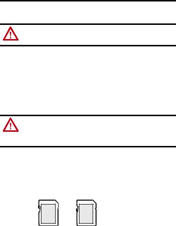
1.Verify that the SD card is locked or unlocked according to your preference before installation. Consider the following points:
–If the card is unlocked, the controller can write data to it or read data from it.
–If the card is locked, the controller can only read data from it.
Unlocked |
Locked |
32005-M
Rockwell Automation Publication 1769-IN090A-EN-P - April 2012
CompactLogix 5370 L2 Controllers 3
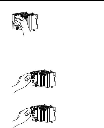
2. Open the door for the SD card.
32253-M
3.Insert the SD card into the SD card slot.
You can install the SD card in one orientation only. The beveled corner should be at the bottom. If you feel resistance when inserting the SD card, pull it out and change the orientation.
4.Gently press the card until it clicks into place.
32254-M
5. Close the SD card door.
32255-M
We recommend you close the SD card door during system operation.
Rockwell Automation Publication 1769-IN090A-EN-P - April 2012
4 CompactLogix 5370 L2 Controllers
Mount the System
Mount a CompactLogix 5370 L2 control system on a DIN rail or a panel.
WARNING: When used in a Class I, Division 2, hazardous location, this equipment must be mounted in a suitable enclosure with proper wiring method that complies with the governing electrical codes.
Available DIN Rails
ATTENTION: This product is grounded through the DIN rail to chassis ground. Use zinc-plated yellow-chromate steel DIN rail to assure proper grounding. The use of other DIN rail materials (for example, aluminum or plastic) that can corrode, oxidize, or are poor conductors, can result in improper or intermittent grounding. Secure DIN rail to mounting surface approximately every 200 mm (7.8 in.) and use end-anchors appropriately.
You can mount the CompactLogix 5370 L2 controller on these DIN rails:
•EN 50 022 - 35 x 7.5 mm (1.38 x 0.30 in.)
•EN 50 022 - 35 x 15 mm (1.38 x 0.59 in.)
Rockwell Automation Publication 1769-IN090A-EN-P - April 2012

CompactLogix 5370 L2 Controllers 5
Minimum Spacing
Maintain spacing from enclosure walls, wireways, and adjacent equipment. Allow 50 mm (2 in.) of space on all sides, as shown. This provides ventilation and electrical isolation.
Side
50 mm (2 in.)
|
Top |
|
|
50 mm |
||||
|
|
|
||||||
|
|
|
(2 in.) |
|
|
|||
|
|
|
|
|
|
|||
|
|
|
|
|
|
|
|
|
|
CompactLogix 5370 L2 Controller with Embedded Power Supply and I/O Points |
Compact I/O Module |
Compact I/O Module |
Compact I/O Module |
|
Compact I/O Module |
End Cap |
|
|
|
|
|
|
|
|
|
|
|
Bottom |
|
|
50 mm |
||||
|
|
|
||||||
|
|
|
(2 in.) |
|
|
|||
|
|
|
|
|
|
|||
|
|
|
|
|
|
|
|
|
Side
50 mm (2 in.)
System Dimensions
This graphic shows system dimensions for the 1769-L24ER-QB1B controller.
105.00 mm |
|
|
115.00 mm |
|
35.00 mm (1.38 in.) |
||||||||||
|
|
(4.53 in.) |
|
|
|
|
|
||||||||
|
|
|
|
|
|
|
|
|
|
|
|
|
|
|
|
|
|
|
|
|
|
|
|
|
|
|
|
|
|
||
(4.13 in.) |
|
|
|
|
|
|
|
||||||||
|
|
|
|
|
|
|
|
|
|||||||
|
|
|
|
|
|
|
|
|
|
|
|
|
|
|
|
118.00 mm
(4.65 in.)
|
L24ER |
0 |
1 |
2 |
3 |
4 |
5 |
6 |
7 |
|
QB1B |
8 |
9 |
10 |
11 |
12 |
13 |
14 |
15 |
|
|
0 |
1 |
2 |
3 |
4 |
5 |
6 |
7 |
|
|
8 |
9 |
10 |
11 |
12 |
13 |
14 |
15 |
|
00 |
08 |
|
|
|
|
|
|
|
|
01 |
09 |
|
|
|
|
|
|
|
|
02 |
10 |
|
|
|
|
|
|
|
|
03 |
11 |
|
|
|
|
|
|
|
|
04 |
12 |
|
|
|
|
|
|
|
|
05 |
13 |
|
|
|
|
|
|
|
|
06 |
14 |
|
|
|
|
|
|
|
|
07 |
15 |
|
|
|
|
|
|
|
|
COM COM |
|
|
|
|
|
|
|
|
|
0 |
1 |
|
|
|
|
|
|
|
|
NC NC |
|
|
|
|
|
|
|
|
|
+V |
+V |
|
|
|
|
|
|
|
|
00 |
08 |
|
|
|
|
|
|
|
|
01 |
09 |
|
|
|
|
|
|
|
|
02 |
10 |
|
|
|
|
|
|
|
|
03 |
11 |
|
|
|
|
|
|
|
00:00:BC:2E:69:F6 |
04 |
12 |
|
|
|
|
|
|
|
05 |
13 |
|
|
|
|
|
|
|
|
|
06 |
14 |
|
|
|
|
|
|
|
|
07 |
15 |
|
|
|
|
|
|
|
|
COM COM |
|
|
|
|
|
|
|
|
|
0 |
1 |
|
|
|
|
|
|
|
+24VDC COM FG
Rockwell Automation Publication 1769-IN090A-EN-P - April 2012
Loading...