


 Loading...
Installation Instructions
CompactLogix Packaged Controllers
Catalog Numbers 1769-L23E-QB1B, 1769-L23E-QBFC1B, 1769-L23-QBFC1B
Topic |
Page |
|
|
|
|
|
|
Important User Information |
2 |
|
|
|
|
|
|
Verify Compatibility |
6 |
|
|
|
|
||
|
|
|
|
Before You Begin |
6 |
|
|
|
|
|
|
Installation Checklist |
8 |
|
|
|
|
|
|
Packaged Controller Dimensions |
9 |
|
|
|
|
|
|
Install the Battery |
11 |
|
|
|
|
|
|
Connect Expansion Modules (optional) |
12 |
|
|
|
|
|
|
Panel Mount the System |
14 |
|
|
|
|
|
|
DIN-rail Mount the System |
14 |
|
|
|
|
|
|
Grounding Considerations |
15 |
|
|
|
|
|
|
Wiring Power to the System |
15 |
|
|
|
|
|
|
Wire the I/O Removable Terminal Blocks |
17 |
|
|
|
|
|
|
Connect Using the RS-232 Connection |
28 |
|
|
|
|
|
|
Connect Using the Ethernet Connection |
28 |
|
|
|
|
|
|
Download and Install EDS Files |
29 |
|
|
|
|
|
|
Download Packaged Controller Firmware |
29 |
|
|
|
|
|
|
Use the AutoFlash Feature of RSLogix 5000 Software to Load Firmware |
29 |
|
|
|
|
|
|
Use the ControlFLASH Utility to Load Firmware |
33 |
|
|
|
|
|
|
Select the Packaged Controller’s Operating Mode |
35 |
|
|
|
|
|
|
Power Supply Status Indicator |
36 |
|
|
|
|
|
|
Controller Status Indicators |
36 |
|
|
|
|
|
|
Additional Resources |
42 |
|
|
|
|
|
|
Use this document as a guide to install the CompactLogix™ packaged controllers.
2 CompactLogix Controller
Important User Information
Solid-state equipment has operational characteristics differing from those of electromechanical equipment. Safety Guidelines for the Application, Installation and Maintenance of Solid State Controls (Publication SGI-1.1 available from your local Rockwell Automation® sales office or online at http://www.rockwellautomation.com/literature/) describes some important differences between solid-state equipment and hard-wired electromechanical devices. Because of this difference, and also because of the wide variety of uses for solid-state equipment, all persons responsible for applying this equipment must satisfy themselves that each intended application of this equipment is acceptable.
In no event will Rockwell Automation, Inc. be responsible or liable for indirect or consequential damages resulting from the use or application of this equipment.
The examples and diagrams in this manual are included solely for illustrative purposes. Because of the many variables and requirements associated with any particular installation, Rockwell Automation, Inc. cannot assume responsibility or liability for actual use based on the examples and diagrams.
No patent liability is assumed by Rockwell Automation, Inc. with respect to use of information, circuits, equipment, or software described in this manual.
Reproduction of the contents of this manual, in whole or in part, without written permission of Rockwell Automation, Inc., is prohibited.
Throughout this manual, when necessary, we use notes to make you aware of safety considerations.
WARNING: Identifies information about practices or circumstances that can cause an explosion in a hazardous environment, which may lead to personal injury or death, property damage, or economic loss.
ATTENTION: Identifies information about practices or circumstances that can lead to personal injury or death, property damage, or economic loss. Attentions help you identify a hazard, avoid a hazard and recognize the consequences.
SHOCK HAZARD: Labels may be on or inside the equipment, for example, drive or motor, to alert people that dangerous voltage may be present.
BURN HAZARD: Labels may be on or inside the equipment, for example, drive or motor, to alert people that surfaces may reach dangerous temperatures.
IMPORTANT Identifies information that is critical for successful application and understanding of the product.
Rockwell Automation Publication 1769-IN082C-EN-P - February 2013
CompactLogix Controller 3
Environment and Enclosure
WARNING: This equipment is intended for use in a Pollution Degree 2 industrial environment, in overvoltage Category II applications (as defined in IEC publication 60664-1), at altitudes up to 2000 meters (6562 ft) without derating.
This equipment is considered Group 1, Class A industrial equipment according to IEC/CISPR Publication 11. Without appropriate precautions, there may be potential difficulties ensuring electromagnetic compatibility in other environments due to conducted as well as radiated disturbance.
This equipment is supplied as open-type equipment. It must be mounted within an enclosure that is suitably designed for those specific environmental conditions that will be present and appropriately designed to prevent personal injury resulting from accessibility to live parts. The enclosure must have suitable flame-retardant properties to prevent or minimize the spread of flame, complying with a flame spread rating of 5VA, V2, V1, V0 (or equivalent) if non-metallic. The interior of the enclosure must be accessible only by the use of a tool. Subsequent sections of this publication may contain additional information regarding specific enclosure type ratings that are required to comply with certain product safety certifications.
In addition to this publication, see the following:
•Industrial Automation Wiring and Grounding Guidelines, Allen-Bradley® publication 1770-4.1, for additional installation requirements
•NEMA Standards publication 250 and IEC publication 60529, as applicable, for explanations of the degrees of protection provided by different types of enclosure
Prevent Electrostatic Discharge
WARNING: This equipment is sensitive to electrostatic discharge, which can cause internal damage and affect normal operation. Follow these guidelines when you handle this equipment:
• Touch a grounded object to discharge potential static.
• Wear an approved grounding wrist-strap.
• Do not touch connectors or pins on component boards.
• Do not touch circuit components inside the equipment.
• Use a static-safe workstation, if available.
• Store the equipment in appropriate static-safe packaging when not in use.
Rockwell Automation Publication 1769-IN082C-EN-P - February 2013
4 CompactLogix Controller
North American Hazardous Location Approval
The following information applies when operating this |
Informations sur l’utilisation de cet équipement en |
||||||
equipment in hazardous locations. |
environnements dangereux. |
||||||
|
|
|
|
|
|
||
|
Products marked "CL I, DIV 2, GP A, B, C, D" are |
|
Les produits marqués "CL I, DIV 2, GP A, B, C, D" ne |
||||
|
|
conviennent qu'à une utilisation en environnements de |
|||||
|
suitable for use in Class I Division 2 Groups A, B, C, D, |
|
|||||
|
|
Classe I Division 2 Groupes A, B, C, D dangereux et non |
|||||
|
Hazardous Locations and nonhazardous locations |
|
|||||
|
|
dangereux. Chaque produit est livré avec des |
|||||
|
only. Each product is supplied with markings on the |
|
|||||
|
|
marquages sur sa plaque d'identification qui indiquent |
|||||
|
rating nameplate indicating the hazardous location |
|
|||||
|
|
le code de température pour les environnements |
|||||
|
temperature code. When combining products |
|
|||||
|
|
dangereux. Lorsque plusieurs produits sont combinés |
|||||
|
within a system, the most adverse temperature |
|
|||||
|
|
dans un système, le code de température le plus |
|||||
|
code (lowest "T" number) may be used to help |
|
|||||
|
|
défavorable (code de température le plus faible) peut |
|||||
|
determine the overall temperature code of the |
|
|||||
|
|
être utilisé pour déterminer le code de température |
|||||
|
system. Combinations of equipment in your system |
|
|||||
|
|
global du système. Les combinaisons d'équipements |
|||||
|
are subject to investigation by the local Authority |
|
|||||
|
|
dans le système sont sujettes à inspection par les |
|||||
|
Having Jurisdiction at the time of installation. |
|
|||||
|
|
autorités locales qualifiées au moment de l'installation. |
|||||
|
|
|
|
|
|||
|
|
|
|
|
|
|
|
|
|
|
WARNING: |
|
|
|
AVERTISSEMENT: |
|
|
|
Explosion Hazard - |
|
|
|
Risque d’Explosion – |
|
|
|
• Do not disconnect equipment unless |
|
|
|
• Couper le courant ou s'assurer que |
|
|
|
power has been removed or the area is |
|
|
|
l'environnement est classé non dangereux |
|
|
|
|||||
|
|
|
known to be nonhazardous. |
|
|
|
avant de débrancher l'équipement. |
|
|
|
• Do not disconnect connections to this |
|
|
|
• Couper le courant ou s'assurer que |
|
|
|
equipment unless power has been |
|
|
|
l'environnement est classé non dangereux |
|
|
|
removed or the area is known to be |
|
|
|
avant de débrancher les connecteurs. Fixer |
|
|
|
nonhazardous. Secure any external |
|
|
|
tous les connecteurs externes reliés à cet |
|
|
|
connections that mate to this equipment |
|
|
|
équipement à l'aide de vis, loquets |
|
|
|
by using screws, sliding latches, |
|
|
|
coulissants, connecteurs filetés ou autres |
|
|
|
threaded connectors, or other means |
|
|
|
moyens fournis avec ce produit. |
|
|
|
provided with this product. |
|
|
|
• La substitution de composants peut rendre |
|
|
|
• Substitution of components may impair |
|
|
|
cet équipement inadapté à une utilisation en |
|
|
|
suitability for Class I, Division 2. |
|
|
|
environnement de Classe I, Division 2. |
|
|
|
• If this product contains batteries, they |
|
|
|
• S'assurer que l'environnement est classé non |
|
|
|
must only be changed in an area known |
|
|
|
dangereux avant de changer les piles. |
|
|
|
to be nonhazardous. |
|
|
|
|
|
|
|
|
|
|
|
|
Rockwell Automation Publication 1769-IN082C-EN-P - February 2013
CompactLogix Controller 5
European Hazardous Location Approval
European Zone 2 Certification (The following applies when the product bears the Ex or EEx Marking.)
This equipment is intended for use in potentially explosive atmospheres as defined by European Union Directive 94/9/EC and has been found to comply with the Essential Health and Safety Requirements relating to the design and construction of Category 3 equipment intended for use in potentially explosive atmospheres, given in Annex II to this Directive.
Compliance with the Essential Health and Safety Requirements has been assured by compliance with EN 60079-15 and EN 60079-0.
WARNING:
• This equipment must be installed in an enclosure providing at least IP54 protection when applied in Zone 2 environments.
•This equipment shall be used within its specified ratings defined by Allen-Bradley.
•Provisions shall be made to prevent the rated voltage from being exceeded by transient disturbances of more than 40% when applied in Zone 2 environments.
•Secure any external connections that mate to this equipment by using screws, sliding latches, threaded connectors, or other means provided with this product.
•Do not disconnect equipment unless power has been removed or the area is known to be nonhazardous.
ATTENTION: This equipment is not resistant to sunlight or other sources of UV radiation.
Rockwell Automation Publication 1769-IN082C-EN-P - February 2013

6 CompactLogix Controller
Verify Compatibility
IMPORTANT The series B controllers are compatible only with the controller firmware and the RSLogix 5000 software versions as indicated in the table below.
Attempting to use controllers with incompatible software and firmware revisions can result in the following:
•An inability to connect to the series B controller in RSLogix 5000 software
•Unsuccessful firmware upgrades in ControlFLASH™ or AutoFlash utilities
This table shows the compatible pairs of RSLogix 5000 software versions and controller firmware revisions.
|
|
Controller |
RSLogix 5000 Software Version or Later |
Controller Firmware Revision or Later |
|
|
|||
|
|
|
|
|
|
|
1769-L23E-QB1B, |
16.00.00 |
16.023 |
|
|
|||
|
|
1769-L23E-QBFC1B, |
|
|
|
|
17.01.02 |
17.012 |
|
|
|
1769-L23-QBFC1B |
||
|
|
|
|
|
|
|
|
19.01.00 |
19.015 |
|
|
|
||
|
|
|
|
|
|
|
|
20.01.00 |
20.013 |
|
|
|
||
|
|
|
|
|
Before You Begin
This section contains information you should understand before installing the CompactLogix packaged controller.
Restrictions
The maximum amount of expansion modules that can be used with the packaged controllers is two. Within that limit, the number of expansion I/O modules that can be attached to the packaged controller depends on the bus current draw of the modules being attached.
Each packaged controller has a specified amount of available bus current as shown in this table.
Packaged Controller Bus Current and Expansion Module Limits
Cat. No. |
Total Available 5V DC Bus Current |
|
|
1769-L23E-QB1B |
1 A (1000 mA) |
|
|
1769-L23E-QBFC1B |
450 mA |
|
|
1769-L23-QBFC1B |
800 mA |
|
|
To determine the number of expansion I/O modules you can add, total the bus current draw (maximum) of your planned expansion I/O modules and the end cap. If your result is less than
Rockwell Automation Publication 1769-IN082C-EN-P - February 2013

CompactLogix Controller 7
the packaged controller’s maximum available bus current, you are within the expansion I/O limit of your packaged controller.
Example of Expansion I/O Calculation
In this example, these expansion I/O modules and bus current draws are planned for use with the 1769-L23E-QBFC1B packaged controller.
Planned Expansion I/O Module |
Bus Current Draw, max(1) |
1769-OV16 Sink Output Module |
200 mA |
|
|
1769-IF4 Analog Input Module |
105 mA |
|
|
1769-ECR End Cap |
5 mA |
|
|
Total Bus Current Draw |
310 mA |
|
|
(1)The maximum bus current draw specification for each Compact I/O™ module is available in the Compact I/O Selection Guide, publication 1769-SG002. This publication also provides further explanation of and a table for the calculation of Compact I/O power supply requirements.
The total bus current draw of the Compact I/O modules (310 mA) is less than the total available bus current of the packaged controller (450 mA). These planned expansion I/O modules are within the limits of the 1769-L23E-QBFC1B packaged controller.
Parts (included with the controller)
These components are included with your CompactLogix packaged controller.
Cat. No. |
Part |
|
|
1747-KY |
Key |
|
|
1769-BA |
Battery |
|
|
1769-ECR |
End cap |
|
|
Parts (optional, not included with the controller)
In addition to the parts included with the packaged controller, you may choose to use these components specific to your application.
If using |
Then use this component |
|
|
RS-232 port to connect to the packaged controller. |
1756-CP3 or 1747-CP3 serial cable. |
|
|
EtherNet/IP port to connect to the packaged controller. |
Standard Ethernet cable with an RJ45 connector, or, for industrial |
|
grade requirements, 1585J Ethernet connectivity media. |
|
|
Panel mount method to install the packaged controller. |
4…8 M4 or #8 panhead screws (depending on the number of |
|
expansion modules used). |
|
|
Rockwell Automation Publication 1769-IN082C-EN-P - February 2013

8 CompactLogix Controller
Replacement Parts
These CompactLogix packaged controller replacement parts are available for order.
Catalog No. |
Description |
Compatible Packaged Controllers |
|
|
|
1769-BA |
CompactLogix controller battery |
1769-L23E-QB1B, 1769-L23E-QBFC1B, and |
|
|
1769-L23-QBFC1B |
|
|
|
1769-ECR |
Compact right end cap |
1769-L23E-QB1B, 1769-L23E-QBFC1B, and |
|
|
1769-L23-QBFC1B |
|
|
|
1769-RDQB |
CompactLogix packaged controller door |
1769-L23E-QB1B |
|
|
|
1769-RDQBFC |
CompactLogix packaged controller door |
1769-L23E-QBFC1B and 1769-L23-QBFC1B |
|
|
|
Required Tools
The only tool required for the installation of the CompactLogix packaged controller is a medium-sized Phillips-head screwdriver.
Installation Checklist
This table lists tasks that must be completed to fully install and begin using your packaged controller.
Installation Tasks
Install the Battery
Connect Expansion Modules (optional)
Panel Mount the System or DIN-rail Mount the System Grounding Considerations
Wiring Power to the System
Wire the I/O Removable Terminal Blocks Connect Using the RS-232 Connection Connect Using the Ethernet Connection Download and Install EDS Files Download Packaged Controller Firmware
Use the AutoFlash Feature of RSLogix 5000 Software to Load Firmware or Use the ControlFLASH Utility to Load Firmware
Rockwell Automation Publication 1769-IN082C-EN-P - February 2013
CompactLogix Controller 9
Packaged Controller Dimensions
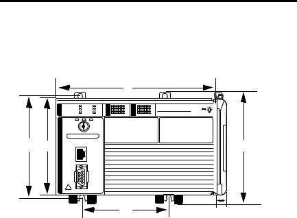
1769-L23E-QB1B Packaged Controller
The 1769-L23E-QB1B controller has these approximate dimensions.
|
|
a |
|
|
CompactLogix L23E |
b |
c |
d |
|
e |
f |
Measurement |
Dimension, approximate |
|
|
a |
185.2 mm (7.29 in.) |
|
|
b |
123.86 mm (4.88 in.) |
|
|
c |
118 mm (4.65 in.) |
|
|
d |
132 mm (5.20 in.) |
|
|
e |
132.9 mm (5.23 in.) |
|
|
f |
18 mm (0.71 in.) |
|
|
Rockwell Automation Publication 1769-IN082C-EN-P - February 2013
10 CompactLogix Controller
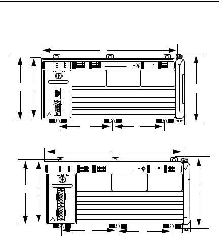
1769-L23E-QBFC1B and 1769-L23-QBFC1B Packaged Controllers |
|
|||
The 1769-L23E-QBFC1B and 1769-L23-QBFC1B packaged controllers have these |
||||
approximate dimensions. |
|
|
|
|
|
|
|
a |
|
|
|
|
CompactLogix L23E |
|
b |
c |
|
|
d |
|
|
e |
f |
g |
|
|
|
a |
|
|
RUN |
I/O |
CompactLogix L23 |
|
|
FORCE |
OK |
|
|
BATT |
DCH 0 |
b |
d |
c
e |
f |
g |
|
|
Measurement(1) |
Dimension, approximate |
a |
249.25 mm (9.81 in.) |
|
|
b |
123.86 mm (4.88 in.) |
|
|
c |
118 mm (4.65 in.) |
|
|
d |
132 mm (5.20 in.) |
|
|
e |
98.475 mm (3.88 in.) |
|
|
f |
98.475 mm (3.88 in.) |
|
|
g |
18 mm (0.71 in.) |
|
|
(1)Applies to both the 1769-L23E-QBFC1B and 1769-L23-QBFC1B packaged controllers.
Rockwell Automation Publication 1769-IN082C-EN-P - February 2013
CompactLogix Controller 11
Minimum Spacing Requirements
When using any of the CompactLogix packaged controllers, maintain spacing from enclosure walls, wireways, and adjacent equipment. Allow 50 mm (1.97 in.) of space on all sides, as shown. This provides ventilation and electrical isolation.
50 mm
(1.97 in.)
50 mm
(1.97 in.)
FORCE |
OK |
CompactLogix L23 |
50 mm |
RUN |
I/O |
|
|
BATT |
DCH 0 |
|
|
|
|
|
|
|
|
|
(1.97 in.) |
50 mm
(1.97 in.)
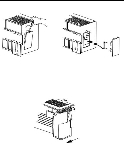
Install the Battery
Complete these steps to install the battery on your packaged controller.
WARNING: When you connect or disconnect the battery an electrical arc can occur. This could cause an explosion in hazardous location installations. Be sure that the area is nonhazardous before proceeding.
For Safety information on the handling of lithium batteries, including handling and disposal of leaking batteries, see Guidelines for Handling Lithium Batteries, publication AG 5-4.
1.Open the battery door on the left side of the packaged controller.
2.Carefully attach the battery connector to the port located inside the packaged controller.
3.Insert the battery, wires down, in the slot on the battery door.
Rockwell Automation Publication 1769-IN082C-EN-P - February 2013
12CompactLogix Controller
4.Close the battery door.
Connect Expansion Modules (optional)
If using expansion modules with your packaged controller, complete these steps to attach the modules.
1. Remove the end cap by unlocking it and sliding it forward.
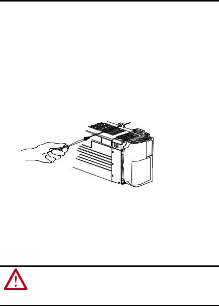
2.Align the tongue-and-groove slots of the expansion module with those on the right end of the packaged controller.
3.Slide the module onto the packaged controller.
Rockwell Automation Publication 1769-IN082C-EN-P - February 2013

CompactLogix Controller 13
4. Close the locking tab on the top of the module.
5.If using another expansion module, complete steps 2…4 for the second module.
6.Align the tongue-and-groove slots of the end cap with those on the right of the packaged controller or expansion module.
7. Close the locking tab located on the top of the end cap.
Rockwell Automation Publication 1769-IN082C-EN-P - February 2013
14 CompactLogix Controller
Panel Mount the System
To mount your system to a panel, complete these steps.
1.Using the assembled system as a template, carefully mark the center of all mounting holes on the panel.
2.Remove the system and drill and tap the mounting holes for the recommended M4 or #8 screws.
3.Place the grounding panel (if used) and CompactLogix system on the panel to check for proper hole alignment.
4.Insert the recommended screws into the mounting tabs on the packaged controller and expansion modules (if used) and tighten.
DIN-rail Mount the System
To mount your system on a DIN rail, complete these steps.
The packaged controller can be mounted on these DIN rails:
•EN 50 022 - 35 x 7.5 mm (1.38 x 0.30 in.)
•EN 50 022 - 35 x 15 mm (1.38 x 0.59 in.)
ATTENTION: When this product is grounded through the DIN rail to chassis ground, use zinc-plated yellow-chromate steel DIN rail to assure proper grounding. The use of other DIN rail materials (for example, aluminum or plastic) that can corrode, oxidize, or are poor conductors, can result in improper or intermittent grounding. Secure DIN rail to mounting surface approximately every 200 mm (7.8 in.) and use end-anchors appropriately.
Rockwell Automation Publication 1769-IN082C-EN-P - February 2013
Loading...