


Motion Control PTO Application Building Block
Table of contents
 Loading...
Motion Control PTO Application Building Block
Connected Components Accelerator Toolkit
Quick Start
Important User Information
Read this document and the documents listed in the additional resources section about installation, configuration, and
operation of this equipment before you install, configure, operate, or maintain this product. Users are required to
familiarize themselves with installation and wiring instructions in addition to requirements of all applicable codes, laws,
and standards.
Activities including installation, adjustments, putting into service, use, assembly, disassembly, and maintenance are required
to be carried out by suitably trained personnel in accordance with applicable code of practice.
If this equipment is used in a manner not specified by the manufacturer, the protection provided by the equipment may be
impaired.
In no event will Rockwell Automation, Inc. be responsible or liable for indirect or consequential damages resulting from the
use or application of this equipment.
The examples and diagrams in this manual are included solely for illustrative purposes. Because of the many variables and
requirements associated with any particular installation, Rockwell Automation, Inc. cannot assume responsibility or
liability for actual use based on the examples and diagrams.
No patent liability is assumed by Rockwell Automation, Inc. with respect to use of information, circuits, equipment, or
software described in this manual.
Reproduction of the contents of this manual, in whole or in part, without written permission of Rockwell Automation,
Inc., is prohibited.
Throughout this manual, when necessary, we use notes to make you aware of safety considerations.
Labels may also be on or inside the equipment to provide specific precautions.
Allen-Bradley, Connected Components Workbench, Micro830, Micro800, PanelView, Kinetix, Rockwell Software, and Rockwell Automation are trademarks of Rockwell Automation, Inc.
Trademarks not belonging to Rockwell Automation are property of their respective companies.
WARNING: Identifies information about practices or circumstances that can cause an explosion in a hazardous environment,
which may lead to personal injury or death, property damage, or economic loss.
ATTENTION: Identifies information about practices or circumstances that can lead to personal injury or death, property
damage, or economic loss. Attentions help you identify a hazard, avoid a hazard, and recognize the consequence.
IMPORTANT
Identifies information that is critical for successful application and understanding of the product.
SHOCK HAZARD: Labels may be on or inside the equipment, for example, a drive or motor, to alert people that dangerous
voltage may be present.
BURN HAZARD: Labels may be on or inside the equipment, for example, a drive or motor, to alert people that surfaces may
reach dangerous temperatures.
ARC FLASH HAZARD: Labels may be on or inside the equipment, for example, a motor control center, to alert people to
potential Arc Flash. Arc Flash will cause severe injury or death. Wear proper Personal Protective Equipment (PPE). Follow ALL
Regulatory requirements for safe work practices and for Personal Protective Equipment (PPE).
RockRockwell Automation Publication CC-QS033A-EN-P - February 2014 3
Where to Start
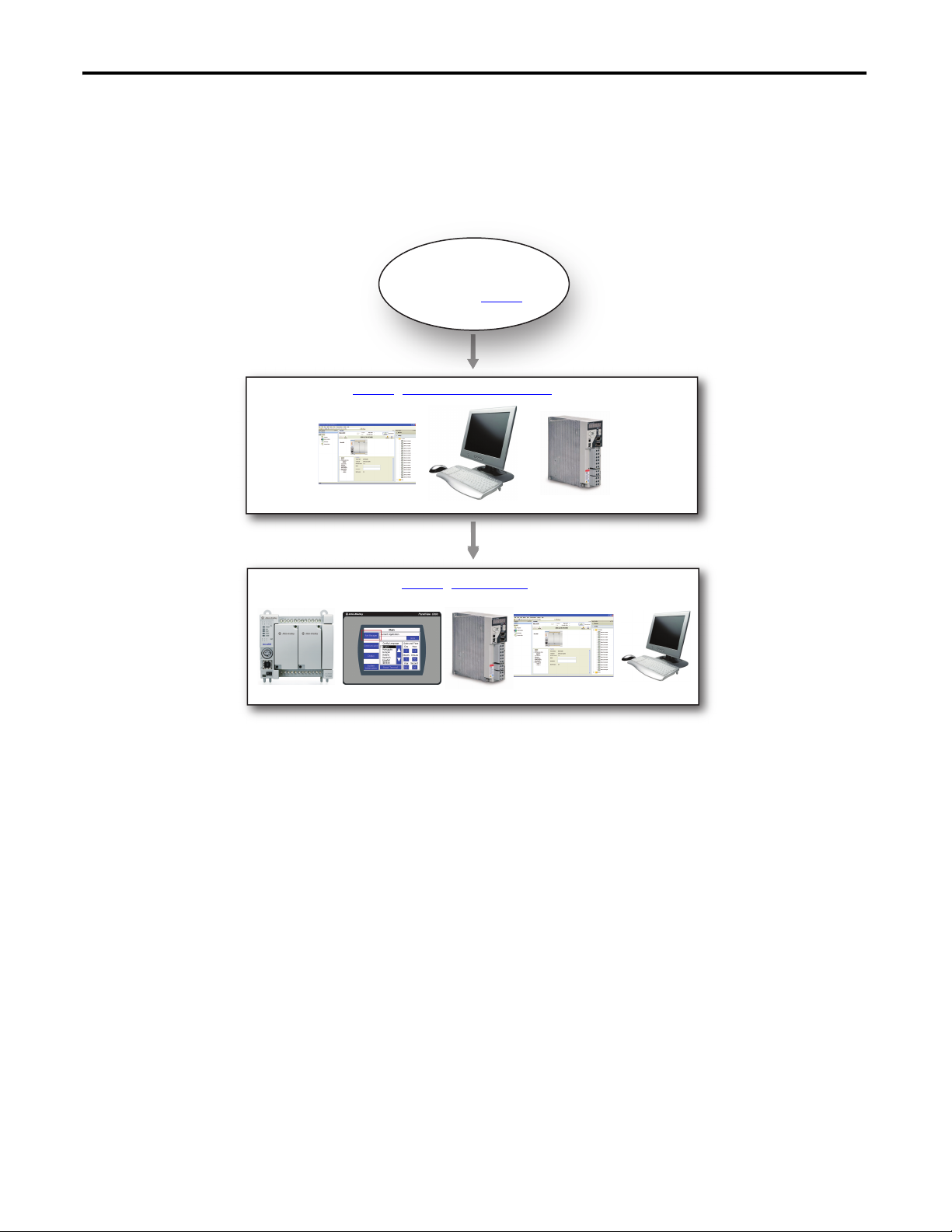
Connected Components Accelerator Toolkit Outline
Follow this path to complete your Connected Components Accelerator Toolkit (CCAT) project.
Chapter 1 - Micro800 Controller PTO Axis Setup
Chapter 2 - System Validation
Getting Started CCAT with System
Design Assistant Quick Start,
publication CC-QS035

4 Rockwell Automation Publication CC-QS033A-EN-P - February 2014
Where to Start
Notes:

Rockwell Automation Publication CC-QS033A-EN-P - February 2014 5
Table of Contents
Preface
About This Publication. . . . . . . . . . . . . . . . . . . . . . . . . . . . . . . . . . . . . . . . . . . . . 7
Terminology. . . . . . . . . . . . . . . . . . . . . . . . . . . . . . . . . . . . . . . . . . . . . . . . . . . . . . . 8
Additional Resources . . . . . . . . . . . . . . . . . . . . . . . . . . . . . . . . . . . . . . . . . . . . . . . 9
Available Connected Components Accelerator Toolkits . . . . . . . . . . . . . . 9
Chapter 1
Micro800 Controller PTO Axis Setup
Before You Begin . . . . . . . . . . . . . . . . . . . . . . . . . . . . . . . . . . . . . . . . . . . . . . . . 11
What You Need . . . . . . . . . . . . . . . . . . . . . . . . . . . . . . . . . . . . . . . . . . . . . . . . . 11
Follow These Steps. . . . . . . . . . . . . . . . . . . . . . . . . . . . . . . . . . . . . . . . . . . . . . . 12
Configure the Kinetix 3 Drive. . . . . . . . . . . . . . . . . . . . . . . . . . . . . . . . . . . . . 13
Configure Your Kinetix 3 Drive and Personal Computer
Connection . . . . . . . . . . . . . . . . . . . . . . . . . . . . . . . . . . . . . . . . . . . . 14
Connect to Your Drive . . . . . . . . . . . . . . . . . . . . . . . . . . . . . . . . . . . . . . . . . . . 18
Configure Your Drive by Using Connected Components
Workbench Software . . . . . . . . . . . . . . . . . . . . . . . . . . . . . . . . . . . 21
Configure the Micro800 Controller . . . . . . . . . . . . . . . . . . . . . . . . . . . . . . . 24
Change to Your Controller Type . . . . . . . . . . . . . . . . . . . . . . . . . . . . . . 24
Configure the PTO Channel. . . . . . . . . . . . . . . . . . . . . . . . . . . . . . . . . . . . . . 26
I/O Assignment. . . . . . . . . . . . . . . . . . . . . . . . . . . . . . . . . . . . . . . . . . . . . . 26
Sensors . . . . . . . . . . . . . . . . . . . . . . . . . . . . . . . . . . . . . . . . . . . . . . . . . . . . . . 27
Configure Drive Communication . . . . . . . . . . . . . . . . . . . . . . . . . . . . . . . . . 28
Configure Communication Attributes . . . . . . . . . . . . . . . . . . . . . . . . . 28
Chapter 2
System Validation
Before You Begin . . . . . . . . . . . . . . . . . . . . . . . . . . . . . . . . . . . . . . . . . . . . . . . . 31
What You Need . . . . . . . . . . . . . . . . . . . . . . . . . . . . . . . . . . . . . . . . . . . . . . . . . 31
Follow These Steps. . . . . . . . . . . . . . . . . . . . . . . . . . . . . . . . . . . . . . . . . . . . . . . 32
System Overview. . . . . . . . . . . . . . . . . . . . . . . . . . . . . . . . . . . . . . . . . . . . . . . . . 33
Configure Your Controller Serial Port . . . . . . . . . . . . . . . . . . . . . . . . . . . . . 34
Configure Input Filter for High Speed Counter . . . . . . . . . . . . . . . . . . . . 36
Configure PanelView Component Terminal Communication
Settings . . . . . . . . . . . . . . . . . . . . . . . . . . . . . . . . . . . . . . . . . . . . . . . . 37
Connect Your Devices. . . . . . . . . . . . . . . . . . . . . . . . . . . . . . . . . . . . . . . . . . . . 39
Download Your Program to the Controller . . . . . . . . . . . . . . . . . . . . . . . . 41
Configure the IP Address for Your PanelView Component
Terminal . . . . . . . . . . . . . . . . . . . . . . . . . . . . . . . . . . . . . . . . . . . . . . . 43
Transfer Your HMI Application to the PanelView Component
Terminal . . . . . . . . . . . . . . . . . . . . . . . . . . . . . . . . . . . . . . . . . . . . . . . 43
Validate Your System. . . . . . . . . . . . . . . . . . . . . . . . . . . . . . . . . . . . . . . . . . . . . 46
Understand the Machine Overview Screen . . . . . . . . . . . . . . . . . . . . . 46
Understand the Machine Functions Screen . . . . . . . . . . . . . . . . . . . . . 46
Explore the Command and Status Screen. . . . . . . . . . . . . . . . . . . . . . . 48
Explore the Axis Configuration Screen . . . . . . . . . . . . . . . . . . . . . . . . . 50
Explore the Kinetix 3 and HSC Configuration Screen . . . . . . . . . . . 51
Explore the Advance Move Screen . . . . . . . . . . . . . . . . . . . . . . . . . . . . . 53

6 Rockwell Automation Publication CC-QS033A-EN-P - February 2014
Table of Contents
Explore the Kinetix 3 Status Screen . . . . . . . . . . . . . . . . . . . . . . . . . . . . 56
Explore the Fault Screen. . . . . . . . . . . . . . . . . . . . . . . . . . . . . . . . . . . . . . . 57
Appendix A
Kinetix 3 Drive Component-class
User-defined Functional Block
PTO Application Building Block User-defined Function Block . . . . . . 59
RA_Motion_Move_Cmd User-defined Function Block . . . . . . . . 59
RA_K3_MBUS_STS User-defined Function Block . . . . . . . . . . . . . . . . . 64
RA_K3_MBUS_STS_Extended User-defined Function Block. . . . . . . 67
Appendix B
Global Variables
. . . . . . . . . . . . . . . . . . . . . . . . . . . . . . . . . . . . . . . . . . . . . . . . . . . . . . . . . . . . . . . . . 71
Appendix C
Motion Axis Setup for PTO Building
Block
I/O assignment . . . . . . . . . . . . . . . . . . . . . . . . . . . . . . . . . . . . . . . . . . . . . . . . . . 73
General. . . . . . . . . . . . . . . . . . . . . . . . . . . . . . . . . . . . . . . . . . . . . . . . . . . . . . . . . . 76
Motor and Load. . . . . . . . . . . . . . . . . . . . . . . . . . . . . . . . . . . . . . . . . . . . . . . . . . 80
Limits . . . . . . . . . . . . . . . . . . . . . . . . . . . . . . . . . . . . . . . . . . . . . . . . . . . . . . . . . . . 81
Dynamics. . . . . . . . . . . . . . . . . . . . . . . . . . . . . . . . . . . . . . . . . . . . . . . . . . . . . . . . 83
Homing . . . . . . . . . . . . . . . . . . . . . . . . . . . . . . . . . . . . . . . . . . . . . . . . . . . . . . . . . 85
Appendix D
Configure a Series A Kinetix 3 Drive
What You Need. . . . . . . . . . . . . . . . . . . . . . . . . . . . . . . . . . . . . . . . . . . . . . . . . . 87
Configure Your Personal Computer and Kinetix 3 Drive
Connection . . . . . . . . . . . . . . . . . . . . . . . . . . . . . . . . . . . . . . . . . . . . 87
Configure Your Drive with Ultraware Software. . . . . . . . . . . . . . . . . . . . . 91
Configure Your Drive for Modbus Communication Protocol . . . . . . . . 93

Rockwell Automation Publication CC-QS033A-EN-P - February 2014 7
Preface
About This Publication
This quick start is designed to provide instructions for implementing a Pulse-Train Output (PTO) motion control of a
Kinetix® 3 component-class drive by using Connected Components Workbench™ software and a Micro800™ programmable
logic controller (PLC).
To assist in the design and installation of your system, application files and other information are provided by the
Connected Components Accelerator Toolkit (CCAT). The CCAT provides bills of materials (BOM), CAD drawings for
panel layout and wiring, control programs, Human-machine interface (HMI) screens, and more. With these tools and the
built-in best-practices design, the system designer is free to focus on the design of their machine control and not on design
overhead tasks.
The CCAT is available on the Connected Components Accelerator Toolkit DVD, publication CC-QR002, or through
the Rockwell Software Download and Registration System (SDRS) at
http://www.rockwellautomation.com/
rockwellautomation/products-technologies/connected-components/tools/accelerator-toolkit.page.
The beginning of each chapter contains the following information. Read these sections carefully before beginning work in
each chapter:
• Before You Begin - This section lists the steps that must be completed and decisions that must be made before
starting that chapter. The chapters in this quick start do not have to be completed in the order in that they appear,
but this section defines the minimum amount of preparation required before completing the current chapter.
• What You Need - This section lists the tools that are required to complete the steps in the current chapter. This
includes, but is not limited to, hardware and software.
• Follow These Steps - This section illustrates the steps in the current chapter and identifies the steps that are required
to complete the examples.

8 Rockwell Automation Publication CC-QS033A-EN-P - February 2014
Preface
Terminology
Term (abbreviation) Definition
Application Sequence Programs User-modified programs that work together with the standard state machine logic to
control what the machine does while in the abort, clear, reset, run and stop states.
Auto/manual Operation When the PanelView™ Component terminal is in Auto mode, the controller logic controls
the machine and monitors machine status.
When the PanelView Component terminal switches to Manual mode, the terminal takes
over control. Command buttons and numeric entry fields are available only when the
machine is in Manual mode.
Bill of Materials (BOM) A list of components needed for your system.
Building Block (BB) Tools for accelerating and simplifying the development of a Micro800 controller-based
application. A typical building block includes a starting Bill of Material (BOM), Computer-
Aided Design (CAD) drawings, Micro800 controller programs, PanelView Component
terminal applications, and a quick star t document.
Computer-Aided Design (CAD) A computer-based system developed to facilitate design of mechanical parts.
Connected Comp onents Accelerator Toolkit (CCAT) Software with application files and other information to speed the design and star tup of
component-based machines.
Connected Components Workbench Software environment for configuring or programming Micro800 controllers, PanelView
Component terminals, Kinetix 3 drives, and other component-level products.
Connected Components Workbench Project A project consists of one or more of the following:
• Micro800 controller configuration
• Up to 256 Micro800 controller programs, each with program local variables
• Micro800 controller global variables
• PanelView Component terminal application
• Kinetix 3 drive parameter lists
Global Variables Project variables that can be accessed by any program, including all I/O and system
variab les.
State Machine Control Code Machine logic for coordinating overall machine operation based on states. The state
machine broadcasts commands and receives feedback information from each of the
building blocks via user-modified application sequence programs.
Tag s A PanelView Component term for variables.
User-defined Function Blocks (UDFBs) Function block instructions that can be used like standard function block instruc tions
within any Connected Components Workbench programming language. These can be
written by anyone using Connected Components Workbench software. Many UDFBs are
posted on the Rockwell Automation sample code website: http://
samplecode.rockwellautomation.com/idc/groups/public/documents/webassets/
sc_home_page.hcst.
User-defined Object (UDO) A collection of PanelView Component terminal screen objects that can be pasted into a
new screen.

Rockwell Automation Publication CC-QS033A-EN-P - February 2014 9
Preface
Additional Resources
These documents contain additional information concerning related products from Rockwell Automation.
You can view or download publications at http://www.rockwellautomation.com/literature. To order paper copies of
technical documentation, contact your local Allen-Bradley distributor or Rockwell Automation sales representative.
Available Connected Components Accelerator Toolkits
For the most up-to-date listing of available Connected Components Accelerator Toolkits and related quick starts, refer to
these resources:
• Rockwell Automation Connected Components Accelerator Toolkit website at http://
www.rockwellautomation.com/rockwellautomation/products-technologies/connected-components/tools/
accelerator-toolkit.page
• Connected Components Accelerator Toolkit Building Block Project Descriptions Quick Reference, publication
CC-QR003
Resource Description
Connected Components Accelerator Toolkit DVD,
publication CC-QR002
Provides files for the Connected Component Accelerator Toolkits.
Micro800 and Connected Components Workbench Getting
Started Guide, publication 2080-QR001
Provides information on basic Micro800 controller and Connected Components Workbench software functions.
Micro800 and Connected Components Workbench Application
Guide, publication 2080-QR002
Provides procedures for completing basic tasks in Connected Components Workbench software and for using
Connected Components Workbench software with component-class products.
Micro800 Programmable Controller External AC Power Supply
Installation Instructions, publication 2080-IN001
Provides information on mounting and wiring the optional external power supply.
Micro800 Plug-in Modules User Manual,
publication 2080-UM004
Provides information on installing Micro800 plug-in modules and accessories including wiring and
troubleshooting.
Micro820 Programmable Controllers User Manual,
publication 2080-UM005
Provides information on installing Micro820 controllers including wiring and troubleshooting.
Micro830™ Programmable Controllers User Manual, publication
2080-UM002
Provides information on installing the Micro830 Programmable Controller including wiring and troubleshooting.
PanelView Component Installation Instructions, publication
2711C-IN001
Provides information on installing the PanelView Component HMI terminals including wiring, grounding, and
troubleshooting.
PanelView Component Operator Terminals User Manual,
publication 2711C-UM001
Provides information about using PanelView Component HMI terminals.
Kinetix 3 Component Servo Drives User Manual, publication 2071-
UM001
Provides a reference guide for Kinetix 3 drive systems, and accessories. It also contains procedures on how to
install, wire, and troubleshoot your drive.
Kinetix 3 Host Commands for Serial Communication Reference
Manual, publication 2071-RM001
Provides information on the serial communication commands, both ASCII and ModBus-RTU, for interfacing a
motion controller with the Kinetix 3 drive.
Kinetix 3 Component Servo Drives Installation Instruction,
publication 2071-IN001
Provides information on installing your Kinetix 3 drive system.

10 Rockwell Automation Publication CC-QS033A-EN-P - February 2014
Preface
Notes:Notes:

Rockwell Automation Publication CC-QS033A-EN-P - February 2014 11
Chapter 1
Micro800 Controller PTO Axis Setup
In this chapter, you configure a Pulse-Train-Output channel in a Micro800 controller to control a Kinetix 3 drive. You set
up the Modbus RTU communication for the controller to monitor drive status.
Before You Begin
Review the Getting Started CCAT with System Design Assistant Quick Start, publication CC-QS035.
What You Need
Kinetix 3 Drive Setup:
• Personal computer with an available USB port
• Connected Components Workbench software, version 6 or later
• RSLinx® Classic software
• 1203-USB converter
• 2090-CCMUSDS-48AAxx Communication cable
• Kinetix 3 drive Series B or later; firmware revision 3.005 or later
Micro800 Controller Setup:
• Personal computer with an available USB port
• Connected Components Workbench software, version 6 or later
• USB printer cable (A to B) for personal computer to Micro800 controller communication
• Micro830 or Micro850 controller with transistor output
12 Rockwell Automation Publication CC-QS033A-EN-P - February 2014
Chapter 1 Micro800 Controller PTO Axis Setup
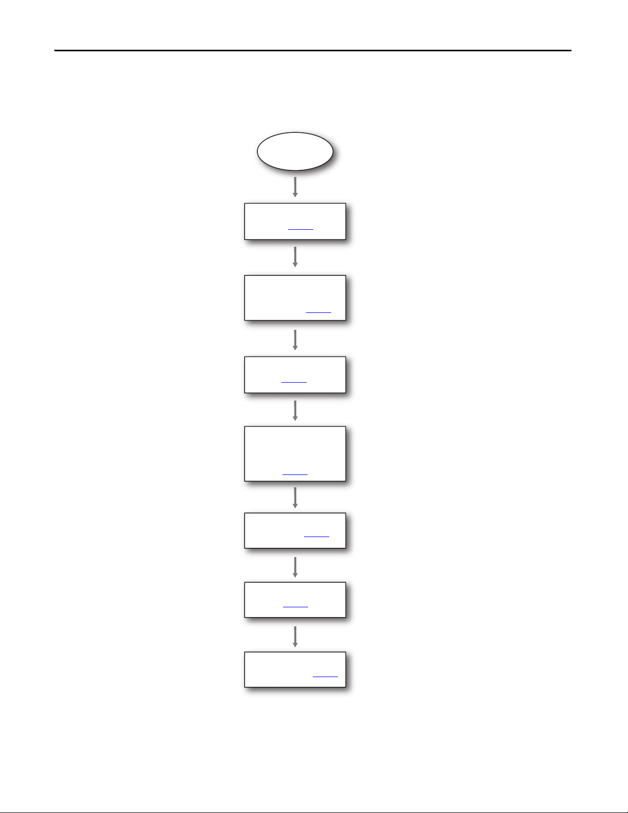
Follow These Steps
Follow these steps to configure your Micro800 Controller and Kinetix 3 drive for PTO.
Start
Configure the Kinetix 3 Drive
on page 13
Configure Your Kinetix 3 Drive
and Personal Computer
Connection on page 14
Connect to Your Drive on
page 18
Configure Your Drive by Using
Connected Components
Workbench Software on
page 21
Configure the Micro800
Controller on page 24
Configure the PTO Channel on
page 26
Configure Drive
Communication on page 28

Rockwell Automation Publication CC-QS033A-EN-P - February 2014 13
Micro800 Controller PTO Axis Setup Chapter 1
Configure the Kinetix 3 Drive
In this section, you configure your personal computer and Series B Kinetix 3 drive with firmware revision 3.005 by using
Connected Components Workbench version
6 or later software. You can find the hardware series identifier on the label
attached to the side of the product.
See Figure 1 and Figure 2 to identify the Series of your Kinetix 3 drive.
Figure 1 - Label of Series B Kinetix 3 Drive - That Is Supported by Connected Components Workbench Version 6 or Later
Figure 2 - Label of a Series A Kinetix 3 Drive - That Is Supported by Ultraware Software Only
To configure a Series A Kinetix 3 drive, refer to Configure a Series A Kinetix 3 Drive in Appendix D.
BULLETIN 2071 Kinetix 3 Component Servo Drive, 400W
CAT. NO. 2071-AP1 SERIES B PN-185999
MAX SHORT CIRCUIT 1000,000A
INSTRUCTION MANUAL 2071-IN001x-EN-P FIRMWARE VER. V03.01
BULLETIN 2071 Kinetix 3 Component Servo Drive, 1.1A
CAT. NO. 2071-AP1 SERIES A
MAX SHORT CIRCUIT 1000,000A
INSTRUCTION MANUAL 2071-IN001x-EN-P FIRMWARE VER. V02.00

14 Rockwell Automation Publication CC-QS033A-EN-P - February 2014
Chapter 1 Micro800 Controller PTO Axis Setup
Configure Your Kinetix 3 Drive and Personal Computer Connection
Follow these steps to configure the connection between your personal computer and your drive.
1. Verify your Kinetix 3 drive is Series B with firmware revision 3.005 or later.
Refer to page 13 for examples.
2. Use the keypad on the front of the drive to set the following parameters.
3. Connect the Kinetix 3 drive to your personal computer by using cables shown here.
If you are prompted to install drivers, use the recommended drivers.
4. Verify the COM port number of the 1203-USB adapter in Device Manager on your computer, from the Start menu,
choose Run.
The Run dialog box appears.
5. Type devmgmt.msc in the Open field.
Parameter Name Parameter Setting
Drive Address Pr0.07 248
Serial Port Configuration Pr0.09 1102
where, 2 - 19,200 Kbps Baud Rate
0 - 8 Data Bits, No Parity, 1 Stop Bit
1 - Modbus-RTU protocol
1 - RS-485
Item Description
1 Kinetix 3 drive
2 1203-USB converter cable, catalog number 2090-CCMUSDS-48AAxx
3 1203-USB converter
4 USB cable
5 Personal computer with Connected Components Workbench software
5
2
1
3
4
Rockwell Automation Publication CC-QS033A-EN-P - February 2014 15
Micro800 Controller PTO Axis Setup Chapter 1
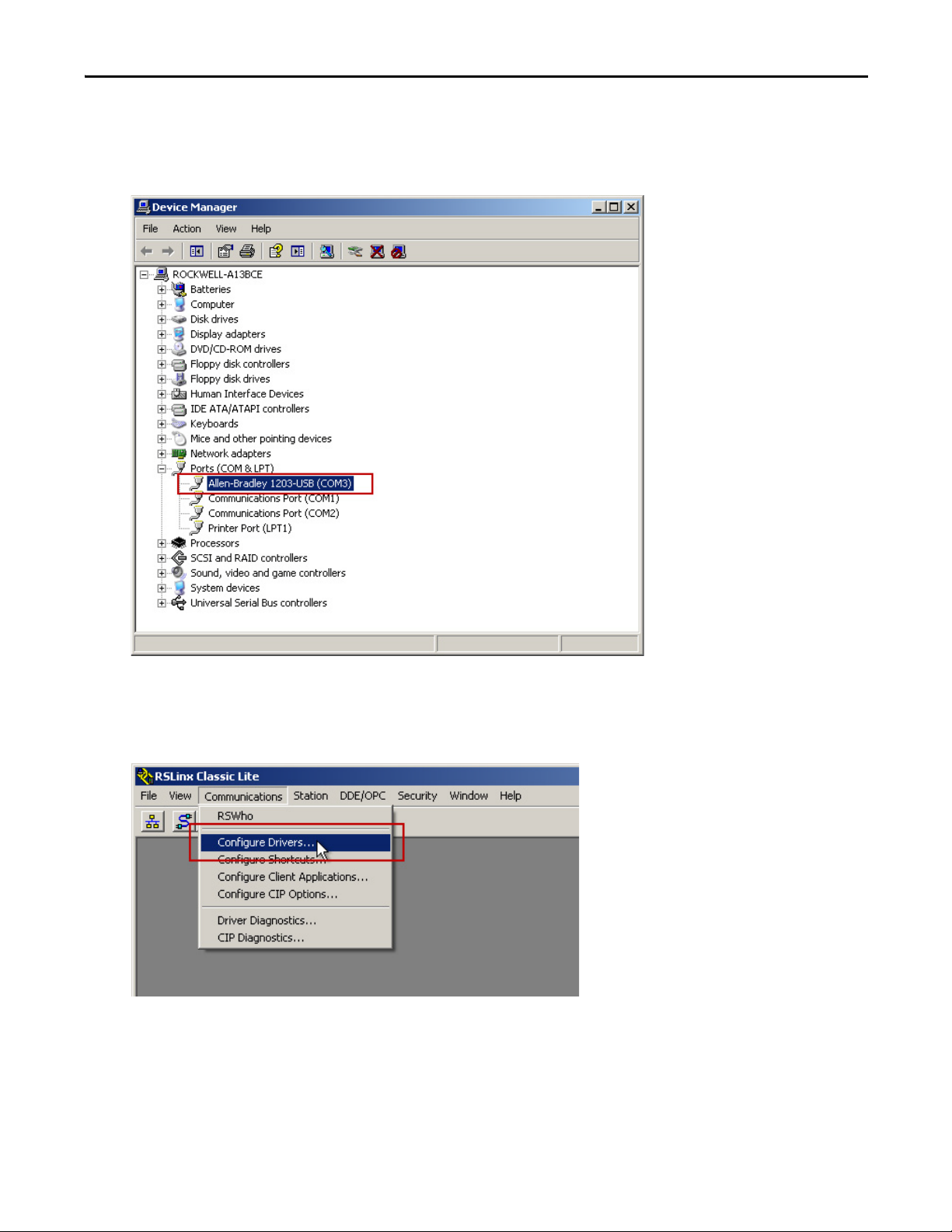
6. Expand the Ports (COM & LPT) group, and locate the Allen-Bradley® 1203-USB device.
The COM port is specified in parenthesis next to the device name, COM3 in this example. It can be different on
your computer.
7. Note your COM port name and close the Device Manager window.
8. To configure an RS-232 DF1 driver, start RSLinx® Classic software.
9. From the Communication menu, choose Configure Drivers.
16 Rockwell Automation Publication CC-QS033A-EN-P - February 2014
Chapter 1 Micro800 Controller PTO Axis Setup
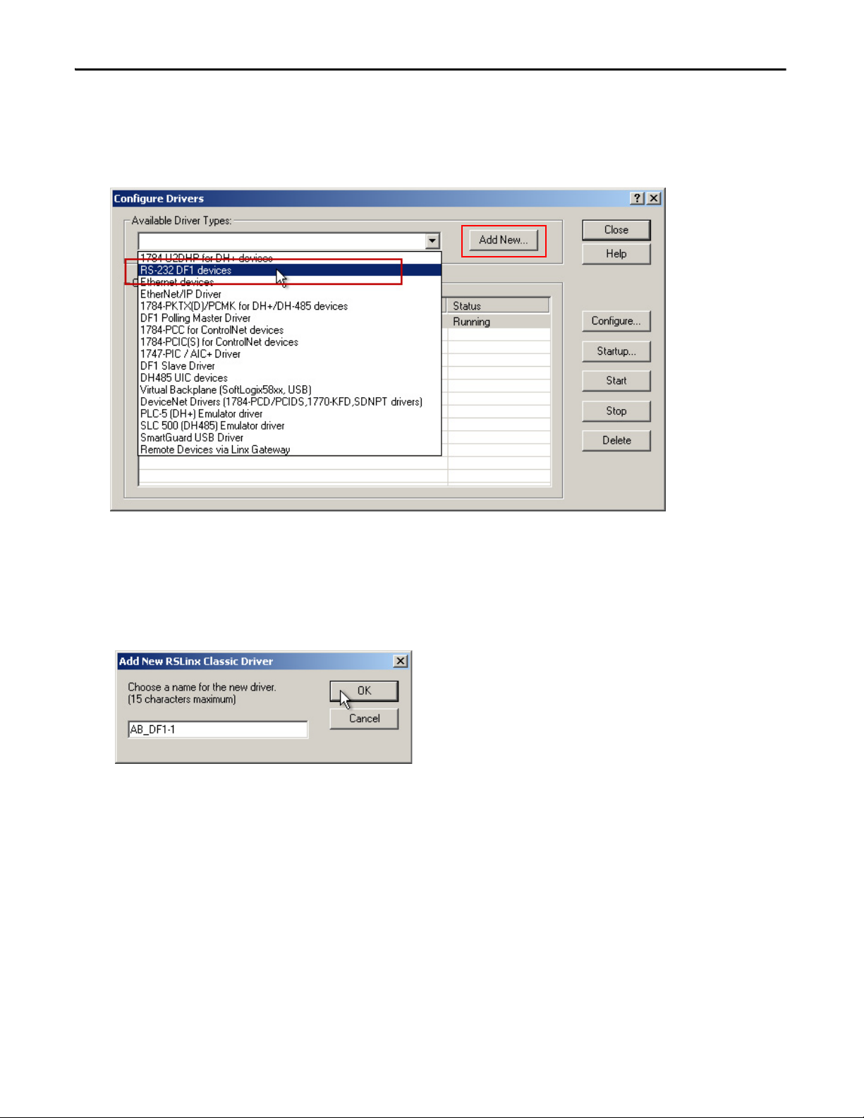
The Configure Drivers dialog box appears.
10. From the Available Driver Types pull-down menu, choose RS-232 DF1 devices.
11. Click Add New.
The Add New RSLinx Classic Driver dialog box appears.
12. Type a name for your driver,
You can use the default name, if desired.
13. Click OK.
Rockwell Automation Publication CC-QS033A-EN-P - February 2014 17
Micro800 Controller PTO Axis Setup Chapter 1
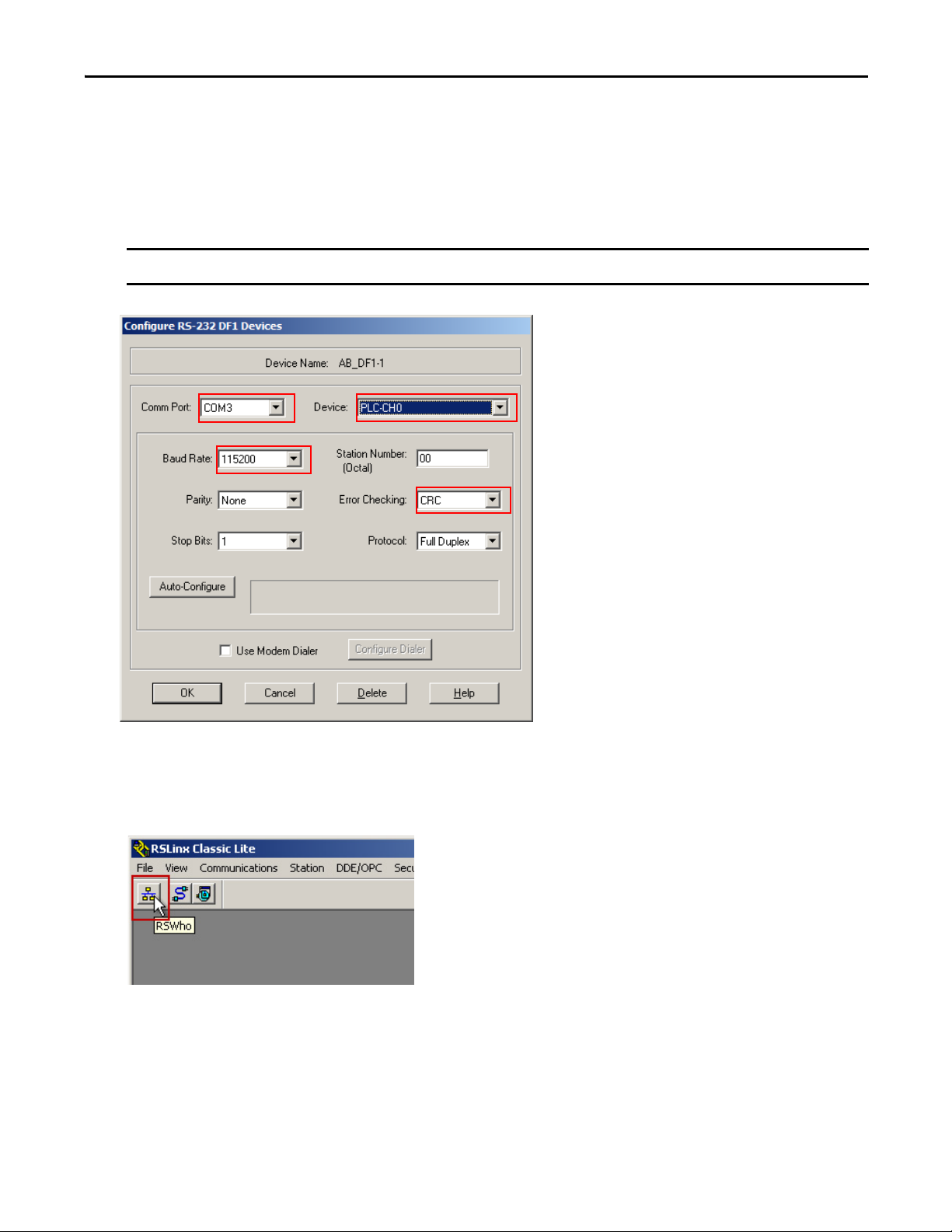
14. Configure the driver settings.
a. From the Comm Port pull-down menu, choose the port number of your 1203-USB serial adapter.
b. From the Device pull-down menu, choose PLC-CH0.
c. From the Baud Rate pull-down menu, choose 115200 baud rate.
d. From the Error Checking pull-down menu, choose CRC.
15. Click OK.
16. In the RSLinx tool bar, click the RSWho icon to verify that your drive is properly communicating with RSLinx
Classic software.
IMPORTANT
Do not click auto-configure.
a
b
c
d
18 Rockwell Automation Publication CC-QS033A-EN-P - February 2014
Chapter 1 Micro800 Controller PTO Axis Setup
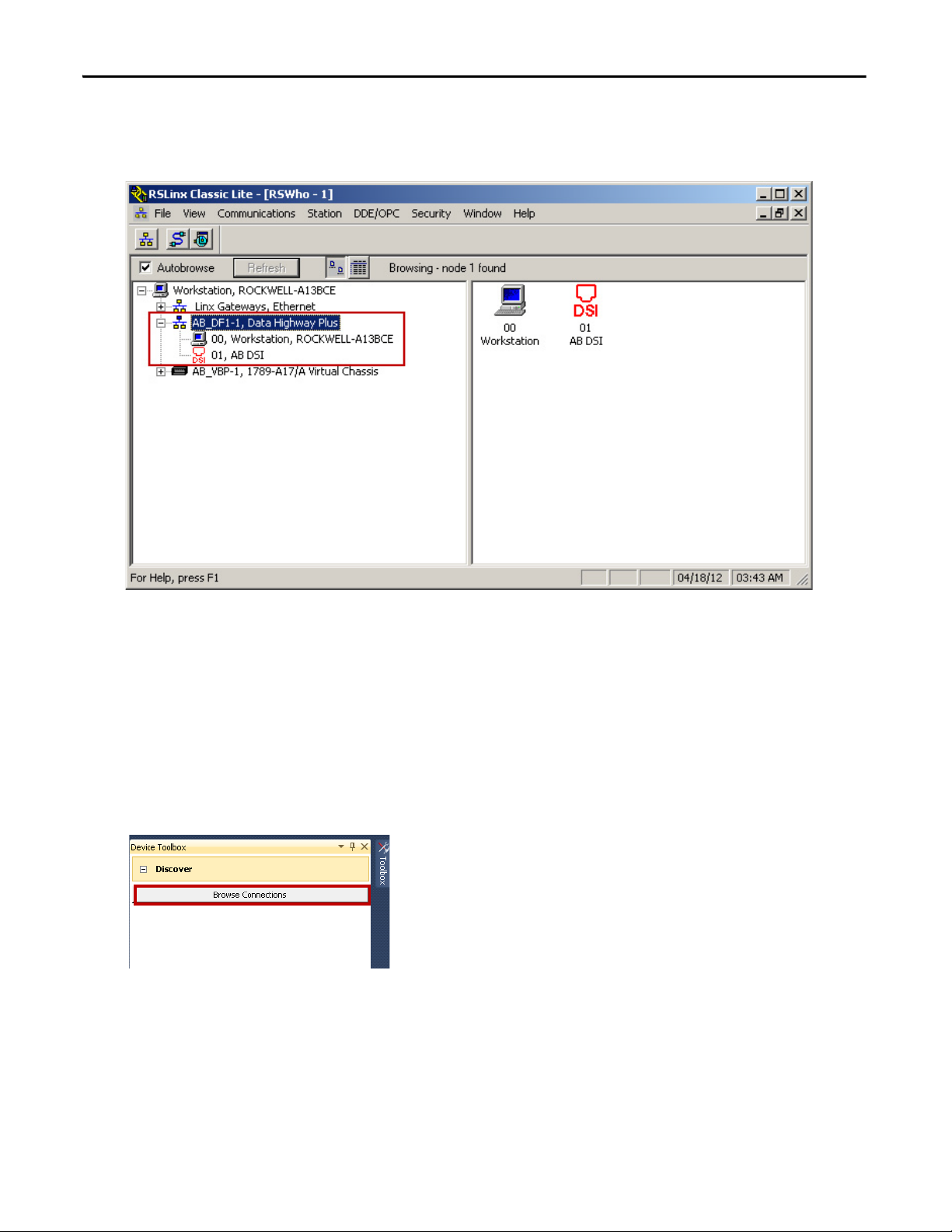
17. Expand your RS-232 DF1 driver, and verify that your drive is displayed.
It is listed as 01, AB DSI. If the drive is not displayed below the driver, check your COM port and driver settings.
18. Close RSLinx Classic software.
Connect to Your Drive
Follow these steps to connect to the Kinetix 3 drive. The Kinetix 3 drive must be Series B or later with firmware revision
3.005 or later.
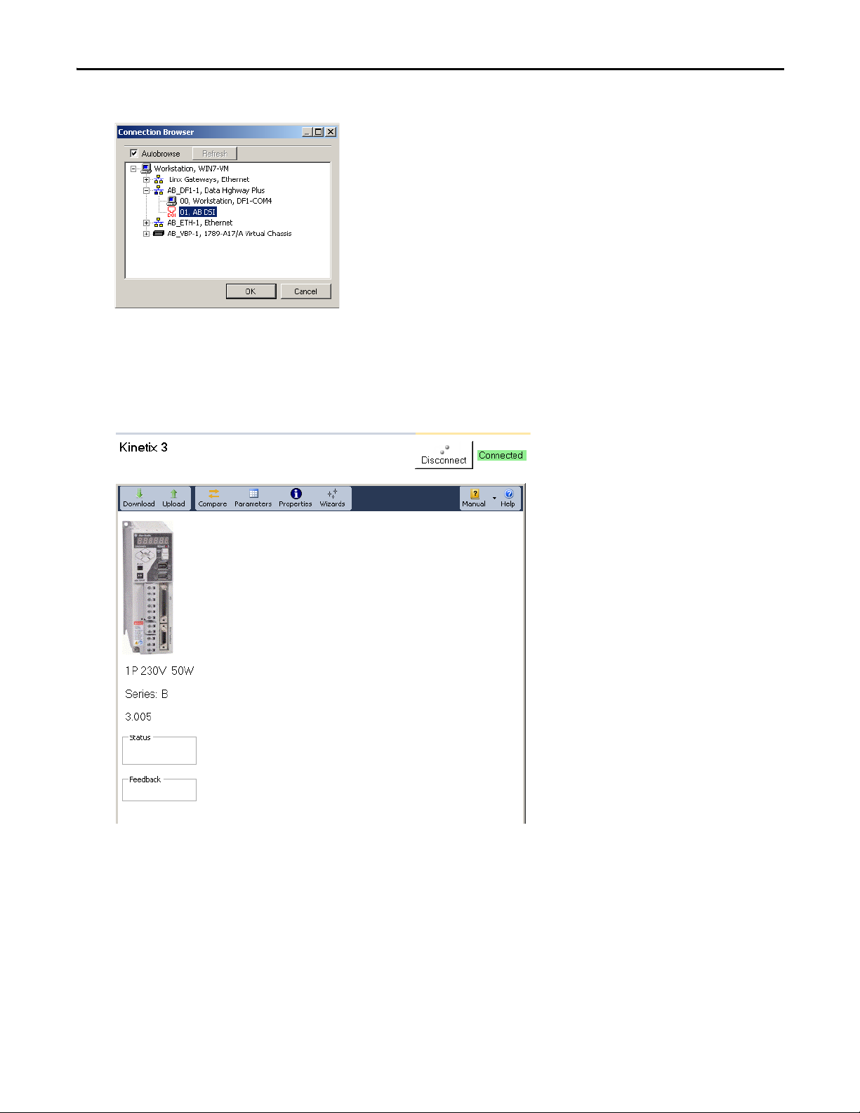
1. From the Connected Components Workbench Device Toolbox, expand Discover, and click Browse Connections.
The Connection Browser dialog box appears.
Rockwell Automation Publication CC-QS033A-EN-P - February 2014 19
Micro800 Controller PTO Axis Setup Chapter 1
2. From the Connection Browser, under AB_DF1-1, select your drive (01, AB DSI) and click OK.
A drive is added to the Project Organizer and the drive's Device Details window appears in the main project
workspace.
3. Follow these step to reset the drive to default settings.
This provides consistent drive settings.
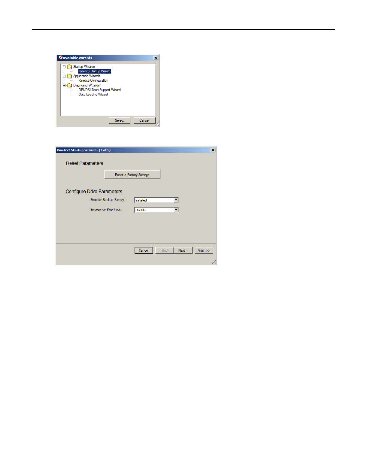
a. From the Toolbar, click the Wizard icon.
TIP
First time uploads take longer.
20 Rockwell Automation Publication CC-QS033A-EN-P - February 2014
Chapter 1 Micro800 Controller PTO Axis Setup
b. Select Kinetic 3 Startup Wizard and click Select.
c. Click Reset to Factory Settings.
The drive is resets.
d. Click Finish.
Rockwell Automation Publication CC-QS033A-EN-P - February 2014 21
Micro800 Controller PTO Axis Setup Chapter 1
Configure Your Drive by Using Connected Components Workbench Software
Follow these steps to configure your drive parameters for the PTO building block.
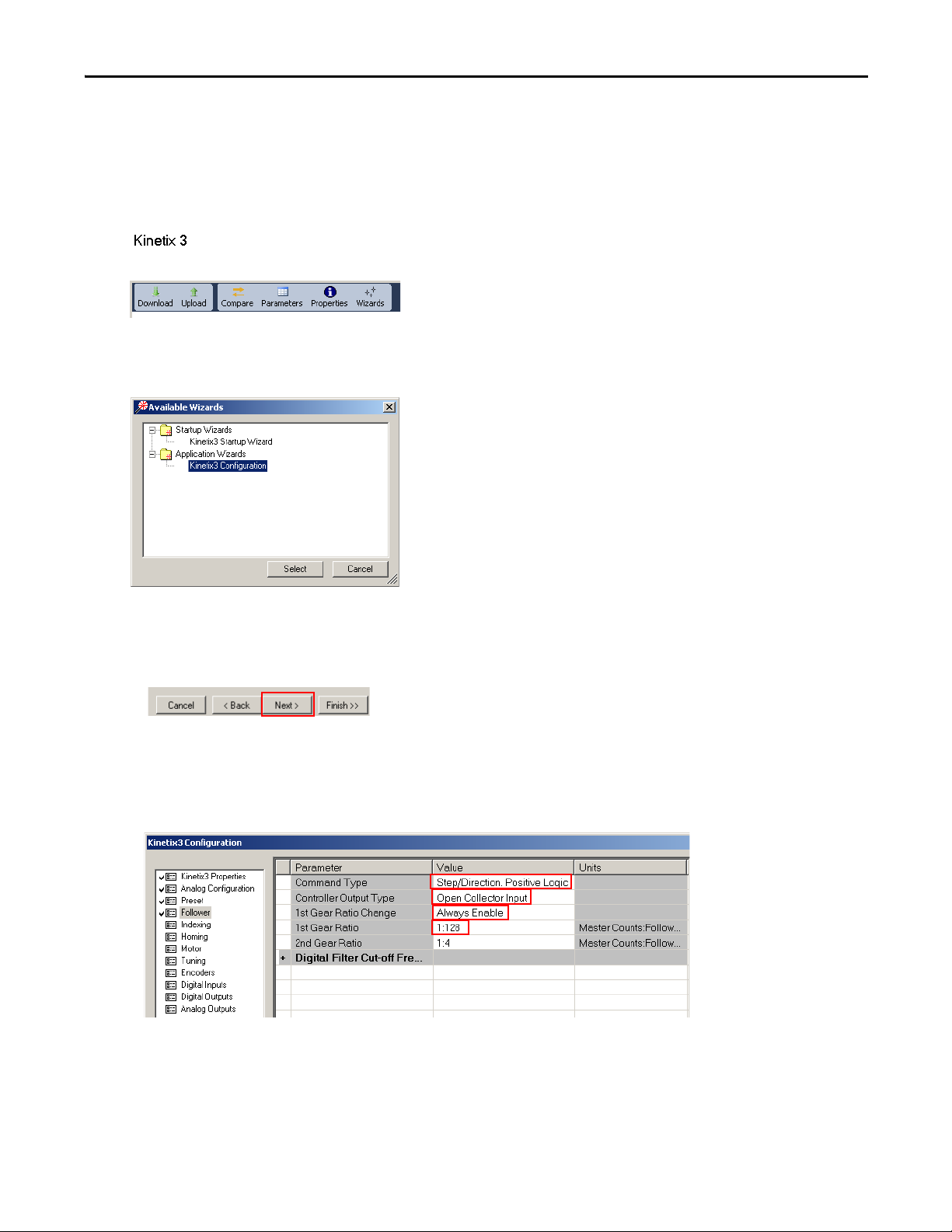
1. From the Tool bar, click the Wizard icon.
The Available Wizards dialog box appears.
2. From the list, select the Kinetix 3 Configuration wizard and click Select.
The application window appears.
3. Follow these steps to configure the Follower mode.
a. Click Next until Follower is highlighted.
b. From the Set Command Type pull-down menu, choose Step/Direction, Positive Logic.
c. From the Controller Output Type pull-down menu, choose Open Collector Input.
d. From the 1st Gear Ratio Change pull-down menu, choose Always Enable.
e. Type 1:128 for 1st Gear Ratio.
b
c
d
e
22 Rockwell Automation Publication CC-QS033A-EN-P - February 2014
Chapter 1 Micro800 Controller PTO Axis Setup
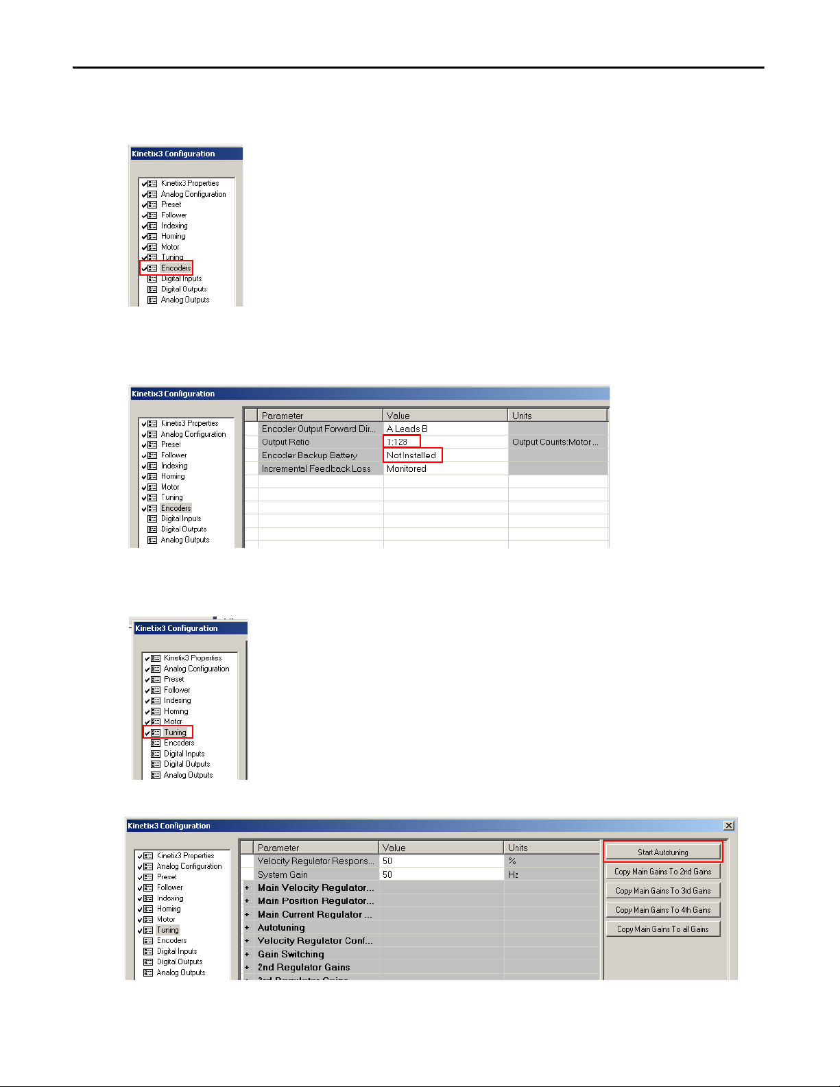
4. Follow these steps to configure the encoder.
a. Click Next to highlight Encoder.
b. Type 1:128 for the Output Ratio.
c. From the Encoder Backup Battery pull-down menu, choose Not Installed.
5. Follow these steps to auto tune your motor.
a. Choose Tuning.
b. From the right pane, click Start Autotuning.
b
c

Rockwell Automation Publication CC-QS033A-EN-P - February 2014 23
Micro800 Controller PTO Axis Setup Chapter 1
6. Follow these steps to configure the Digital Inputs.
a. Click Next to highlight Digital Inputs.
b. From Input 2 pull-down menu, choose Fault Reset.
7. Follow these steps to configure the Digital Outputs.
a. Click Next to highlight Digital Outputs.
b. From Output 1 pull-down menu, choose Ready.
8. Click Next.
9. Click Finish.
10. Save the project.
11. Click the Disconnect icon.
12. Upload the online values to project file.
13. Change the Drive Address (Pr0.07) to 1 by using the keypad interface.
24 Rockwell Automation Publication CC-QS033A-EN-P - February 2014
Chapter 1 Micro800 Controller PTO Axis Setup
Configure the Micro800 Controller
In this section you generate or get a Connected Components Workbench project with servo drive for a PTO application.
You do this by using the CCAT generation function or download the starting project Starting_PTO_r6 from sample code.
To get a starting project go to the website:
http://search.rockwellautomation.com/
search?site=sample_code&client=samplecode&output=xml_no_dtd&proxystylesheet=samplecode.
Change to Your Controller Type
If the starting project does not use your controller, this section shows you how to change it. In this Quick Start, we use
Micro800 controller catalog number 2080-LC50-24QBB.
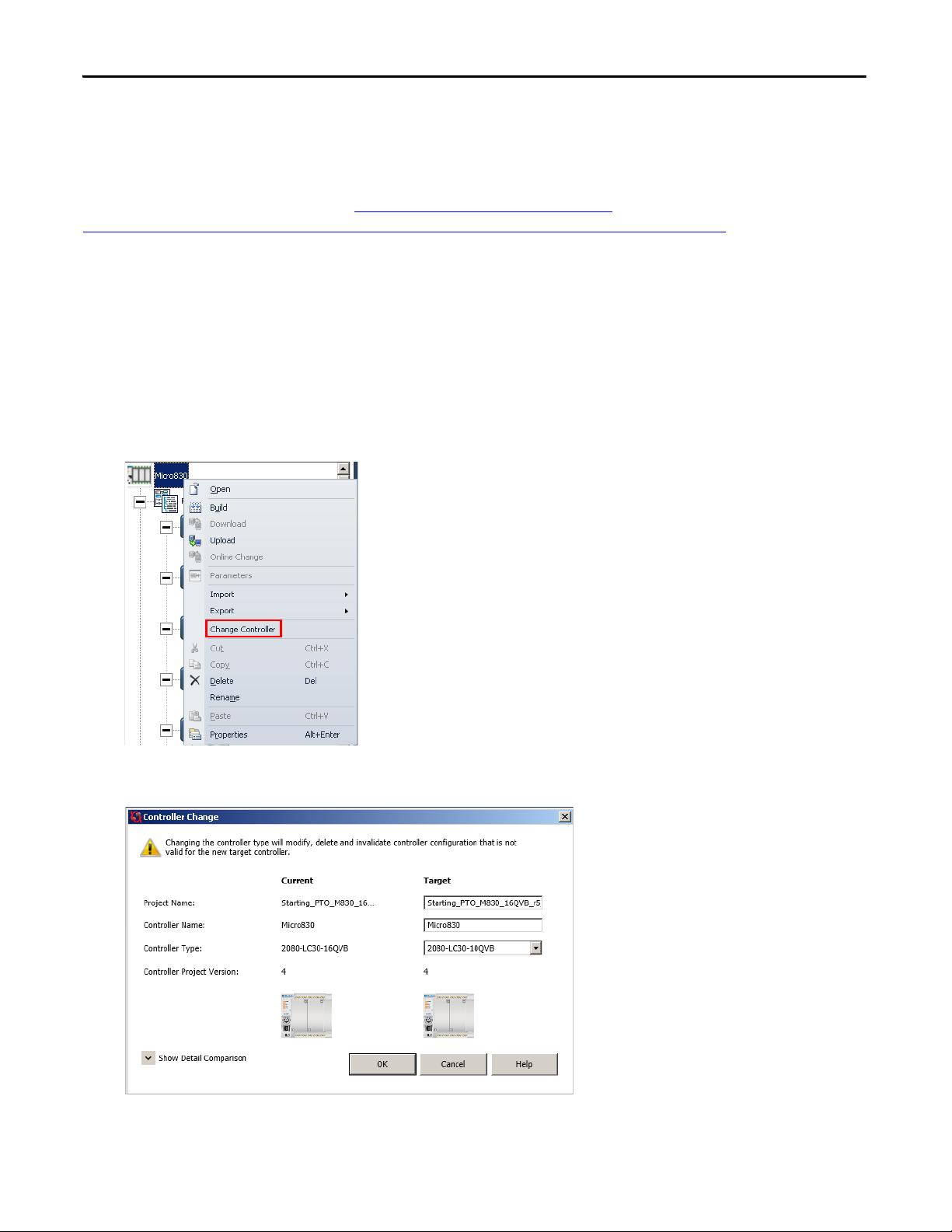
Follow these steps to change the controller.
1. Right-click the Micro830 and choose Change Controller.
The Controller Change dialog box appears.
Rockwell Automation Publication CC-QS033A-EN-P - February 2014 25
Micro800 Controller PTO Axis Setup Chapter 1
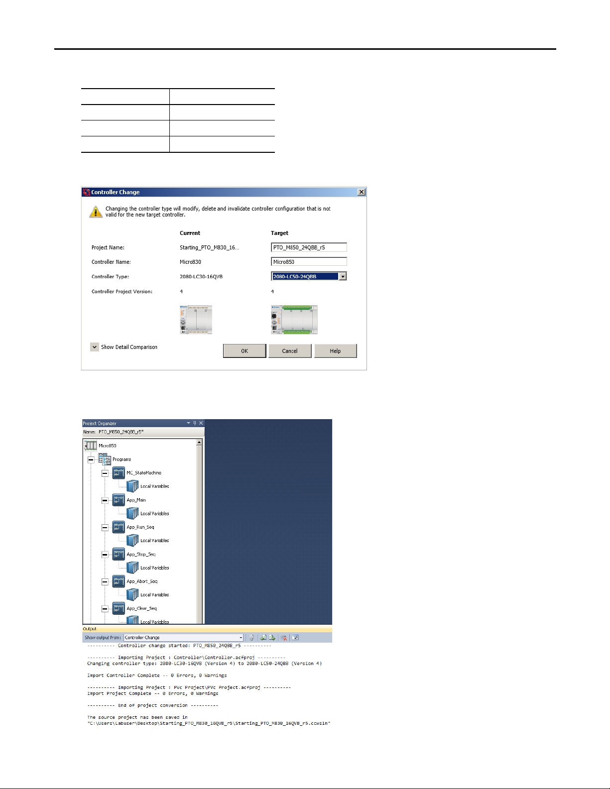
2. From the Controller Change dialog box, type and use the pull-down menu to set the following attributes.
3. Click OK.
A new project named, PTO_M850_24QBB_r5, is created in your My Document > CCW folder and the output
dialog box reports that the controller change is successful.
Attribute Setting
Project Name PTO_M850_24QBB_r5
Controller Name Micro850
Controller type 2080-LC50-24QBB
26 Rockwell Automation Publication CC-QS033A-EN-P - February 2014
Chapter 1 Micro800 Controller PTO Axis Setup
Configure the PTO Channel
The starting project from sample code website is configured to work with the Kinetix 3 drive and wiring diagram. The
default configuration includes a PTO axis. You can find out more about the configuration in
Micro800 Controller PTO
Axis Setup in Appendix C.
For project that is generated with the CCAT generation function the PTO is not configured. You must configure it
manually by using
Appendix C as a reference.
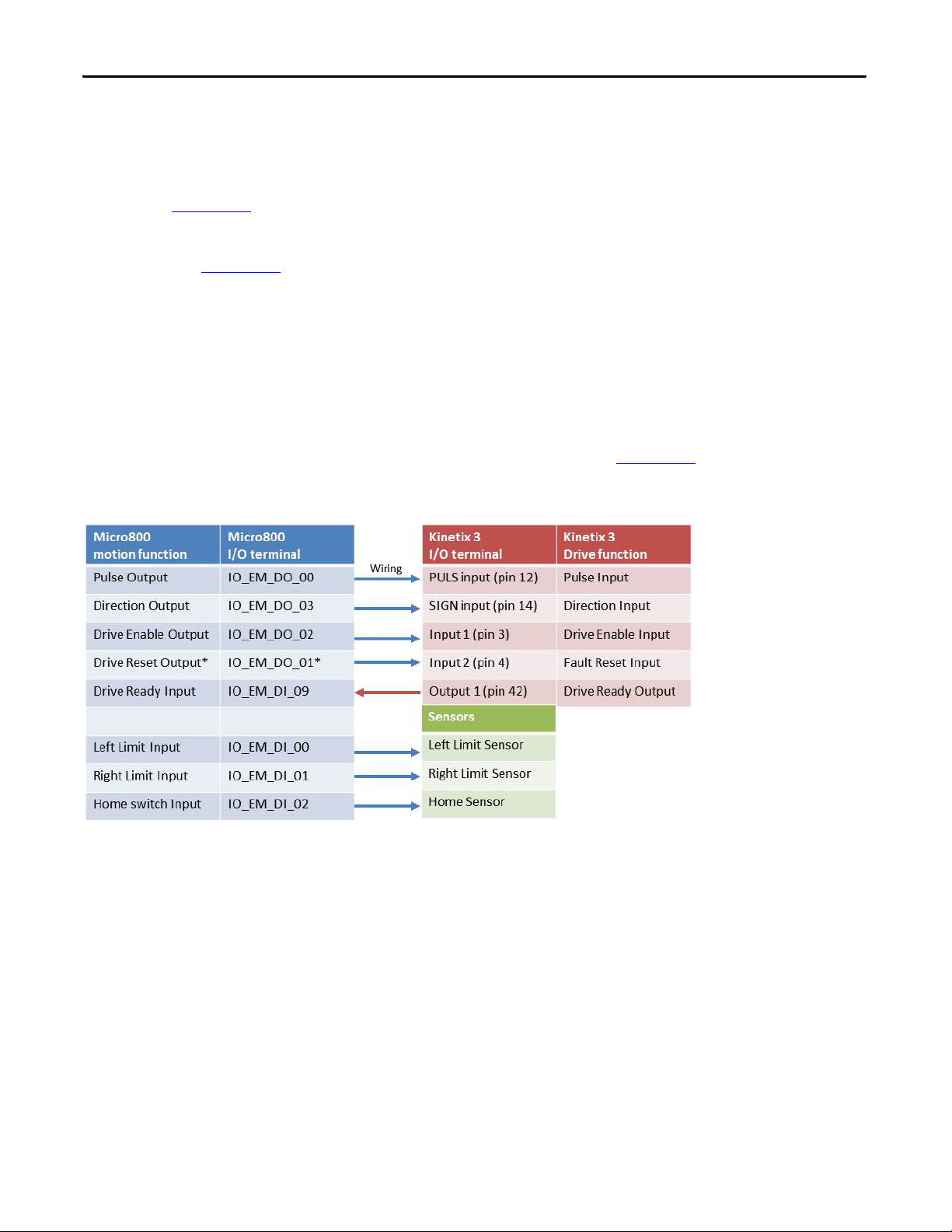
I/O Assignment
Each PTO channel has its own fixed and default I/O assignments for its motion functions. For example, PTO channel 0
uses embedded output 0 and 3 for pulse and direction signal and PTO channel 1 uses embedded output 1 and 4. If you
make any changes to the I/O assignment from the original project, also make the changes to corresponding hard-wiring.
The diagram below shows the I/O assignment for a single PTO application, downloaded from sample code website, a more
detail list of I/O assignments for double and triple PTO applications is provided in
Appendix C.
Figure 3 - I/O Assignment for a Single PTO Application
Rockwell Automation Publication CC-QS033A-EN-P - February 2014 27
Micro800 Controller PTO Axis Setup Chapter 1
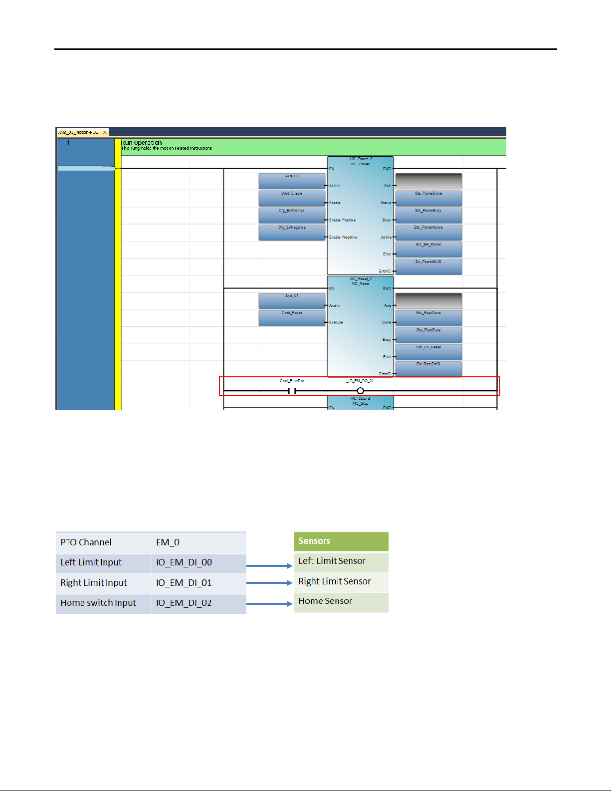
The output terminal for Drive Reset Output must be properly assigned in each ladder program. The output terminal is on
the third branch of rung
one each <User-defined prefix>_Motion ladder diagram.
Figure 4 - Output Terminal for Drive Reset Output Assignment
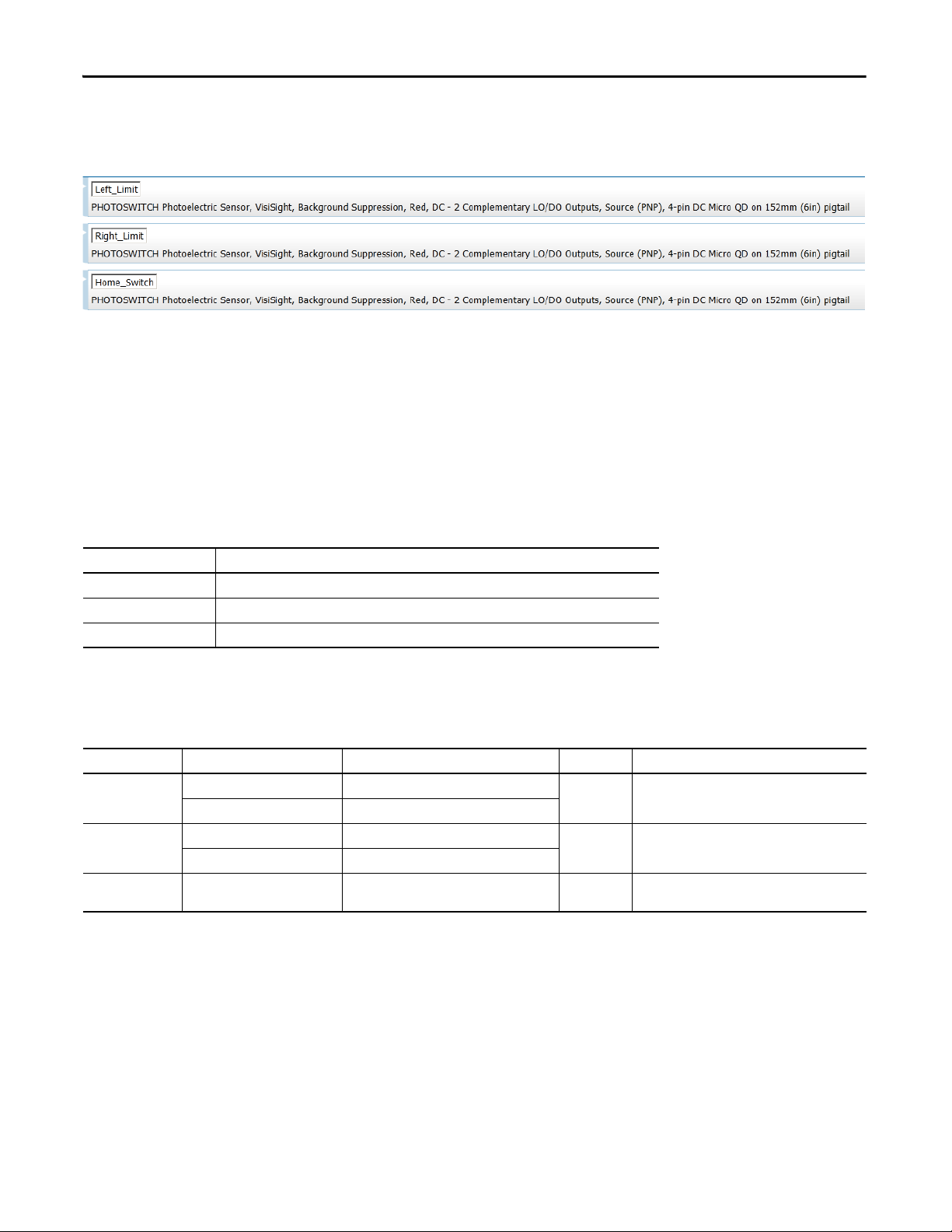
Sensors
In the I/O assignment diagram above, there is a section for sensor connections. The sensors are connected to dedicated
input terminals corresponding to the PTO channel selected.
Figure 5 - Sensor Connections
When you add a PTO application using the CCAT System Design Assistant (SDA), you must add three sensors for each
one. Identify the sensors and enter them in the Sensor section of the System Design Assistant.
28 Rockwell Automation Publication CC-QS033A-EN-P - February 2014
Chapter 1 Micro800 Controller PTO Axis Setup
Here's an example of photoelectric type sensor selected and added in the Sensor section of SDA.
Figure 6 - Example Of Photoelectric Sensor Type
Configure Drive Communication
There is no default communication configuration in the starting project file. You must enter the attributes for the drive-
status communication you want to monitor.
Enter the attributes for the following variables.
Table 1 - Communication Variables
The example in the table below uses the name [Axis_01] for the PTO motion building block, communicating through the
SERIALISOL plug-in module in slot 1, at a refresh rate of 100 ms interval.
Table 2 - Communication Variables Example
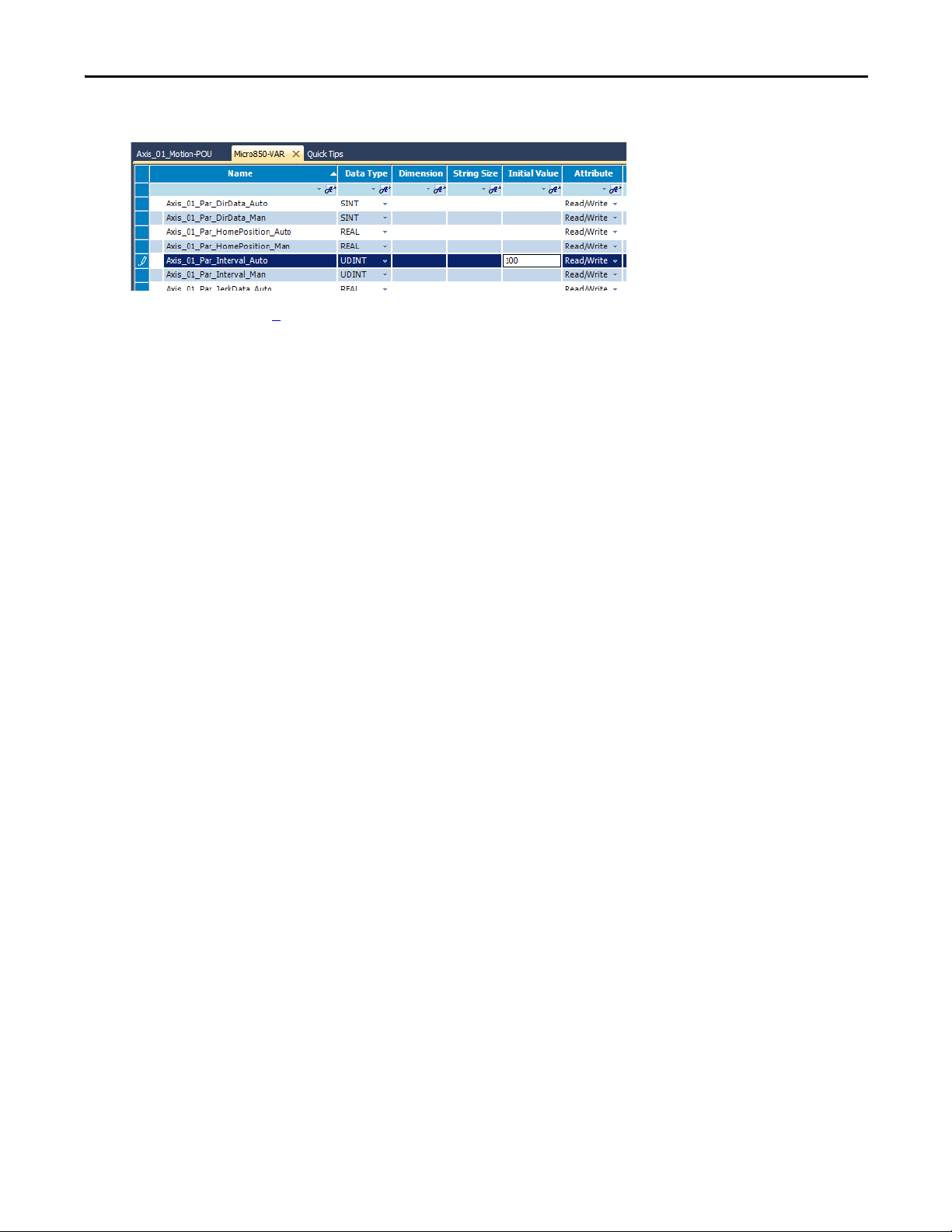
Configure Communication Attributes
Follow these steps to configure the commutation attributes.
1. From the starting project or the project generated by the CCAT generation function, double-click Global Variables.
2. Scroll to find and select the global variable names that require updating.
Attribute Description
Channel Number This is the location of the SERIALISOL plug-in module on the Micro800 controller plug-in slot.
Node Address This is drive address.
Interval This is the refresh rate of the drive status in milliseconds.
Attribute Global Variable Name Description Initial Value Description
Channel Number Axis_01_Cfg_Channel_Man Channel number in Manual mode control. 5 This indicates that the SERIALISOL plug-in module is
in plug-in slot 1.
Axis_01_Cfg_Channel_Auto Channel number in Auto mode.
Node Address Axis_01_Cfg_Node Addr_Man Node address in Manual mode control. 1 This indicates that the communicating drive has an
address of 1.
Axis_01_Cfg_ NodeAddr _Auto Node address in Auto mode.
Interval Axis_01_Par_Interval_Man Status refresh in Manual mode control. 100 This indicates that the status refresh for the drive
status is 100 ms.
Rockwell Automation Publication CC-QS033A-EN-P - February 2014 29
Micro800 Controller PTO Axis Setup Chapter 1
3. Type value under the Initial Value column for each variable.
4. Repeat starting at step 1 until you have updated all six variables required for monitoring the drive status.
5. Build and download your project.
Loading...