


I ! !
!
! # P P "$ #
! K !
I ! " ! " $ $
Section 1
INTRODUCTION
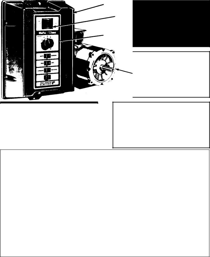
1.0 General 0 This manual familiarizes the user with the Reliance Electric Regenerative MinPaktPlus D/C V SR drive controller. (Refer to Figure 1.1 ) It describes assem/ bly and installation procedures, gives a general overview of operation, and contains information on troubleshoot/ ing. maintenance, the ordering of spare parts, and speci/ fications.
The manual should be read before performing installa/ tion or start/up activities. Also, there are certain funda/ mentals which must be kept in mind at all times. These are:
DANGER
THE DRIVE SYSTEM SHOULD BE INSTALLED, ADJUSTED AND SERVICED BY QUALIFIED ELECTRICAL MAINTENANCE PERSONNEL FA9 MILIAR WITH THE CONSTRUCTION AND OP9 ERATION OF ALL EQUIPMENT IN THE SYSTEM. PERSONAL INJURY AND/OR EQUIPMENT DAMAGE MAY OCCUR IF INDIVIDUALS ARE NOT FAMILIAR WITH THE HAZARDS RESULT9 ING FROM IMPROPER OPERATION.
DANGER
CONTROLLER EQUIPMENT IS AT LINE VOLT9 AGE WHEN A9C POWER IS CONNECTED TO THE POWER UNIT IN THE REGENERATIVE MIN9 PAK PLUS CONTROLLER. THUS A9C POWER MUST BE REMOVED FROM THE UNIT BEFORE IT IS SAFE TO TOUCH INTERNAL PARTS OF THE CONTROLLER. PERSONAL INJURY MAY RESULT UNLESS POWER IS REMOVED.
WARNING
THE NATIONAL ELECTRICAL CODE REQUIRES THAT AN N.E.C. APPROVED FUSED DISCON9 NECT SWITCH OR CIRCUIT BREAKER BE USED AHEAD OF THE CONTROLLER AND POWER TRANSFORMER (IF USED) ON THE INCOMING A9C LINE. PERSONAL INJURY MAY RESULT IF AN EASILY ACCESSIBLE MEANS OF LINE VOLTAGE DISCONNECTION IS NOT PROVIDED.
WARNING
DO NOT OPERATE THE REGENERATIVE MIN9 PAK PLUS CONTROLLER ON POWER SUP9 PLIES WITH AVAILABLE SHORT9CIRCUIT CUR9 RENTS IN EXCESS OF 1000 AMPERES FOR RATINGS OF 1 HP, OR LESS. AND 5000 AM9 PERES FOR RATINGS GREATER THAN 1 HP. DAMAGE TO EQUIPMENT AND PERSONAL IN9 JURY MAY OCCUR.
Cover
ON/OFF breaker
Faceplate
D/c motor
Figure 1.1 - Regenerative MinPak Plus Controller and Typical Motor
1
Section 2
GENERAL CONTROLLER INFORMATION
2.0 General C The Regenerative MinPak Plus DBC VKS drive controller may be applied to singleBphase dBc drive applications with ratings within the following ranges:
DFrom 1/4 to 3/4 hp with a 115 VAC, 50/60 Hz input voltage
DFrom 1/2 to 5 hp with 230 VAC, 50/60 Hz input voltage
Reliance Electric dBc motors, which may be used with the controller, may be either permanent magnet motors up to 1B1/2 hp or wound field (excited) motors up to 5 hp.
The controller provides powerBconversion and control circuits which convert the aBc line voltage into adjustable dBc voltage in order to effectively control the drive motor.
The drive package consists of three basic drive compoB nents:
D Regenerative MinPak Plus controller D Operator's control station
D AdjustableBspeed dBc motor
Optional Modification Kits conveniently expand the caB pability of the basic controller.
The Regenerative MinPak Plus controller is provided, as standard, in a NEMA Type 4/12 enclosure intended for wall or panel mounting. It is made up of a Chassis and hinged Cover. (Type 4 may be generally defined as a •washdown" design. A specific definition is given at Paragraph 2.5.) The enclosure may easily be converted into a Chassis only type configuration for panel mounting within a larger electrical enclosure. The optional Remote Control Station may then be placed on the larger encloB sure's face or some distance away.
A doubleBpole POWER ON/OFF circuit breaker is stanB dard with each Chassis and is independent of the Cover and Faceplate. A singleBpole circuit breaker in the armaB ture circuit protects the controller and motor in the event of an inverting fault.
The Regenerative MinPak Plus controller, in both NEMA Type 4/12 or Chassis configurations, is Underwriters Laboratories (U.L.) listed and Canadian Standards Association (C.S.A.) certified.
The regenerative control unit contains two fullBwave, fullB control power conversion modules. These power modB ules, along with their associated control circuitry, allow selective current flow through the motor armature in eiB ther direction under controlled conditions. The result is an SCR drive that is able to provide positive or negative torque output in either direction of motor rotation.
The controller's features are summarized in Table 2.A.
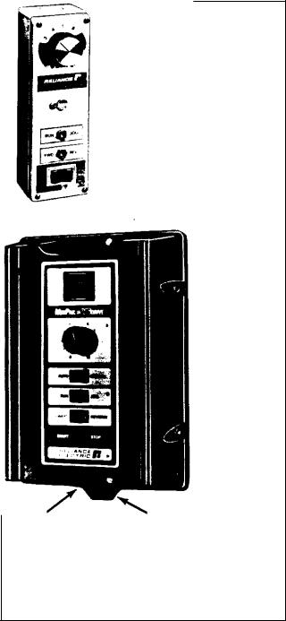
2.1 Operator's Control Station C For proper operation of the Regenerative MinPak Plus controller, it is necesB sary to use an Operator's Control Station. (Refer to FigB ure 2.1 .)The Operator Station allows the tailoring of conB trol functions for the application. These may include:
D SPEED control potentiometer D TORQUE control potentiometer D AUTO/MANUAL selector switch
D RUN/JOG selector switch
D FORWARD/REVERSE selector switch
D START/STOP selector switch
There are two basic configurations that may be selected: D Station mounted on controller Chassis Cover (local) D Station mounted as a separate unit (remote)
Nameplate |
lock lip |
Local Operator
Control Station
Figure 2.1 - Remote and Local Operator Control
Stations
2
2.1.1 Local Station C When the Station is mounted loB cally on the Cover, users may select from five standard Faceplates in order to configure a controller to a specific drive application Refer to Table 6.B which is an inclusive listing of Faceplate types, Model Numbers and functions. Assuming the Cover is properly installed, the Faceplate design maintains the NEMA Type 4/12 rating.
2.1.2 Remote Stations C Some applications may reB quire that the Operator's Control Station be remotely loB cated. Briefly, the following three steps describe what must be done:
DSelect the blank Remote Operator Station Cover Faceplate (Model 14C200).
|
Table 2.A - REGENERATIVE MINPAK PLUS FEATURES SUMMARY |
|
|
|
|
ATEGORY |
|
FEATURE |
|
|
|
Controller Functions |
|
D START/STOP |
|
|
D RUN/JOG |
|
|
D FORWARD/REVERSE |
|
|
D Speed selection (0B100%) |
|
|
D Torque selection (10B150%) |
|
|
D Full fourBquadrant operation with coastBtoBrest on stop command standard. (Dynamic |
|
|
braking available as option.) |
|
|
D 20:1 controlledBspeed range by means of armature voltage control. |
|
|
D Armature loop contactor removes power to drive motor. |
|
|
D Isolated armature voltage and current feedbacks decouples armature power from operator |
|
|
devices and provides additional noise immunity. |
|
|
D With tachometers specified in this manual, 0 5% or 1 0% speed regulation with a 95% load |
|
|
change |
|
|
D Operates and delivers rated output speed with specified regulation tolerance limits even |
|
|
with aBc line variations of 10% of nominal rated input voltage. |
|
|
D Operates without component damage even with momentary aBc line drops of -25% of |
|
|
nominal input voltage. |
|
|
|
Speed Regulation |
|
D Jumper reconnectable regulator circuits which allow armature (A) or tachometer feedback |
|
|
(T) regulation. |
|
|
D With voltage regulation, 3B5% speed regulation with 95% load change. |
|
|
D With tachometer specified, 1% speed regulation with a 95% load change. (Tachometers |
|
|
are 5PY or REB020 dBc tachometer.) |
|
|
D With tachometer specified, 0.5% speed regulation with 95% load change. (Tachometer |
|
|
is BC42.) |
|
|
|
User Adjustments |
|
D Separately adjustable forward and reverse current limits (10B150% of fullBload current). |
|
|
D Adjustable maximum speed (50B100% of base motor speed). |
|
|
D Adjustable minimum speed (0B50% of base motor speed). |
|
|
D Adjustable, separately set linear acceleration and deceleration rates (0.5B30 sec). |
|
|
|
Safety |
|
D Control circuitry guards against automatic restarting of equipment after resumption of |
|
|
interrupted aBc incoming power. |
|
|
D Regulator and operator's controls isolated from aBc line for personnel protection |
|
|
D Armature voltage and current feedback isolated to assure separation of power and |
|
|
regulator circuits. |
|
|
D Motor thermostat protection (all horsepower ratings) |
|
|
|
Hardware |
|
D Conveniently located screw terminal connections for incoming aBc and outgoing dBc |
|
|
power allow easy cable entry and connection |
|
|
D Circuit breaker causes positive opening of aBc line circuit in order to protect Power Cube |
|
|
from armature short circuit |
|
|
D Circuit breaker in armature circuit to prevent power module failure due to inverting fault. |
|
|
D Protection from momentary surges on aBc line and from dBc load transients. |
|
|
D DBc motor contactor for positive motor disconnection. |
|
|
D Contactor sequencing so that contactor closes and opens at zero armature current. |
|
|
|
3

D Order a Remote Operator Adapter Kit, Model 14C220. (This unit provides a connection point for the Remote Station .)
DSpecify a Reliance Electric Remote Operator Con< trol Station. Connect it to the controller.
Reliance Electric offers a variety of Remote Operator Sta< tions that are compatible with the Regenerative MinPak Plus controller. (Refer to Table 2.B.)
2.2D;C Drive Motors = The third component of the Re< generative MinPak Plus D<C VKS drive system is the d<c motor. Reliance Electric offers a completely power< matched drive system for the controller and the applica< tion. Thus the choice of Reliance Electric motors assures optimum performance and unmatched single<source re< sponsibility.
2.3Modification Kits = The basic capability of the con< troller can be quickly and conveniently extended with the use of a variety of optional Modification Kits. (Refer to Fig< ure 2.2.) These are:
D Dynamic Braking
D Voltage/Tachometer Follower
D Instrument Interface/Preset Speed
D Field Supply (Standard on 2, 3 and 5 hp controllers) D Auxiliary M Contact
D Test Meter Adapter
D Master Isolated Reference Receiver D Dancer Follower
Complete descriptions of each Kit are given in Section 6. Refer also to Table 6.A.
2.4 Specifications = The more important specifica< tions for the Regenerative MinPak Plus controller are listed in Table 2.C. Refer also to Table 2.D where other ratings are indicated in relation to d<c motors of specific horsepower.
2.4.1 Line Frequency = The Regenerative MinPak Plus controller is able to operate without modification from a
single<phase power source having a frequency range from 48 to 62 Hz. However, for optimum 50<Hz operation, it is recommended that two resistors be removed from the Regulator Module. (Complete details are given at Paragraph 3.9.) If the resistors are not removed, there is a slight loss of performance.
2.4.2Voltage Tolerance = The Regenerative MinPak Plus controller delivers output current and voltage as listed in Table 2.D. It will also operate within these regula< tion specifications even with incoming line voltage at10% of nominal. Furthermore, the controller will oper< ate without component damage during momentary input voltage dips down to 25% of nominal.
2.4.3Line Impedance Requirements = The standard Regenerative MinPak Plus controller contains a short<cir< cuit protection system designed to operate on plant power supplies with maximum permissible available symmetrical RMS fault currents of either 1000 or 5000 amperes, depending on the horsepower rating. (Refer to Table 2.D.)
WARNING
DO NOT OPERATE THE REGENERATIVE MIN; PAK PLUS CONTROLLER ON POWER SUP; PLIES WITH AVAILABLE SHORT;CIRCUIT CUR; RENTS IN EXCESS OF 1000 AMPERES FOR RATINGS OF 1 HP, OR LESS, AND 5000 AM; PERES FOR RATINGS GREATER THAN 1 HP. DAMAGE TO EQUIPMENT AND PERSONAL IN; JURY MAY OCCUR.
2.5 NEMA Definitions = NEMA Type 4 is generally de< fined as an indoor/outdoor enclosure that is watertight and dusttight. It is designed to protect against splash< ings and hose<directed water within specific test limita< tions.
NEMA Type 12 is generally defined as an indoor enclo< sure that is dusttight and oiltight. It is designed to resist fibers, flyings, dust, dirt and light oil splashings.
Table 2.B - REMOTE OPERATOR CONTROL STATIONS
WHEN USING A |
SPECIFY |
|
FUNCTIONS PROVIDED |
|
||
REGENERATIVE |
OPERATOR'S |
|
|
|
|
|
START/STOP |
SPEED SETTING |
RUN/JOG |
FORWARD/REVERSE |
|||
MINPAK PLUS |
STATION |
|||||
ROCKER SWITCH |
POTENTIOMETER |
SELECTOR |
SELECTOR |
|||
CONTROLLER WITH: |
MODEL |
|||||
|
|
|
|
|||
|
|
|
|
|
|
|
Basic features plus |
9C46 |
yes |
yes |
yes |
yes |
|
armature reversing |
|
|
|
|
|
|
(standard reversing |
|
|
|
|
|
|
Station) |
|
|
|
|
|
|
NEMA Type 4 Station |
9C19 |
yes |
yes |
yes |
yes |
|
for reversing |
|
|
|
|
|
|
Explosion<proof |
9C16 |
yes |
yes |
yes |
yes |
|
Station for reversing |
|
|
|
|
|
|
|
|
|
|
|
|
|
4

Field Supply
Dynamic Braking mounts behind Bracket
Auxiliary M Module mounts on center of Auxiliary Mounting Bracket
Voltage/Tachometer
Follower
or
Instrument Interface/
Preset Speed
or
Master Isolated
Reference Receiver
Module
or
Dancer Follower
Module
Remote Operator |
Test Meter Adapter |
|
|
Adapter Module |
Tachometer Feedback |
Figure 2.2 - Controller Chassis with Modification Kits
5

Table 2.C - SPECIFICATIONS
A6C Line Input Voltage
115/230 VAC (nominal)
single@phase only
Line Voltage Variation
10% of nominal
A6C Line Frequency
Single Phase, 50/60 Hz
(Jumper selectable)
Line Frequency Range
48@62 Hz
Output Voltages (armature and field)
See Table 2.D
Controller6Drive HP Range
1/4@3/4 hp (with 115 VAC input) 1/2@5 hp (with 230 VAC input)
Direction Control
Forward/Reverse
Maximum Speed Adjustment
50@100% of base motor speed (user adjustable)
Minimum Speed Adjustment
0@50% of base motor speed (user adjustable)
Operator Speed Adjustment
Infinitely adjustable with optional control pot (0@100% of base speed)
Operator Torque Adjustment
Infinitely adjustable at optional control pot (10@150% of rated load)
Controllable Speed Range
20:1
Current Limit
Factory shipped: 150% of full load User adjustable: 10@150% of full load (User separately adjustable positive and negative)
Regulation
(with 95% load change)
3@5% with voltage feedback
1.0% with specified tachometer feedback
0.5% with specified tachometer feedback
Minimum Load for Stable Operation
5%
Acceleration/Deceleration Rates
0.5@30 sec. linear time (user@adjusted separately)
Armature Circuit Overload Capacity
150% of armature current rating for 1 minute (max.)
Efficiency
(rated speed/rated load)
Controller only: 97% Complete drive including motor: 85% (typical)
Displacement Power Factor
68% (typical)
Circuit Breaker Interrupting Capacity
1000 amps to 1 hp
5000 amps 1@1/2@5 hp
Transient Protection
MOV, Output RC Circuit, and
Thyristor RC Circuits (4)
Controller Service Factor
1.0
Duty
Continuous
Storage Ambient Temperature
0°@55°C (32°-131°F)
Operational Ambient Temperature
Chassis: 0°-55°C (32°-131°F)
Cabinet: 0°-40°C (32°-104°F)
Relative Humidity (storage and operational)
5-95% (without condensation)
Operational Altitude
To 3300 ft (1000 m) above sea level without derating
Controller Enclosure Rating
NEMA Type 4 and 12 (watertight, as defined)
Controller Weight (approx.)
3/4, 1@1/2, 3 hp = 14.4 lb (6.5 kg) 5 hp = 15.1 lb (6.9 kg)
Shipping Box Weight (approx.)
3/4, 1@1/2, 3 hp = 16.4 lb (7.4 kg) 5 hp=17.1 Ib (7.8kg)
(Figures include all optional Kits)
Controller Dimensions (LWD)
14@15/16 x 9@7/8 x 7@3/8 inch (370 x 247 x 184 mm)
See Paragraph 3.9.
Typical percent shown. Exact figure dependent on motor base speed and frame size.
Assumes proper installation procedures.
6

Table 2.D - D9C MOTOR/CONTROLLER/TRANSFORMER SPECIFICATIONS
CONTROLLER |
|
|
|
|
D9C |
OPTIONAL |
POWER |
TRANSFORMER |
|||
MODEL NUMBERS |
|
|
A9C |
D9C |
ARM. |
D9C |
AMP. |
SUPPLY |
MAXIMUM |
FULL |
|
|
|
|
|
AMPS |
ARM. |
AMPS |
FIELD |
MAX. |
CAPACITY |
kVA |
LOAD |
ENCLOSED |
CHASSIS |
HP |
VAC |
(RMS) |
(VOLTS) |
(avg.) |
VOLTS |
(optional) |
|
Per Phase |
kVA |
14C30 |
14C40 |
1/4 |
115 |
.3.5 |
.90 |
.2.5 |
100 |
3.0 |
1000 |
40 |
.0.75 |
|
|
1/3 |
115 |
.5.2 |
.90 |
.3.7 |
100 |
3.0 |
1000 |
40 |
.0.75 |
|
|
1/2 |
115 |
.7.0 |
.90 |
.5.0 |
100 |
3.0 |
1000 |
40 |
1.0 |
|
|
3/4 |
115 |
10.5 |
.90 |
.7.5 |
100 |
3.0 |
1000 |
40 |
1.5 |
|
|
|
|
|
|
|
|
|
|
|
|
14C31 |
14C41 |
1/2 |
230 |
.3.5 |
180 |
.2.5 |
200 |
3.0 |
1000 |
40 |
.1.0 |
|
|
3/4 |
230 |
.5.2 |
180 |
.3.7 |
200 |
3.0 |
1000 |
40 |
.1.5 |
|
|
1 |
230 |
.7.0 |
180 |
.5.0 |
200 |
3.0 |
1000 |
40 |
.2.0 |
|
|
1/1/2 |
230 |
10.5 |
180 |
.7.5 |
200 |
3.0 |
5000 |
40 |
.3.0 |
|
|
|
|
|
|
|
|
|
|
|
|
14C32 |
14C42 |
2 |
230 |
14.0 |
180 |
10.0 |
200 |
3.0 |
5000 |
40 |
.5.0 |
|
|
3 |
230 |
21.0 |
180 |
15.0 |
200 |
3.0 |
5000 |
40 |
.5.0 |
|
|
|
|
|
|
|
|
|
|
|
|
14C33 |
14C43 |
5 |
230 |
35.0 |
180 |
25.0 |
200 |
3.0 |
5000 |
40 |
10.0 |
|
|
|
|
|
|
|
|
|
|
|
|
Standard |
|
|
|
|
|
|
|
|
|
|
|
Maximum permissible available symmetrical RMS fault current. |
|
|
|
|
|
||||||
|
|
|
|
|
|
|
|
|
|
|
|
Section 3
INSTALLATION
3.0 General 0 This Section outlines the procedures that are to be followed in order to properly plan, layout, as/ semble and install a Regenerative MinPak Plus control/ ler.
The d/c motor should be installed and wired in accor/ dance with installation instructions supplied with each drive.
There are certain precautions that should be kept in mind before planning begins. They should be considered a general checklist which, if followed, will minimize installa/ tion problems and decrease assembly time. As a user aid, they are listed here.
DANGER
THIS UNIT SHOULD BE INSTALLED, ADJUSTED AND SERVICED BY QUALIFIED ELECTRICAL MAINTENANCE PERSONNEL FAMILIAR WITH THE CONSTRUCTION AND OPERATION OF THIS TYPE OF EQUIPMENT. THEY SHOULD ALSO BE FAMILIAR WITH THE POTENTIAL HAZARDS INVOLVED. IF THIS WARNING IS NOT OBSERVED, PERSONAL INJURY OR EQUIP9 MENT DAMAGE MAY RESULT.
DANGER
BE ABSOLUTELY CERTAIN THAT A GROUND WIRE FROM THE INCOMING A9C POWER LINE IS PROPERLY CONNECTED TO THE CHASSIS GROUND TERMINAL PROVIDED. WITHOUT PROPER GROUNDING, PERSONAL INJURY MAY OCCUR.
WARNING
THE USER IS RESPONSIBLE FOR CONFORM9 ING WITH THE NATIONAL ELECTRICAL CODE WITH RESPECT TO MOTOR, CONTROLLER AND OPERATOR DEVICE INSTALLATION, WIR9 ING AND START9UP. THE USER IS ALSO RE9 SPONSIBLE FOR UNDERSTANDING AND AP9 PLYING ALL OTHER APPLICABLE LOCAL CODES WHICH GOVERN SUCH PRACTICES AS WIRING PROTECTION, GROUNDING. DISCON9 NECTS AND OVERCURRENT PROTECTION.
3.1 Planning, Layout Guidelines 0 Before actual as/ sembly and installation begins, careful layout planning must be made. This Paragraph lists recommended plan/
7
ning procedures common to all Regenerative MinPak Plus controllers. Most of the guidelines listed here must be followed in order to achieve an efficient layout.
Guideline 1 A The Regenerative MinPak Plus controller is designed primarily as a wall@ or panel@mounted unit. It is to be hung within 10° of vertical with the rear of the Chassis firmly resting against the mounting surface. (Do not position the Chassis on a horizontal surface.)
Guideline 2 A It is necessary to leave at least a 2@inch (50 mm) clearance around the three unhinged sides of the Chassis. This unobstructed area allows for proper air circulation through the fins of the heat sink. (Refer to Figure 3.1.)
Guideline 3 A Since the controller's Cover is hinged, additional clearance must be provided on the fourth side of the Chassis. (Refer to Figure 3.1.)
|
2 in. |
|
(50 mm) |
Do not |
|
place |
|
devices |
2 in. |
in this |
(50 mm) |
area. |
|
11 in. |
|
(275 mm) |
|
|
2 in. |
|
(50 mm) |
Figure 3.1 - Open Panel Minimum Mounting Distances
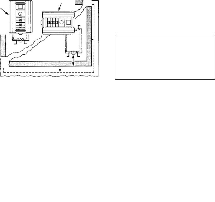
Guideline 4 A If mounting the controller within a larger enclosure, do not place it directly in a corner. Leave at least 8 inches (200 mm) from the top or 6 inches (150 mm) from the bottom of the enclosure. Also leave 8 in@ ches (200 mm) between the enclosure side wall and the unhinged side of the controller. (Refer to Figure 3.2.) Heat builds up at the cabinet's top and may exceed the permissible inside ambient temperature upper limit. At the cabinet's bottom, the unit must be high enough to al@ low air to flow upwards.
8 in.
(200 mm)
6 in.
(150 mm)
Figure 3.2 - Enclosure Mounting Minimum Distances
Guideline 5 A Regardless of the above placement guidelines, the user is responsible for providing ambient temperatures that meet the controller's specifications. For units mounted on an open panel or wall and using the standard Cover, this range is 0° to 40°C (32° to 131°F). For units mounted in a Chassis@only configura@ tion in a larger cabinet, this range is 0° to 55°C (32° to 131°F). Relative humidity must be kept between 5 and 95% without condensation if a Cover is not used.
Guideline 6 A Keep in mind that the wells, which pro@ vide incoming and outgoing wire channels, are designed to accept threaded male conduit couplings. Plan control@ ler placement on the wall or panel to allow for conduit runs. Note also that two wells are 3/4"@14 pipe threads, and three wells are 1/2"@14 pipe threads.
Guideline 7 A Because of the diagonal design of the heat sink, the Regenerative MinPak Plus controller Chas@ sis may be mounted in one of two orientations: first, with the side containing three conduit wells at the top and, se@ cond, with the same side at the right. (The Cover, if used, will swing to the left or, alternately, upward.) Refer to Fig@ ure 3.3.
hinges
hinges
Figure 3.3 - Mounting Orientations
Guideline 8 A If the controller is to be mounted in a larg@ er enclosure and if the NEMA rating of that enclosure is adequate, there is no absolute reason to use a Cover, which is shipped as standard. (This assumes that a Re@ mote Operator Station is used.) However, the environ@ ment of the application should be carefully considered before making this decision.
Using the Regenerative MinPak Plus controller without a Cover demands that the ambient environment around the Chassis be relatively clean, free of flammable or combustible vapors, chemical fumes, oil vapor, steam and/or excessive dirt and moisture.
Guideline 9 A If the controller is placed in a larger enclo@ sure, do not place it so that the Cover, if used, cannot swing open at least 90° minimum. Allowing for the full 110° swing aids subsequent installation and trouble@ shooting. (Note that the Cover may swing to the left or upward, depending on the mounting orientation. Refer to Figure 3.3.)
Guideline 10 A Do not route the tachometer feedback signal cable, if used, in the a@c or d@c conduits. Use a dedicated steel conduit fixed in the proper well. Also use the specified wire for this function.
8

Guideline 11 B The controller requires a singleAphase power supply that provides either 115 VAC or 230 VAC at 50/60 Hz. If correct voltage is not available, it will be necessary to install a transformer between the power supply and the controller.
WARNING
DO NOT OPERATE THE REGENERATIVE MIN< PAK PLUS CONTROLLER ON POWER SUP< PLIES WITH AVAILABLE SHORT<CIRCUIT CUR< RENTS IN EXCESS OF 1000 AMPERES FOR RATINGS OF 1 HP, OR LESS, AND 5000 AM< PERES FOR RATINGS GREATER THAN 1 HP. DAMAGE TO EQUIPMENT AND PERSONAL IN< JURY MAY OCCUR.
Guideline 12 B Although autoAtransformers may step up and step down aAc power supply voltage, they do not isolate the drive system from the aAc line. Users should consider using an isolation transformer if the application conditions warrant it.
Guideline 13 B The plant power supply must be of suffiA cient current capacity to support input current requireA ments of the controller. (Refer to the drive's nameplate for correct input power information.)
Guideline 14 BThe National Electrical Code requires that a 2Apole, fused disconnect switch be installed on the incoming aAc line ahead of the controller to provide branch circuit protection.
Fuses for this disconnect switch should be chosen from Table 3.A. They should be dualAelement. slow blow type, or Class K5 or RK5.
Note that the standard POWER ON/OFF circuit breaker is a doubleApole circuit breaker designed to provide overcurrent protection for the internal Power Cubes conA taining the power semiconductors. In addition, it is an electrical disconnect. However, the N.E.C. or local codes may still require that a fused disconnect device be used. An existing branch switch may provide adequate protecA tion.
It is recommended that the disconnect switch be placed within easy reach of operating and maintenance personA nel. Do not place it inside a surrounding enclosure since cabinet doors may be locked. (Consult your local codes.)
Guideline 15 B If an isolation or autoAtransformer is used ahead of the controller, the disconnect switch should be placed on the aAc power line between the powA er source and the transformer primary. Again, use a fused disconnect switch. (Do not use a circuit breaker type switch because of the high inrush of transformer equipment.) Refer to Table 3.A for sizes and types.
Guideline 16 B An isolation transformer is not necesA sary unless the application conditions require one. HowA ever, its use provides distinct advantages. With an isolaA tion transformer:
DPersonal injury is guarded against should accidenA tal contact be made with an electrical conductor from the drive.
DAAc power line disturbances, or transients, are miniA mized by an isolation transformer, thereby reducing or eliminating damage to other solidAstate equipment powerAconversion components in the controller and other userAequipment on the same aAc line.
DThe transformer provides electrical isolation beA tween the aAc power lines and the drive motor. Damaging currents may be eliminated in instances where a dAc output accidentally becomes grounded in a unit where the aAc electrical system is grounded.
For detailed information, refer to Paragraph 3.10.
Guideline 17 B If a threeAconductor incoming aAc line is being used. it is necessary to connect the GND (green/ ground) wire to the terminal provided on the Chassis. Ring type connectors are recommended. The user must be sure that the ground wire is connected to the plant ground at the source.
Guideline 18 B If the controller is mounted in an encloA sure that is not grounded, it is necessary to provide for a ground. (Personal injury may result if this practice is not followed.)
Table 3.A - TYPICAL WIRE. FUSE SIZES
|
|
|
|
|
DISCONNECT |
|
|
A<C POWER |
D<C ARMATURE |
D<C DRIVE |
FUSE SIZE |
HP |
VAC |
(min. size/insul.) |
(min. size/insul.) |
(min. size/insul.) |
(amps) |
|
|
|
|
|
|
1/4 |
115 |
No. 14 AWG 75°C |
No. 14 AWG 75°C |
No. 14 AWG 75°C |
@8 |
1/3-1/2 |
115 |
No. 14 AWG 75°C |
No. 14 AWG 75°C |
No. 14 AWG 75°C |
15 |
3/4 |
115 |
No. 12 AWG 75°C |
No. 12 AWG 75°C |
No. 14 AWG 75°C |
20 |
|
|
|
|
|
|
1/2 |
230 |
No. 14 AWG 75°C |
No. 14 AWG 75°C |
No. 14 AWG 75°C |
@8 |
3/4-1 |
230 |
No. 14 AWG 75°C |
No. 14 AWG 75°C |
No. 14 AWG 75°C |
15 |
1A1/2 |
230 |
No. 12 AWG 75°C |
No. 12 AWG 75°C |
No. 14 AWG 75°C |
20 |
2 |
230 |
No. 12 AWG 75°C |
No. 12 AWG 75°C |
No. 14 AWG 75°C |
25 |
3 |
230 |
No. 10 AWG 75°C |
No. 10 AWG 75°C |
No. 14 AWG 75°C |
35 |
5 |
230 |
No. @8 AWG 90°C |
No. @8 AWG 90°C |
No. 12 AWG 90°C |
60 |
|
|
|
|
|
|
Copper wire recommended.
Permanent magnet motors do not require field supply.
Fuses must be dualAelement, timeAdelay (slowAblow) type, or U.L. Class K5 or RK5
9
Use a 1@inch copper braid or an 8 gauge wire and con@ nect with the plant (central) ground.
The motor frame should also be grounded. In many cases it is adequate to use a screw in the conduit box near the motor .
Guideline 19 A A thermostat is used to guard against motor overload protection. It is essential to properly con@ nect the motor thermostat in series with the Operator's Control Station STOP selector switch at connections 32 and 132. (Refer to Paragraph 3.6 for specific details. Re@ fer also to Figure 3.8 in which a typical Operator's Control Station schematic is shown.)
Guideline 20 A When planning signal or control wire runs, as listed in Table 6.C, follow these practices:
D Conduits should be steel.
DIf these conduits cross 440 VAC conductors, make sure the cross is at 90°.
DDo not route signal wires through junctions or terminal boxes that contain non@signal a@c or d@c (115/230/460 V) wires.
Guideline 21 A Operational altitude above sea level may not exceed 3300 ft (1000 m). Derate horsepower 3% for each 1000 ft (300 m) above this altitude.
3.2 Mounting A This Paragraph outlines the proce@ dures to be followed in order to mount the Regenerative MinPak Plus controller . It assumes that a layout plan ex@ ists and that Guidelines 1, 2, 3, 4, 5, 7 and 9, noted in Paragraph 3.1, have been considered.
The three largest components of the Regenerative Min@ Pak Plus controller are the Chassis, the Cover and a Cov@ er Faceplate. The first two items are standard; the third is specified and ordered as an option.
If the Cover is not being used, it should be removed be$ fore mounting begins. (It may be unfastened at the hinges.)
CAUTION: The controller design requires that the Cover be lifted about 2 inches (50 mm) directly up from the Chassis before it may be swung to one side. Always be careful to lift it before hinging to the side. Damage to the unit may result if this practice is not followed.
Determine the exact placement of the Chassis on the wall or panel. (Refer to Figure 3.4 for mounting dimensions.) Scribe the panel or mark the wall. Drill four holes large enough to accept 1/4 inch mounting bolts. Scrape the paint around the holes to allow washers and bolts to make a ground contact.
Choose four 1/4"-20 lug bolts. Their length depends upon the depth of the entire mounting surface. Because of the Chassis design, only 1/8 inch (3 mm) is required between the inside of the well and the outside edge of the heat sink.
3.3 Grounding A Proper grounding practices are es@ sential to assure personal safety, to guard against electri@ cal shocks to personnel who touch the exterior surfaces of the controller or enclosures and to reduce the effects of electrical noise interference on signal@type circuits.
There are two basic types of grounds: earth and chassis.
Scrape paint around holes
to assure grounding.
a) mounting drill plan
Drill 4 holes
for 1/4º ± 20 lug screws.
b)overall dimensions
c)side view
d) top view
Figure 3.4 - Mounting Dimensions
10
Earth ground is defined as the central ground for all elec= trical and a=c power within a facility. Frequently earth ground may also be the plant, magnetics, equipment, electrical, circuit, neutral or reference ground, depend= ing on the nomenclature used at a facility.
Copper wire, preferably braided, should be used be= tween the cabinet and the earth ground connections. All ground circuits must be continuous (that is, not broken) and permanent.
Chassis ground is defined as any electrical connection to the metal body of the unit, here the controller. Since each Chassis eventually connects to earth ground, all units in a control system have a single common refer= ence point.
3.3.1 A5C Network Ground > One type of Chassis ground involves the a=c network ground. The incoming a=c power line should have three conductors: L1 (red), L2 (white on 115 V) and GND (green). The ground wire must be firmly connected to the Chassis terminal pro= vided. Use a ring connector to assure a permanent con= nection. (Refer to Figure 3.5.)
Note that the a=c ground must not in any way be broken between the power source and the Chassis. (The recom= mended disconnect switch must not break the GND conductor.)
Ground terminal (green)
Figure 3.5 - Chassis A5C Ground Terminal
3.3.2 Cover Grounding > A ground wire, supplied as standard with each Faceplate, must be connected to a bolt on the underside of the Cover, if used. (Refer to Fig= ure 3.6.) The function of this wire is to carry the ground circuit protection to the operator switches and external shell. (It must be used with both Local and Remote Con= trol Stations.)
User attaches wire here.
Figure 3.6 - Cover Ground Wire
Since the green wire is fixed by the user on a Faceplate bolt, the installation should be performed when the Face= plate is fitted. Full details are given at Paragraph 6.1 for the Local Station and Paragraph 6.2 for the Remote.
3.4 Conduits > In general, steel conduits must be used on power and signal conductors entering the controller Chassis. When properly installed, they maintain the NEMA Type 4/12 rating. Make sure to turn the connec= tions a minimum of eight turns.
The Chassis has five conduit wells, three at the top and two at the bottom. Each is dedicated to a specific func= tion. The five wells are:
D A=c incoming voltage D D=c outgoing voltage
D Tachometer feedback (optional) D Remote Station (optional)
D Process control or auto reference (optional)
Refer to Figure 3.7 for locations.
Each well has a •knockout pad'' which may be easily punched out. Make sure only those pads used with the application are removed.
If a pad is accidentally punched out, the well must be sealed in order to maintain the •wash=down'' character= istics. Use a pipe plug with Teflon tape, or equivalent sealant.
Due to space limitations, it is recommended that all wires be drawn into the controller, not the opposite.
3.5 Power Wiring > This Paragraph briefly outlines the procedures to be followed when wiring a=c power supply lines to the controller and d=c control circuits to the drive. Consult the basic connection diagram (Figure 3.8) close= ly when following these steps.
DANGER
BEFORE WIRING MAKE SURE THE A5C LINE DISCONNECT SWITCH IS LOCKED OPEN. EVEN IF POWER HAS NOT BEEN APPLIED TO THE INCOMING LINE THIS PRACTICE AS5 SURES PERSONAL SAFETY. IF NO LOCKOUT DEVICE EXISTS REMOVE THE FUSES WITH AN INSULATED TOOL AND PLACE A WARNING TAG ON THE BOX.
All interconnecting wire should primarily be sized and installed in conformance with N.E.C. or local codes. Re= fer to the controller and motor nameplates for electrical data. Typical wire sizes and types are listed in Table 3.A as a basic guideline. Note that long cable runs may re= quire that a larger gauge be used to avoid excessive volt= age drop. Use of stranded wire is also recommended.
3.5.1 A5C Wiring > Draw the a=c line conductors into the Chassis. Make sure Guidelines 1 1, 12, 13, 14, 15, 16 and 17 have been considered. Wire according to Figure 3.8.
After wiring, examine all terminals to determine that con= nections are correctly made at both ends. Confirm wire identification. Examine the firmness of the connections.
11
1/2"-14 thread |
3/4"-14 thread |
|
|
3/4"-14 thread |
|
Tach |
DAc |
AAc |
|
|
|
input |
output |
output |
|
|
|
wires |
conductors |
conductors |
|
|
|
Field wiring |
Auxiliary M |
only if Kit |
Module |
used. |
Auxiliary |
|
|
|
Bracket |
Tach
Feedback
Remote Operator |
Input |
Output |
Station |
for |
from |
input wires |
Process Control |
Auxiliary |
|
or |
M |
|
Auto Reference |
Conductor |
1/2"-14 thread |
1/2"-14 thread |
|
Figure 3.7 - Chassis Wells Wire Routing
3.5.2 D7C Wiring B The next wires to be drawn into the controller's Chassis are the dAc armature control conducA tors. If the optional Field Supply Kit is being used, the field wiring conductors will also be drawn in. The motor thermostat conductors are to be drawn in, too. All use the same conduit.
Make sure that Guideline 10 has been considered. Wire according to Figure 3.8.
WARNING
DO NOT ALLOW CONDUCTORS TO GROUND ON THE CHASSIS OR CONDUITS. CHECK IN7 TEGRITY OF ALL WIRE INSULATION BEFORE DRAWING. REMOVE ONLY ENOUGH INSULA7 TION TO MAKE A FIRM TERMINAL CONNEC7 TION. PERSONAL INJURY COULD RESULT IF A BARE WIRE TOUCHES THE CHASSIS.
Field Supply wiring should also be performed now. It is standard on 2, 3 and 5 hp controllers and optional on lower ratings. A Field Supply Kit must be installed in the controller to accept this wiring.
Motors with dualAvoltage shunt fields should be conA nected for the higher voltage. Connect:
D 90Avolt armature/100Avolt field D 180Avolt armature/200Avolt field
D For half wave connections, refer to Figure 6.12
After wiring, examine all connections to determine that they are correctly made at both ends. Confirm wire idenA tification. Examine the firmness of the connections.
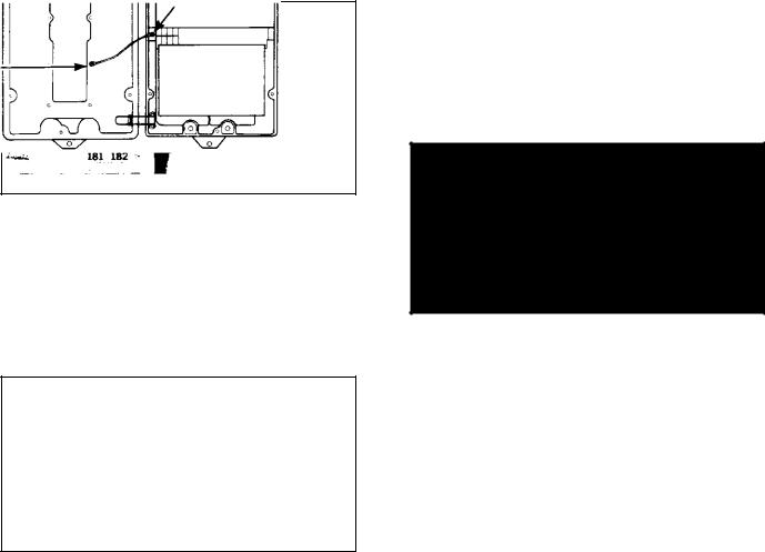
3.6 Thermal Overload Wiring B The controller is shipped without a jumper between terminals 32 and 132. The motor thermostat or an external overload must be connected to these terminals to meet local code requireA ments.
c b c c b h
h
3.7 Tachometer Feedback B The Regenerative MinA Pak Plus controller may be connected to a dAc tachomeA ter. An aAc tachometer cannot be used.
Not all drives require the use of a tachometer. This ParaA graph should be read and followed only if the specific system requires one. If your drive system does not use a tachometer, proceed to Paragraph 3.8.
The following procedures assume that Guideline 10 has been considered. These procedures are limited to pre7 paring the incoming signal wires and wiring them at the tachometer.
Note that a twisted pair signal wire must be used for the tachometer feedback circuit. It is specified in Table 6.C.
The cable run between the motor and the controller must be through a dedicated conduit. Under no circumA stances attempt to use the aAc or dAc conduits.
Wire according to Figure 3.8 and the following proceA dure.
Step 1 B Connect the tachometer wires to the terminal strip on the Module Plus (+) is the left side, minus (-) the right. Do not strip off more than 1/8 inch (3 mm) of insulaA tion since shorts occur at exposed points. Maintain the twist as long as possible.
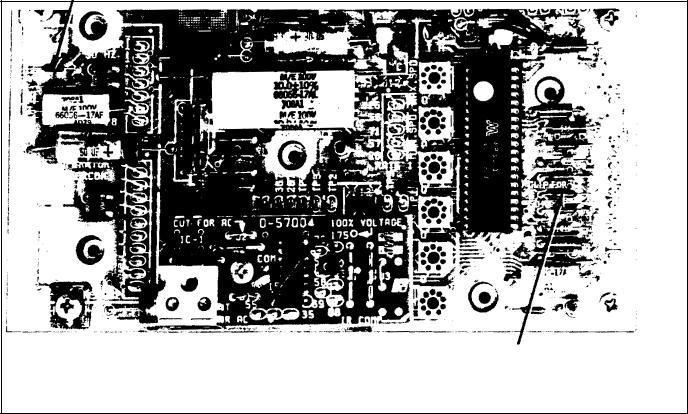
Step 2 B Locate the black pigAtail jumper on the Tachometer Module. It is to be placed on one of eight pins on the Module. Exactly which depends on the voltA age scaling factor. On the motor's nameplate, find the base speed (rpm). On the tachometer's nameplate,find the output voltage per 1000 rpm.
12

Figure . - System Connection Diagram
3
Take these two figures and relate them to Table 3.B. Read across to the right column, where the 100% voltage figC ure is indicated. Place the jumper on the Module's pin that corresponds to this figure.
Table 3.B - TACHOMETER VOLTAGE SCALING
MOTOR BASE |
|
100% |
SPEED |
TACHOMETER |
VOLTAGE |
(rpm) |
(volts/1000 rpm) |
CONNECTION |
|
|
|
1150 |
B20 VDC |
23 |
1750 |
B20 VDC |
35 |
1150 |
B50 VDC |
58 |
3450 |
B20 VDC |
69 |
1750 |
B50 VDC |
88 |
1150 |
100 VDC |
115 |
3450 |
B50 VDC |
175 |
1750 |
100 VDC |
175 |
|
|
|
Step 3 D The Feedback Jumper on the Regulator ModC ule must be connected for tachometer feedback. (Refer to Figure 3.9.) Place the Regulator Module's fixed black jumper on the pin marked T.
Figure 3.9 - Feedback Connection on Regulator Module
DANGER
IMPROPER TACHOMETER CONNECTION WITH RESPECT TO POLARITY WILL RESULT IN UN< CONTROLLED MOTOR SHAFT ACCELERATION WHICH MAY RESULT IN SEVERE PERSONAL IN< JURY AND/OR EQUIPMENT DAMAGE.
A recommended way to check the polar ty of the tachometer s to run the controller as a Voltage Regula tor wh le observ ng the tachometer output w th a d c volt meter
Step 4 D This Step assumes that the complete drive sysC tem, including the controller, has been successfully started up and debugged according to Section 4 thru Paragraph 4.4.1. It is necessary to carry out a powerCon test. Set the SPEED potentiometer at approximately 25% of full rotation. Start the drive. It should run as set. If it acC celerates to full speed, the tachometer is not providing a signal or is improperly connected.
Stop the drive, turn off all power, and check and correct the leads to the Tachometer Module's terminal strip. ReC peat the test with power on in order to confirm that proper feedback signals are being received by the regulator.
If erratic behavior continues, check the placement of the two pigCtail jumpers against Steps 2 and 3.
Step 5 D The Maximum and Minimum Speed PotenC tiometers should now be adjusted to Paragraphs 4.4.2 and 4.4.3. Be sure to follow 4.4.4, and 4.4.5.
After wiring, examine connections at both ends to make sure wire connections were correctly made. Confirm wire identification. Examine the firmness of connections.
3.8 Operator Station Wiring D Both the local Operator Control Faceplate and the Remote Operator Control StaC tion are purchased as options. Thus, they are discussed in Section 6. Modification Kits.
3.8.1 Local Faceplate D If the Regenerative MinPak Plus controller is to be used for •local'' operator control, it is necessary to mount one of five optional Faceplates in the cutout on the Chassis Cover. (''Local" is defined as having all control switches and potentiometers on the controller's Cover.)
A local configuration requires no external wiring through conduits. Complete procedures are listed at Paragraph 6.1.
3.8.2 Remote Station D If the Regenerative MinPak Plus controller is to be used for •remote" operator conC trol, it is necessary to mount an optional blank Faceplate in the cutout on the Chassis Cover. Also, an optional ReC liance Electric Remote Operator Control Station must be wired to the Remote Operator Station Kit mounted in the controller. ("Remote" is defined as not having any control switches mounted on the Chassis Faceplate.)
A remote configuration requires userCsupplied external wiring between the Station and the controller. These wires must run through a dedicated conduit and enter the controller through an assigned conduit well. (Refer to Figure 3.7.)
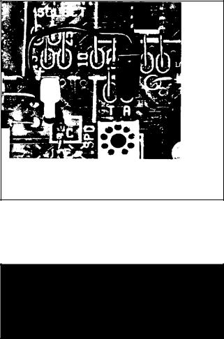
3.950<Hz Operation D There may be cases when the Regenerative MinPak Plus controller is to be operated continuously on 50 Hz. If so, two resistors should be reC moved from the Regulator Module for optimum perforC mance. (Refer to Figure 3.10.)
3.10Isolation Transformers D Although an autoCtransC former may be required because of aCc line voltage levC els, it is unable to provide a number of benefits standard with an isolation transformer. (Refer to Guideline 16.) Note also Guideline 15 concerning the position of the aCc line disconnect switch in relation to the transformer.
14
Remove resistor
Remove resistor
Figure 3.10 - 500Hz Resistor Removal
The general requirements for an isolation transformer are:
DSingle@phase
D3@8% impedance
DNonregulated
DSinusoidal output
D50/60 Hz, as required
D150% overload for 1 minute (max.)
Refer also to Table 2.D for specific information on trans@ former sizing requirements. In the Transformer column at the right. maximum kVA and full@load kVA figures are listed in relation to specific d@c motor hp/VAC ratings.
Reliance Electric offers a number of isolation transform@ ers suitable for use with the Regenerative MinPak Plus controller. (Refer to Table 3.C.)
3.11 HP/Current Jumper A It is necessary to inspect the Current Scaling/Horsepower Jumper on the Regula@ tor Module to be sure that it is connected correctly for a specific drive motor.
Step 1 A On the drive motor, locate the nameplate. Note the full@load current.
Step 2 A If current is not shown on the nameplate, refer to Table 3.D. Relate the left or center columns in the Table with known motor data. Read across to the right column marked Motor Current. This figure indicates the proper jumper connection to make on the Module, where a cor@ responding number is etched.
Table 3.C - RELIANCE ELECTRIC ISOLATION
TRANSFORMERS
|
|
PRIMARY |
SECONDARY |
ORDER |
HP |
kVA |
VAC |
VAC |
NUMBER: |
|
|
|
|
|
1/4-1/3 |
0.75 |
230/460 |
115 |
77530@10S |
1/4-1/3 |
0.75 |
575 |
115 |
Special Order |
|
|
|
|
|
1/2 |
1.0 |
230/460 |
230 |
Special Order |
1/2 |
1.0 |
575 |
115 |
Special Order |
|
|
|
|
|
3/4 |
1.5 |
115 |
115 |
77530@12V |
3/4 |
1.5 |
575 |
115 |
77530@11V |
3/4 |
1.5 |
230/460 |
115 |
77530@10V |
3/4 |
1.5 |
230/460 |
230 |
Special Order |
3/4 |
1.5 |
575 |
230 |
Special Order |
|
|
|
|
|
1 |
2.0 |
230/460 |
230 |
77530@8W |
1 |
2.0 |
575 |
230 |
Special Order |
|
|
|
|
|
1@1/2 |
3.0 |
230/460 |
230 |
77530@8X |
1@1/2 |
3.0 |
575 |
230 |
Special Order |
|
|
|
|
|
2-3 |
5.0 |
230/460 |
230 |
77530@8Y |
2-3 |
5.0 |
575 |
230 |
77530@9Y |
|
|
|
|
|
5 |
10.0 |
230/460 |
230 |
77530@8RC |
5 |
10.0 |
575 |
230 |
77530@9RC |
|
|
|
|
|
15

Table 3.D - HORSEPOWER CALIBRATION
MOTOR HP |
MOTOR CURRENT/ |
||
|
|
PIN CONNECTIONS |
|
115 VAC |
230 VAC |
||
|
|||
|
|
|
|
1/4 |
1/2 |
82.5A |
|
1/3 |
3/4 |
83.7A |
|
1/2 |
1 |
8785A |
|
3/4 |
191/2 |
87.5A |
|
: |
2 |
10A |
|
: |
3 |
15A |
|
: |
5 |
25A |
|
|
|
|
|
Step 3 : On the Regulator Module, locate the scaling pins. (Refer to Figure 3.11.) Near them, locate the black pig9tail type jumper. Do not move it if it is connected to the proper pair of pins. If it must be reconnected, carefully lift it straight up and off the pins. Slide the connector straight down over the proper set of pins.
Figure 3.11 - HP/Current Scaling Pins
Section 4
START8UP AND ADJUSTMENT
4.0 General : This Section provides start9up and ad9 justment procedures to be followed after the assembly and installation of the controller is complete. All initial op9 eration checks and final adjustments to the controller must be made in conformance to the procedures, warn9 ings and recommendations listed here.
DANGER
THE REGENERATIVE MINPAK PLUS CONTROL8 LER IS AT LINE VOLTAGE WHEN A8C LINE POW8 ER IS CONNECTED TO THE POWER UNIT IN8 SIDE THE CONTROLLER. THE OPERATOR'S POWER ON/OFF CIRCUIT BREAKER DOES NOT REMOVE A8C LINE POWER FROM THE UNIT. BEFORE WORKING ON, OR TOUCHING ANY INTERNAL PARTS F, THE CONTROLLER, REMOVE INCOMING A8C LINE POWER AT THE MAIN DISCONNECT SWITCH. PERSONAL IN8 JURY MAY RESULT IF THIS IS NOT FOLLOWED.
DANGER
DURING INITIAL START8UP, THE CONTROLLER AND ITS ASSOCIATED EQUIPMENT MUST BE OPERATED AND/OR ADJUSTED ONLY BY QUALIFIED ELECTRICAL MAINTENANCE PER8 SONNEL. THESE INDIVIDUALS SHOULD BE FA8 MILIAR WITH THE DESIGN AND OPERATION OF THIS EQUIPMENT AND WITH THE HAZARDS INVOLVED. PERSONAL INJURY AND/OR DAM8 AGE TO THE CONTROLLER COULD RESULT FROM UNFAMILIARITY.
Figure 4.1 indicates typical areas in the controller that should be examined as noted in these paragraphs.
4.1 Power Off Inspection : It is necessary to make a superficial inspection of the Regenerative MinPak Plus controller and its associated units. The purpose of this check is to look for possible physical damage or improp9 er connections. These procedures assume that the a9c incoming line is locked off and that the load is uncoupled from the motor.
Step 1 : Inspect the firmness of motor connections. There should be no broken insulation on power cables since conductor grounding could cause damage. Make sure the ground strap between the motor frame and plant (earth) ground is firmly fixed.
Step 2 : If a formal installation and wiring inspection was not carried out, it is recommended that an extensive one be done before any other start9up procedures are followed. (Discovery of wiring errors and/or improper or incomplete assembly will save valuable time later. Refer to the specific System's layout prints.)
Step 3 : Even if there had been a final inspection, in9 spect all wiring, a9c incoming, d9c outgoing, feedback, signal and grounding, for proper and firm connections Any connection error in wiring can cause damage or a malfunction when power is applied. Any short to building ground in signal wiring can also cause damage. Make sure the open panel or the enclosure is connected to plant (earth) ground.
Step 4 : Make a final check that the plant power supply feeding the a9c line is the proper voltage and frequency.
Step 5 : Use an ohmmeter to determine if a ground ex9 ists between a9c input conductors and the Chassis. Also determine if a ground exists between d9c output conduc9 tors and the Chassis. If a ground exists, it must be found and removed before proceeding.
16
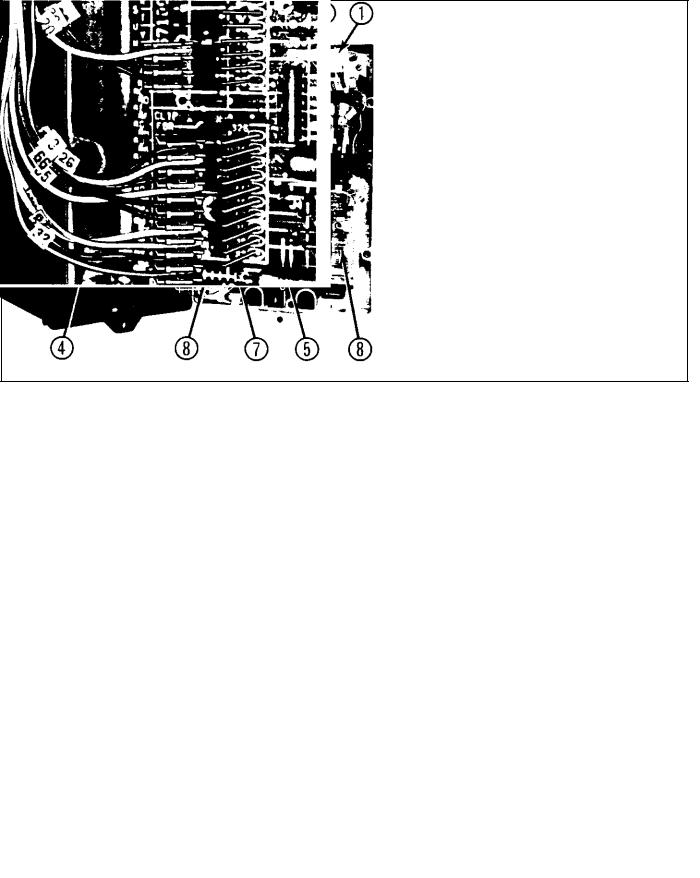
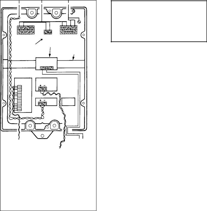
1.Incoming a?c: conductor identifications; possible grounds; Chassis ground; firm connections.
2.Outgoing d?c: same as 1, above.
3.Incoming tachometer: twisted wire rout? ing; +/@ connections at both ends; firmly seated Module; possible shorts at con? nector strip.
4.Cover: standard ground wire connected?
5.Kits: firmly seated Module; one pin thru each collar; firm properly routed wiring at connector strip; possible shorts.
6.Field Kit: completed wiring from drive's F1/F2; wiring to 51/52.
7.Remote Station: wiring identification at both ends; required twists; possible shorts.
8.Possible jumper removal: See Figure 7.6.
Fi ur 4.1 - Insp tion Ar as in Cov r Chassis
4.2 Pow r O A justm nts @ There are a number of static adjustments that are to be made in order to tailor the controller for a specific drive's needs. This work may only be performed when the a?c line power is removed at the main disconnect switch. Also, these steps should be carried out by an individual who is familiar with elec? tronic equipment.
4.2.1 Controll r Insp tion @ The object of this in? spection is to be sure that the Modification Kits are prop? erly mounted and connected with the Regulator Module. Full details of the Kits are included in Section 6.
St p 1 @ Open the Cover of the controller. Be sure to lift it directly up about 2 inches (50 mm) before swinging the Cover on its hinges.
St p 2 @ Inspect the Regulator Module. By gently press? ing a corner, determine that it is firmly seated on its sup? ports. Gently press all plastic connectors that mate with the Module. If any are loose, seat them firmly. If any are unseated, connect them.
St p 3 @ Inspect all plug?in Modification Kits. Test each for a firm mounting condition.
Each should be mechanically connected to the Regula? tor Module by means of a mounting post screw. Each should be electrically connected to the Module by a se? ries of parallel pins. If any of the pins are bent, improper operation results. Examine the pins to make sure they are perfectly parallel. Only one pin may fit through a hole in the Kit.
St p 4 @ Inspect all screw terminal connections on the Modification Kits. Make sure the wires are firmly con? nected. Also make sure that there is enough insulation on the wires to prevent a short between the conductors.
St p 5 @ Inspect the signal wiring from the Operator's Control Station. If a Local Station is used on the Cover, there are two connectors that mate with the Regulator Module at pins 32 (RED) and 28 (GRN). (See Figure 4.2.)
Fi ur 4.2 - Lo al Fa plat Conn tors
17
 Loading...