


 Loading...
MSR42, GuardShield Micro 400 and Safe 2/Safe 4 Light Curtains
Configuration and Diagnostic Software Tool
User Manual
Important User Information
Because of the variety of uses for the products described in this publication, those responsible for the application and use of this control equipment must satisfy themselves that all necessary steps have been taken to assure that each application and use meets all performance and safety requirements, including any applicable laws, regulations, codes and standards.
The illustrations, charts, sample programs and layout examples shown in the guide are intended solely for purposes of example. Since there are many variables and requirements associated with any particular installation, Rockwell Automation does not assume responsibility or liability (to include intellectual property liability) for actual use based upon the examples shown in this publication.
Rockwell Automation publication SGI-1.1, Safety Guidelines for the Application, Installation and Maintenance of Solid-State Control (available from your local Rockwell Automation sales office), describes some important differences between solid-state equipment and electromechanical devices that should be taken into consideration when applying products such as those described in this publication.
Reproduction of the contents of this copyrighted publication, in whole or part, without written permission of Rockwell Automation, is prohibited.
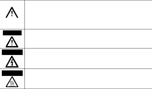
Throughout this manual we use notes to make you aware of safety considerations:
|
WARNING |
|
Identifies information about practices or circumstances that can cause an explosion in |
||
|
|
|
|
|
a hazardous environment, which may lead to personal injury or death, property |
|
|
|
|
||
|
|
|
|
|
damage, or economic loss. |
|
|
|
|
|
|
|
|
|
|
|
|
|
|
|
|
|
|
|
|
|
|
|
Identifies information that is critical for successful application and understanding of |
|
IMPORTANT |
|
|||
|
|
the product. |
|||
|
|
|
|
|
|
ATTENTION Identifies information about practices or circumstances that can lead to personal  injury or death, property damage, or economic loss. Attentions help you identify a hazard, avoid a hazard, and recognize the consequences.
SHOCK HAZARD Labels may be on or inside the equipment (for example, drive or motor) to alert people that dangerous voltage may be present.
BURN HAZARD Labels may be on or inside the equipment (for example, drive or motor) to alert people that surfaces may reach dangerous temperatures.
It is recommended that you save this user manual for future use.

Light Curtain Multi-Function Control Module User Manual
I
These products can only achieve their function as a safety controller module, if the instructions given in this instruction manual and the within mentioned documents are exactly followed, as well as consulting the valid laws and regulations at the time of installation.
Should these instructions not be carefully followed, serious injury or death may occur. The installer or system integrator will be fully responsible for a safe integration of this product. In this case Rockwell Automation, or any other party who may have distributed the software will not be liable for any damages.
The configuration of a GuardShield Micro 400 or Safe 2/4 with the MSR42 controller may only be performed by authorized personnel. The configuration of every controller must correspond to the requirements of the risk analysis for the monitoring of every application. An incorrect, or insufficient configuration may lead to serious injury or even death.
To configure a unit mentioned above, a password and an Optical Interface are necessary. Both of these must only be made available to authorized personnel.
This instruction manual is part of the controller module MSR42, GuardShield Micro 400 and Safe 2/4. It must be kept accessible together with the other machine documentation during its entire life cycle for all personnel responsible for assembly, installation, operation and maintenance.
All details reported by the program are for guidance only. Rockwell Automation does not give any warranty for calculations, general information, prices or technical details about correctness and completeness.
In the interests of continual technical advancement, Rockwell Automation reserve the right to amend the specification of the products and of the prices detailed in this software without prior notice. For further information contact your nearest Rockwell Automation sales office or Allen-Bradley distributor.
This software is provided “as is” without warranty of any kind either expressed or implied, including but not limited to the implied warranties merchantability and fitness for a particular purpose. The entire risk as to the quality and performance of the product is with you. Should the product prove defective, you assume the cost of all necessary servicing or error correction. Rockwell Automation does not warrant that the functions contained in the software will meet your requirements or that the operation of the software will be uninterrupted or error free.
In no event shall Rockwell Automation, or any other party who may have distributed the software as permitted above, be liable for damages, including any general, special, incidental, or consequential damages arising out of the use or inability to use the software (including but not limited to loss of data or data being rendered inaccurate or losses sustained by you or third parties or failure of the software to operate with any other products), even if such holder or other party has been advised of the possibility of such damages.
TÜV Rheinland Product Safety GmbH, has tested the functions and the safety relevant adjustment possibilities of this software, and confirmed the basic correct functioning of all adjustment possibilities.
Remark:
Obviously this program could not be tested with every type of computer or operating system. For that reason every result has to be proved for plausibility. Every calculation of this program is based on standards DIN EN ISO 13855 (2010) and EN 61496-2. Special applications with their specific standards as well as country specific directions are not taken into account. Therefore the user is responsible for the application of this program.
Original instructions |
1 |

Light Curtain Multi-Function Control Module User Manual
Content
Introduction . . . . . . . . . . . . . . . . . . . . . . . . . . . . . . . . . . . . . . . . . . . . . . . . . . . . . . . . . . . . . . . . . . . . . . . . . . . . . . . . . . . . . . . . . . . . . . . 2
Special Features . . . . . . . . . . . . . . . . . . . . . . . . . . . . . . . . . . . . . . . . . . . . . . . . . . . . . . . . . . . . . . . . . . . . . . . . . . . . . . . . . . . . . . . . . . . . . . . . . . . . . . . . . . . . . . . . . . . . . . 2
Introduction . . . . . . . . . . . . . . . . . . . . . . . . . . . . . . . . . . . . . . . . . . . . . . . . . . . . . . . . . . . . . . . . . . . . . . . . . . . . . . . . . . . . . . . . . . . . . . . 3
Special Features . . . . . . . . . . . . . . . . . . . . . . . . . . . . . . . . . . . . . . . . . . . . . . . . . . . . . . . . . . . . . . . . . . . . . . . . . . . . . . . . . . . . . . . . . . . . . . . . . . . . . . . . . . . . . . . . . . . . . . 3
Installation . . . . . . . . . . . . . . . . . . . . . . . . . . . . . . . . . . . . . . . . . . . . . . . . . . . . . . . . . . . . . . . . . . . . . . . . . . . . . . . . . . . . . . . . . . . . . . . . 3
Preparation . . . . . . . . . . . . . . . . . . . . . . . . . . . . . . . . . . . . . . . . . . . . . . . . . . . . . . . . . . . . . . . . . . . . . . . . . . . . . . . . . . . . . . . . . . . . . . . . . . . . . . . . . . . . . . . . . . . . . . . . . . 3
Operating Systems . . . . . . . . . . . . . . . . . . . . . . . . . . . . . . . . . . . . . . . . . . . . . . . . . . . . . . . . . . . . . . . . . . . . . . . . . . . . . . . . . . . . . . . . . . . . . . . . . . . . . . . . . . . . . . . . . . . . 4 Installation Configuration and Diagnostic Software . . . . . . . . . . . . . . . . . . . . . . . . . . . . . . . . . . . . . . . . . . . . . . . . . . . . . . . . . . . . . . . . . . . . . . . . . . . . . . . . . . . . . 4
Installation USB driver for Optical Interface . . . . . . . . . . . . . . . . . . . . . . . . . . . . . . . . . . . . . . . . . . . . . . . . . . . . . . . . . . . . . . . . . . . . . . . . . . . . . . . . . . . . . . . . . . . . 8
Program start . . . . . . . . . . . . . . . . . . . . . . . . . . . . . . . . . . . . . . . . . . . . . . . . . . . . . . . . . . . . . . . . . . . . . . . . . . . . . . . . . . . . . . . . . . . . . . . . . . . . . . . . . . . . . . . . . . . . . . . . 8
Optical Interface . . . . . . . . . . . . . . . . . . . . . . . . . . . . . . . . . . . . . . . . . . . . . . . . . . . . . . . . . . . . . . . . . . . . . . . . . . . . . . . . . . . . . . . . . . . 8
Configuration Tool for GuardShield Safe 2/Safe 4 Light Curtains . . . . . . . . . . . . . . . . . . . . . . . . . . . . . . . . . . . . . . . . . . . . . . . 9
Introduction . . . . . . . . . . . . . . . . . . . . . . . . . . . . . . . . . . . . . . . . . . . . . . . . . . . . . . . . . . . . . . . . . . . . . . . . . . . . . . . . . . . . . . . . . . . . . . . . . . . . . . . . . . . . . . . . . . . . . . . . . 9 Safety Distance Calculator . . . . . . . . . . . . . . . . . . . . . . . . . . . . . . . . . . . . . . . . . . . . . . . . . . . . . . . . . . . . . . . . . . . . . . . . . . . . . . . . . . . . . . . . . . . . . . . . . . . . . . . . . . . 11 Safe 2/Safe 4 Diagnostics . . . . . . . . . . . . . . . . . . . . . . . . . . . . . . . . . . . . . . . . . . . . . . . . . . . . . . . . . . . . . . . . . . . . . . . . . . . . . . . . . . . . . . . . . . . . . . . . . . . . . . . . . . . . . 12
Configuration Tool for MSR42 . . . . . . . . . . . . . . . . . . . . . . . . . . . . . . . . . . . . . . . . . . . . . . . . . . . . . . . . . . . . . . . . . . . . . . . . . . . . . . 13
Introduction . . . . . . . . . . . . . . . . . . . . . . . . . . . . . . . . . . . . . . . . . . . . . . . . . . . . . . . . . . . . . . . . . . . . . . . . . . . . . . . . . . . . . . . . . . . . . . . . . . . . . . . . . . . . . . . . . . . . . . . . 13
Starting MSR42 Configuration Tool . . . . . . . . . . . . . . . . . . . . . . . . . . . . . . . . . . . . . . . . . . . . . . . . . . . . . . . . . . . . . . . . . . . . . . . . . . . . . . . . . . . . . . . . . . . . . . . . . . 14
The menu bar . . . . . . . . . . . . . . . . . . . . . . . . . . . . . . . . . . . . . . . . . . . . . . . . . . . . . . . . . . . . . . . . . . . . . . . . . . . . . . . . . . . . . . . . . . . . . . . . . . . . . . . . . . . . . . . . . . . . . . . 15
Menu “File” . . . . . . . . . . . . . . . . . . . . . . . . . . . . . . . . . . . . . . . . . . . . . . . . . . . . . . . . . . . . . . . . . . . . . . . . . . . . . . . . . . . . . . . . . . . . . . . . . . . . . . . . . . . . . . . . . . . . . . . . . 16 Menu “Options” . . . . . . . . . . . . . . . . . . . . . . . . . . . . . . . . . . . . . . . . . . . . . . . . . . . . . . . . . . . . . . . . . . . . . . . . . . . . . . . . . . . . . . . . . . . . . . . . . . . . . . . . . . . . . . . . . . . . . 16
Menu “Help” . . . . . . . . . . . . . . . . . . . . . . . . . . . . . . . . . . . . . . . . . . . . . . . . . . . . . . . . . . . . . . . . . . . . . . . . . . . . . . . . . . . . . . . . . . . . . . . . . . . . . . . . . . . . . . . . . . . . . . . . 18
Main window . . . . . . . . . . . . . . . . . . . . . . . . . . . . . . . . . . . . . . . . . . . . . . . . . . . . . . . . . . . . . . . . . . . . . . . . . . . . . . . . . . . . . . . . . . . . . . . . . . . . . . . . . . . . . . . . . . . . . . . 18
Tab “Design” . . . . . . . . . . . . . . . . . . . . . . . . . . . . . . . . . . . . . . . . . . . . . . . . . . . . . . . . . . . . . . . . . . . . . . . . . . . . . . . . . . . . . . . . . . . . . . . . . . . . . . . . . . . . . . . . . . . . . . . . 18
Tab “Diagnosis” . . . . . . . . . . . . . . . . . . . . . . . . . . . . . . . . . . . . . . . . . . . . . . . . . . . . . . . . . . . . . . . . . . . . . . . . . . . . . . . . . . . . . . . . . . . . . . . . . . . . . . . . . . . . . . . . . . . . . 21 Tab “Application info” . . . . . . . . . . . . . . . . . . . . . . . . . . . . . . . . . . . . . . . . . . . . . . . . . . . . . . . . . . . . . . . . . . . . . . . . . . . . . . . . . . . . . . . . . . . . . . . . . . . . . . . . . . . . . . . 22
Possible Configurations . . . . . . . . . . . . . . . . . . . . . . . . . . . . . . . . . . . . . . . . . . . . . . . . . . . . . . . . . . . . . . . . . . . . . . . . . . . . . . . . . . . . . . . . . . . . . . . . . . . . . . . . . . . . . . 24
Micro 400 Light Curtain . . . . . . . . . . . . . . . . . . . . . . . . . . . . . . . . . . . . . . . . . . . . . . . . . . . . . . . . . . . . . . . . . . . . . . . . . . . . . . . . . . . . . . . . . . . . . . . . . . . . . . . . . . . . . 25
One Device (2 NC) . . . . . . . . . . . . . . . . . . . . . . . . . . . . . . . . . . . . . . . . . . . . . . . . . . . . . . . . . . . . . . . . . . . . . . . . . . . . . . . . . . . . . . . . . . . . . . . . . . . . . . . . . . . . . . . . . 27 One or Two Device (OSSDs) . . . . . . . . . . . . . . . . . . . . . . . . . . . . . . . . . . . . . . . . . . . . . . . . . . . . . . . . . . . . . . . . . . . . . . . . . . . . . . . . . . . . . . . . . . . . . . . . . . . . . . . . . 27
Safety override . . . . . . . . . . . . . . . . . . . . . . . . . . . . . . . . . . . . . . . . . . . . . . . . . . . . . . . . . . . . . . . . . . . . . . . . . . . . . . . . . . . . . . . . . . . . . . . . . . . . . . . . . . . . . . . . . . . . . . 28
Muting Micro 400 . . . . . . . . . . . . . . . . . . . . . . . . . . . . . . . . . . . . . . . . . . . . . . . . . . . . . . . . . . . . . . . . . . . . . . . . . . . . . . . . . . . . . . . . . . . . . . . . . . . . . . . . . . . . . . . . . . . 30
Muting other device (OSSDs) . . . . . . . . . . . . . . . . . . . . . . . . . . . . . . . . . . . . . . . . . . . . . . . . . . . . . . . . . . . . . . . . . . . . . . . . . . . . . . . . . . . . . . . . . . . . . . . . . . . . . . . . 31 Function “EDM” + “Start Release” . . . . . . . . . . . . . . . . . . . . . . . . . . . . . . . . . . . . . . . . . . . . . . . . . . . . . . . . . . . . . . . . . . . . . . . . . . . . . . . . . . . . . . . . . . . . . . . . . . . . 31
Function “Stop delay” . . . . . . . . . . . . . . . . . . . . . . . . . . . . . . . . . . . . . . . . . . . . . . . . . . . . . . . . . . . . . . . . . . . . . . . . . . . . . . . . . . . . . . . . . . . . . . . . . . . . . . . . . . . . . . . . 32
Download, Verify & Upload . . . . . . . . . . . . . . . . . . . . . . . . . . . . . . . . . . . . . . . . . . . . . . . . . . . . . . . . . . . . . . . . . . . . . . . . . . . . . . . . . . . . . . . . . . . . . . . . . . . . . . . . . . 32
PC ÖMSR42 (Download) . . . . . . . . . . . . . . . . . . . . . . . . . . . . . . . . . . . . . . . . . . . . . . . . . . . . . . . . . . . . . . . . . . . . . . . . . . . . . . . . . . . . . . . . . . . . . . . . . . . . . . . . . . 32 Verify download . . . . . . . . . . . . . . . . . . . . . . . . . . . . . . . . . . . . . . . . . . . . . . . . . . . . . . . . . . . . . . . . . . . . . . . . . . . . . . . . . . . . . . . . . . . . . . . . . . . . . . . . . . . . . . . . . . . . . 35 Configuration Protection . . . . . . . . . . . . . . . . . . . . . . . . . . . . . . . . . . . . . . . . . . . . . . . . . . . . . . . . . . . . . . . . . . . . . . . . . . . . . . . . . . . . . . . . . . . . . . . . . . . . . . . . . . . . 36 MSR42 ÖPC (Upload) . . . . . . . . . . . . . . . . . . . . . . . . . . . . . . . . . . . . . . . . . . . . . . . . . . . . . . . . . . . . . . . . . . . . . . . . . . . . . . . . . . . . . . . . . . . . . . . . . . . . . . . . . . . . . 38 Muting . . . . . . . . . . . . . . . . . . . . . . . . . . . . . . . . . . . . . . . . . . . . . . . . . . . . . . . . . . . . . . . . . . . . . . . . . . . . . . . . . . . . . . . . . . . . . . . . . . . . . . . . . . . . . . . . . . . . . . . . . . . . . 38 General . . . . . . . . . . . . . . . . . . . . . . . . . . . . . . . . . . . . . . . . . . . . . . . . . . . . . . . . . . . . . . . . . . . . . . . . . . . . . . . . . . . . . . . . . . . . . . . . . . . . . . . . . . . . . . . . . . . . . . . . . . . . . 38 Muting lamp . . . . . . . . . . . . . . . . . . . . . . . . . . . . . . . . . . . . . . . . . . . . . . . . . . . . . . . . . . . . . . . . . . . . . . . . . . . . . . . . . . . . . . . . . . . . . . . . . . . . . . . . . . . . . . . . . . . . . . . . 39
Muting sensors . . . . . . . . . . . . . . . . . . . . . . . . . . . . . . . . . . . . . . . . . . . . . . . . . . . . . . . . . . . . . . . . . . . . . . . . . . . . . . . . . . . . . . . . . . . . . . . . . . . . . . . . . . . . . . . . . . . . . . 39
Mute dependant override function . . . . . . . . . . . . . . . . . . . . . . . . . . . . . . . . . . . . . . . . . . . . . . . . . . . . . . . . . . . . . . . . . . . . . . . . . . . . . . . . . . . . . . . . . . . . . . . . . . . . 39 Sensor output delay function . . . . . . . . . . . . . . . . . . . . . . . . . . . . . . . . . . . . . . . . . . . . . . . . . . . . . . . . . . . . . . . . . . . . . . . . . . . . . . . . . . . . . . . . . . . . . . . . . . . . . . . . . 39 Muting with enable signal . . . . . . . . . . . . . . . . . . . . . . . . . . . . . . . . . . . . . . . . . . . . . . . . . . . . . . . . . . . . . . . . . . . . . . . . . . . . . . . . . . . . . . . . . . . . . . . . . . . . . . . . . . . . 40 Muting disable function . . . . . . . . . . . . . . . . . . . . . . . . . . . . . . . . . . . . . . . . . . . . . . . . . . . . . . . . . . . . . . . . . . . . . . . . . . . . . . . . . . . . . . . . . . . . . . . . . . . . . . . . . . . . . . 40 Safety light curtain interruption monitoring function . . . . . . . . . . . . . . . . . . . . . . . . . . . . . . . . . . . . . . . . . . . . . . . . . . . . . . . . . . . . . . . . . . . . . . . . . . . . . . . . . . . 40 Muting time recorder . . . . . . . . . . . . . . . . . . . . . . . . . . . . . . . . . . . . . . . . . . . . . . . . . . . . . . . . . . . . . . . . . . . . . . . . . . . . . . . . . . . . . . . . . . . . . . . . . . . . . . . . . . . . . . . . 41 Setup: 2 sensor T-type . . . . . . . . . . . . . . . . . . . . . . . . . . . . . . . . . . . . . . . . . . . . . . . . . . . . . . . . . . . . . . . . . . . . . . . . . . . . . . . . . . . . . . . . . . . . . . . . . . . . . . . . . . . . . . . 41
Setup: four sensor T-type . . . . . . . . . . . . . . . . . . . . . . . . . . . . . . . . . . . . . . . . . . . . . . . . . . . . . . . . . . . . . . . . . . . . . . . . . . . . . . . . . . . . . . . . . . . . . . . . . . . . . . . . . . . . . 43
2 |
Original instructions |

Light Curtain Multi-Function Control Module User Manual
Setup: two sensor L-type . . . . . . . . . . . . . . . . . . . . . . . . . . . . . . . . . . . . . . . . . . . . . . . . . . . . . . . . . . . . . . . . . . . . . . . . . . . . . . . . . . . . . . . . . . . . . . . . . . . . . . . . . . . . . 45
Setup: two sensor T-type with enable signal . . . . . . . . . . . . . . . . . . . . . . . . . . . . . . . . . . . . . . . . . . . . . . . . . . . . . . . . . . . . . . . . . . . . . . . . . . . . . . . . . . . . . . . . . . . . 48 Blanking . . . . . . . . . . . . . . . . . . . . . . . . . . . . . . . . . . . . . . . . . . . . . . . . . . . . . . . . . . . . . . . . . . . . . . . . . . . . . . . . . . . . . . . . . . . . . . . . . . . . . . . . . . . . . . . . . . . . . . . . . . . . 51
Teach-in Blanking mode . . . . . . . . . . . . . . . . . . . . . . . . . . . . . . . . . . . . . . . . . . . . . . . . . . . . . . . . . . . . . . . . . . . . . . . . . . . . . . . . . . . . . . . . . . . . . . . . . . . . . . . . . . . . . 52
Fixed Blanking mode . . . . . . . . . . . . . . . . . . . . . . . . . . . . . . . . . . . . . . . . . . . . . . . . . . . . . . . . . . . . . . . . . . . . . . . . . . . . . . . . . . . . . . . . . . . . . . . . . . . . . . . . . . . . . . . . 52 Floating Blanking mode . . . . . . . . . . . . . . . . . . . . . . . . . . . . . . . . . . . . . . . . . . . . . . . . . . . . . . . . . . . . . . . . . . . . . . . . . . . . . . . . . . . . . . . . . . . . . . . . . . . . . . . . . . . . . . 53 Combining Blanking modes . . . . . . . . . . . . . . . . . . . . . . . . . . . . . . . . . . . . . . . . . . . . . . . . . . . . . . . . . . . . . . . . . . . . . . . . . . . . . . . . . . . . . . . . . . . . . . . . . . . . . . . . . . 54 Indication of Blanking . . . . . . . . . . . . . . . . . . . . . . . . . . . . . . . . . . . . . . . . . . . . . . . . . . . . . . . . . . . . . . . . . . . . . . . . . . . . . . . . . . . . . . . . . . . . . . . . . . . . . . . . . . . . . . . 54 Activating blanking . . . . . . . . . . . . . . . . . . . . . . . . . . . . . . . . . . . . . . . . . . . . . . . . . . . . . . . . . . . . . . . . . . . . . . . . . . . . . . . . . . . . . . . . . . . . . . . . . . . . . . . . . . . . . . . . . . 54 Configuring the Blanking Function . . . . . . . . . . . . . . . . . . . . . . . . . . . . . . . . . . . . . . . . . . . . . . . . . . . . . . . . . . . . . . . . . . . . . . . . . . . . . . . . . . . . . . . . . . . . . . . . . . . 54
Appendix . . . . . . . . . . . . . . . . . . . . . . . . . . . . . . . . . . . . . . . . . . . . . . . . . . . . . . . . . . . . . . . . . . . . . . . . . . . . . . . . . . . . . . . . . . . . . . . . . 56
Frequently Asked Questions (FAQ) . . . . . . . . . . . . . . . . . . . . . . . . . . . . . . . . . . . . . . . . . . . . . . . . . . . . . . . . . . . . . . . . . . . . . . . . . . . . . . . . . . . . . . . . . . . . . . . . . . . 56
1. Introduction
The “Configuration and Diagnostic Software” developed by Rockwell Automation is designed for the most varying of applications. It can be used as a truly active work-instrument by technicians, safety experts, maintenance personnel, designers, process controllers as well as purchase managers.
The program is primarily used to configure the Rockwell Automation GuardShield and MSR42 products but can also be used for diagnosis functions together with the “Optical Interface”. The “Configuration and Diagnostic Software” is delivered with every Optical Interface and is also available free of charge, on the Internet at www.ab.com.
This software description manual covers the following Rockwell Automation products:
•Safety Relay MSR42
•Safety Light Curtain Micro 400
•Safety Light Curtain Safe 2
•Safety Light Curtain Safe 4
With the help of this software, functions like start mode (automatic or manual), stop delay, EDM, and “Safety Override” can be chosen easily and configured graphically.
The software provides technical data and various application information of all supported applications.
1.1. Special Features
The features of the Configuration Tool are:
•Simple installation
•Simple graphical user interface
•Easy to use
•No programming knowledge necessary
•Diagnosis tool integrated
•Detailed safety information integrated
•Optical interface communication software included
•Password protected MSR42 configuration
•Enables process control
•Optimize maintenance services
•Light curtain configuration and diagnostics
•Visual indication of terminal assignment
•Safety distance calculation
•Free download at www.ab.com
Original instructions |
3 |
Light Curtain Multi-Function Control Module User Manual
2. Installation
2.1. Preparation
Before connecting the USB optical interface to the computer, the software configuration tool has to be installed (See chapter 2.3 on page 4).
During installation the USB driver software is copied to the hard drive. After this the USB Optical Interface can be connected to the computer and the driver software installed (See chapter 2.3 on page 4).
Before installation of the newest version of the Configuration and Diagnostic Software, Rockwell Automation recommends that the previous versions be uninstalled. This is carried out using the following link:
Windows-Start — Program — Rockwell Automation applications — Configuration and Diagnostic Software — Additional Configuration and Diagnostic Software — Uninstall Configuration and Diagnostic Software.
Make sure that all programs active in the background on your PC are shut down. These may disturb the correct “Set up” installation of the
Configuration and Diagnostic Software.
2.2. Operating Systems
The Configuration and Diagnostic Software works on the following operating systems:
•Windows 2000
•Windows XP SP1, SP2
•Windows Vista
2.3. Installation Configuration and Diagnostic Software
Start installation with the following link
SetupDiagnosticAndConfiguration_V130.exe
The program is available on the Rockwell Automation CD delivered with the the Optical Interface (445L-AF6150). The newest release is also available for free on www.ab.com.
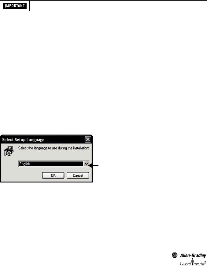
Follow the instructions of the setup program (Figure 1 ... Figure 9). This manual refers to proposed settings for the setup program. The blue marked arrows aid to a successful installation of this software.
Figure 1: Language selection
4 |
Original instructions |
Light Curtain Multi-Function Control Module User Manual
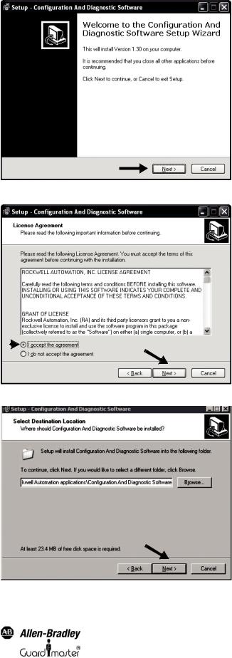
Figure 2: Welcome window for installation
|
|
2 |
|
|
|
1 |
|
|
|
|
|
Figure 3: License agreement |
|
|
Figure 4: Select target folder of installation. Default:C:\ProgramFiles\RockwellAutomation applications\Configuration and Diagnostic Software
Original instructions |
5 |
Light Curtain Multi-Function Control Module User Manual
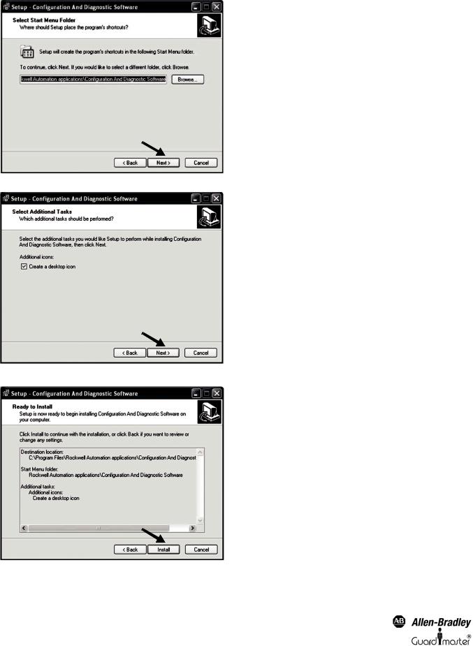
Figure 5: Select the start menu folder
Figure 6: Create desktop symbol
Figure 7: Run installation
6 |
Original instructions |
Light Curtain Multi-Function Control Module User Manual
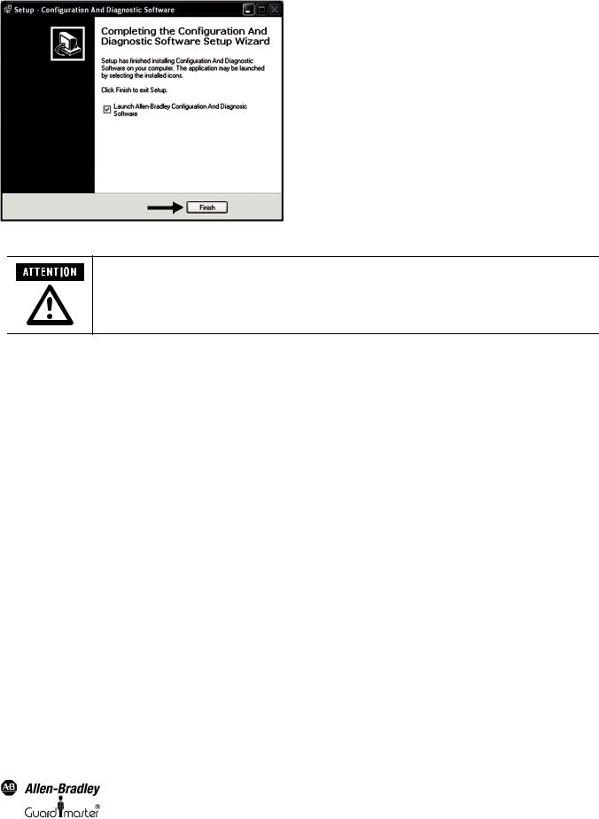
Figure 8: Installation finished
After installation, the authorized user is recommended to immediately enter their user registration information, as well as to change the password. The first time the program starts up, you will be automatically prompted to customize the password and user data. Access to the password, as well as the Optical Interface, must only be permitted for authorized personnel.
2.4. Installation USB driver for Optical Interface
The USB driver is installed automatically during the software installation.
Connect the USB Optical Interface to your computer. The drivers will be automatically loaded once the USB Optical interface is plugged into the available USB port.
2.5. Program start
The Configuration and Diagnostics Software can be started from the desktop icon or the windows start menu.
“Windows-Start” – “Programs” – “Rockwell Automation Applications” – “Configuration and Diagnostic Software” – “Configuration and Diagnostic
Software.”
In the Configuration and Diagnostic Software window (Figure 9), the following sub programs may be selected:
•GuardShield Safe 2/Safe 4 Safety Light Curtains
•MSR42 Safety Controller
The MSR42 Safety Controller sub program includes configuration and diagnostic functions for GuardShield Micro 400 safety light curtains.
Original instructions |
7 |
Light Curtain Multi-Function Control Module User Manual
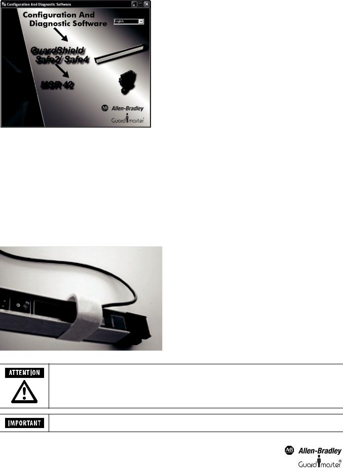
Figure 9: Selection window
First select your preferred language with the pull-down option “Language” in the top right corner of the window. Then select your preferred sub program and the safety warning window appears.
3. Optical Interface
The Optical Interface (Cat. Nr. 445L-AF6150) allows for a fast and easy communication between
•a GuardShield safety light curtain (Safe 2/Safe 4) and a PC or
•a safety controller module (MSR42) and a PC.
The Optical Interface can be used as a diagnosis tool (real time and long term diagnostics) in order to find errors such as insufficient supply voltage, a short circuit of the output, etc.
The Optical Interface can also be used for downand uploading configurations to a MSR42 controller. The MSR42 and Micro 400 features: blanking, muting, override (and more) may be selected according to customer specific applications and downloaded as described in chapter 5 on page 13.
Figure 10: Simple configuration with an Optical Interface
Access to the password, as well as the Optical Interface must only be permitted for authorized users.
Before connecting the USB Optical Interface to the computer the Configuration and Diagnostic Software has to be installed (See chapter 2.3 on page 4).
8 |
Original instructions |
Light Curtain Multi-Function Control Module User Manual
The connection is simple and completed in seconds:
•Plug the USB connector into an unused USB-port on your computer.
•Press the suction cup of the sensor head onto the marked position.  For a more secure connection, the suction cup may be dampened slightly.
•Interrupt the light curtain (if connected). The communication between the Rockwell device and your computer will be initiated.
4.Configuration Tool for GuardShield Safe 2/Safe 4 Light Curtains
4.1. Introduction
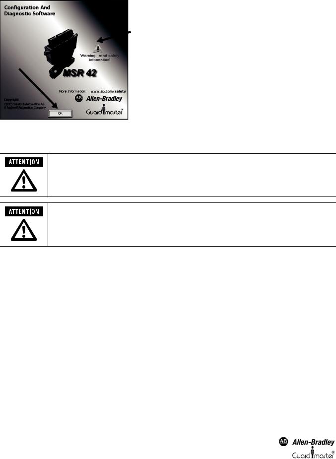
Select the “GuardShield Safe 2/Safe 4” light curtain icon in the selection window (Figure 9). A new window will appear (Figure 11) with a “warning: read safety information” symbol. Click on this symbol and read the safety warning. Thereafter click “OK” to continue.
Figure 11: GuardShield Safe 2/Safe 4 welcome screen
The “system designer” tab for Safe 2/Safe 4 screen will allow the user to select the light curtain to be used in the application.
Input base
Figure 12: “System Designer”
Original instructions |
9 |
Light Curtain Multi-Function Control Module User Manual
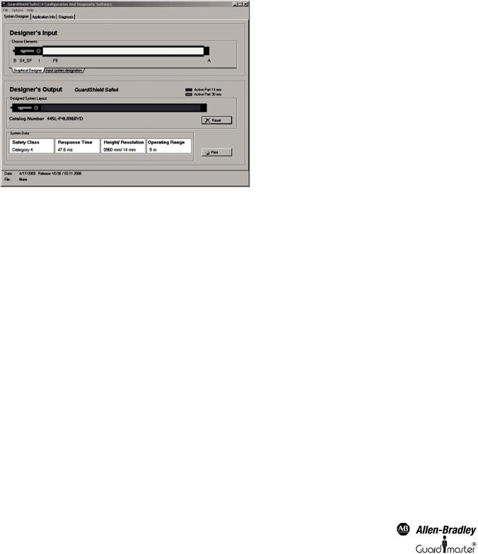
The “system designer” is split into two sections, a “Designer’s Input” and “Designer’s Output” section. The “Designer’s input” section is used to define a light curtain: pair or transmitter or receiver, as well as the protective field height and resolution. The “Designers Output” section displays the resulting information and catalog number for the configured light curtain.
To configure a light curtain stay in the Graphical Designer tab. Place the mouse cursor on each input base, press the left mouse button and a list will appear with all the available choices for that position.
Upon completion of the configuration selections, the light curtain catalog number, safety category, response time, height/resolution and operating range information will be displayed in the “Designer’s Output” section.
To design a new configuration, press the “Reset” button. To print the configuration, press the “Print” button.
Figure 13: Configured Safe 4 Light Curtain example
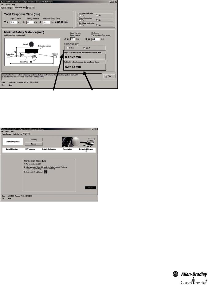
4.2. Safety Distance Calculator
Select the “Application Info” tab to display the minimal safety distance calculation section.
The display is usable for the GuardShield Safe 2/Safe 4 light curtains. For applications with the GuardShield Micro 400 Light Curtains, use the MSR42 safety controller sub program.
The “Application Info” is used to calculate the safety distances according to international standards. Results can be printed out and be implemented as part of the customers documentation package.
This display window calculates the safety distances for applications with vertical mounting according to the European standards DIN EN 13855-2010 and EN 61496-1, -2.
10 |
Original instructions |
Light Curtain Multi-Function Control Module User Manual
Response times |
|
Type of application |
|||||||||||
|
|
|
|
|
|
|
|
|
|
|
|
|
|
|
|
|
|
|
|
|
|
|
|
|
|
|
|
|
|
|
|
|
|
|
|
|
|
|
|
|
|
|
|
|
|
|
|
|
|
|
|
|
|
|
|
|
|
|
|
|
|
|
|
|
|
|
|
|
|
|
|
|
|
|
|
|
|
|
|
|
|
|
|
|
|
|
|
|
|
|
|
|
|
|
|
|
|
|
|
|
|
|
|
|
|
|
|
|
|
|
|
|
|
|
|
|
|
|
|
|
|
|
|
|
|
|
|
|
|
|
|
|
|
|
|
|
|
|
|
|
|
|
|
|
|
|
|
|
|
|
|
|
|
|
|
|
|
|
|
|
|
|
|
|
|
|
|
Safety category |
Light curtain parameter |
Figure 14: Safety distance calculator
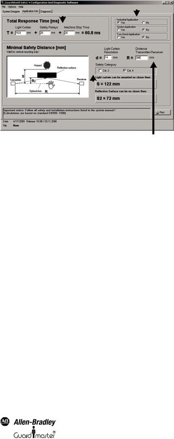
To calculate the minimal safety distance, first answer the three application questions below:
A“Industrial Application; Yes or No”
Choose “Yes” if the application is industrial. Select “No” if the application is not industrial (this means that children also have access to the application).
B“Stroke Application; Yes or No”
Choose “Yes” if the application starts automatically after a preset number of interruptions of the protective field occurs (e.g. presses). Select “No” if the application is not a stroke application.
C“Two Hand Application; Yes or No”
Choose “Yes” if the application is started with two hand control buttons. Choose “No” if not.
Then enter the response time information requested. This data will provide a total response time in milliseconds. Next enter the light curtain parameter data, and the safety category data.
Once all the data has been entered the window will display the minimal light curtain mounting distance and the minimal reflective surface distance data shown in Figure 15.
Original instructions |
11 |
Light Curtain Multi-Function Control Module User Manual
Distance between light |
Minimum reflective surface distance |
curtain pair |
|
Figure 15: Safety distance example
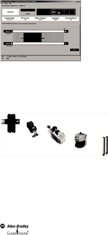
4.3. Safe 2/Safe 4 Diagnostics
Select the “diagnosis” tab in the Safe 2/Safe 4 configuration window.
Figure 16: “Diagnosis” tab
Connect the Optical Interface to your PC via the USB connector and attach the suction cup to the receiver of your Safe 2 or Safe 4 Light Curtain. The software establishes a communication after interrupting the protective field.
The software will detect the light curtain and monitor where the light curtain protective field is interrupted. The protective field viewer (Figure 17) displays the lowest and highest interrupted beams. Charting options are available to determine a pattern of which beams are interrupted vs. time (History tab).
In this example showing that beams 15 through 40 were interrupted by an object. As only the highest and lowest interrupted beam information is transmitted, nothing can be said with regards to the status of beams 16 to 39.
12 |
Original instructions |
Light Curtain Multi-Function Control Module User Manual
Figure 17: Safe 4 Diagnostics – Object blocking beams
The “History” tab will allow the interrupted beams to be charted versus time.
The “Service information” tab gives additional information for service / maintenance cases.
The “Object height” tab gives information with regards to the height of objects which have interrupted the light curtain.
5. Configuration Tool for MSR42
5.1. Introduction
The “MSR42” sub program of the Configuration and Diagnostic Software Tool is used to configure and diagnose MSR42 safety controllers as well as the connected GuardShield Micro 400 safety light curtain..
Figure 18: MSR42 can be configured to monitor various safety components
MSR42 safety controllers are supplied from the factory with a basic configuration. This basic configuration will satisfy the requirements of many typical GuardShield Micro 400 safety light curtains on/off applications with no configuration necessary. See the MSR42 user manual for more details. To satisfy more advanced applications the MSR42 Configuration tool and an Optical Interface make it easy for authorized personnel to configure the MSR42 for integrated operation with other safety devices such as E-Stops, safety interlocks, additional OSSD devices, or functions such as EDM, safety override, blanking or muting.
A customer specific configuration has to be downloaded to the MSR42 safety controller. It is carried out with the Optical Interface (See chapter 3 on page 8).
5.2. Starting MSR42 Configuration Tool
The Configuration Tool starts with the selection window (Figure 9). First select your preferred language with the pull-down option “language”. Then select the MSR42 icon and the welcome window for this product appears (Figure 19).
Original instructions |
13 |
Light Curtain Multi-Function Control Module User Manual
 2
2
1
Figure 19: “Welcome window” for MSR42.
A “Warning: read safety information” symbol is shown on this welcome window. Click on this warning symbol (2) and read this safety information. By clicking on the “OK” Button (1) you accept this safety information, and the program will start.
After installation, the authorized user is prompted to immediately enter their user registration information, as well as to change the password if desired. See Menu ‘Options’
Access to the password, as well as the Optical Interface must only be permitted for authorized users.
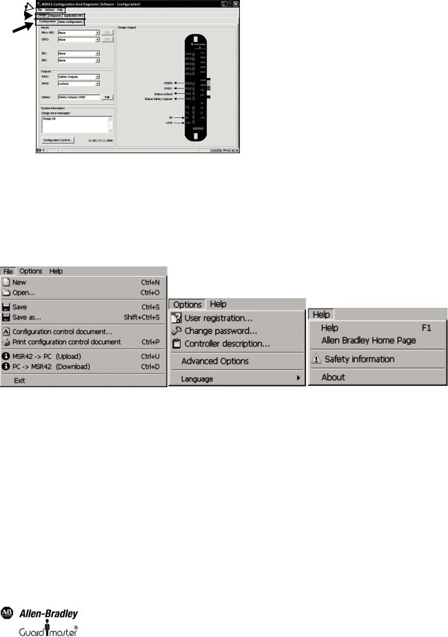
The MSR42 configuration window will appear (Figure 20). This window contains the menu bar (#1), as well as the following three main tabs (#2):
•Design
•Diagnosis
•Application Info
Each of these main tabs may be divided into further sub-tabs (#3).
14 |
Original instructions |
Light Curtain Multi-Function Control Module User Manual
1 

2 
3
Figure 20: Main window with menu bar (1) and main tabs (2) as well as sub-tabs (3)
5.3. The menu bar
The menu bar contains three pull-down menus:
1.File
2.Options
3.Help
Figure 21: Items in the Menu bar
5.3.1. Menu “File”
Menu “New”
Create a new configuration.
Menu “Open”
Opens an existing configuration file according to the given String and Data name. “*.cfg” is defined as the standard extension for the configuration data name.
Menu “Save”
Saves the current configuration under the most recent name and location.
Menu “Save as”
Saves the current configuration under a new name and given location.
Original instructions |
15 |
Light Curtain Multi-Function Control Module User Manual
Menu “Configuration control document”
Displays the current configuration control document on screen.
Menu “Print configuration control document”
Prints a Configuration Control Document with the current configuration.
Menu “MSR42 ÖPC (Upload)”
Uploads the current MSR42 control unit configuration into the PC (See chapter 5.5.4 on page 37).
Menu “PC ÖMSR42 (Download)”
Downloads the current configuration from the PC, into the MSR42 control unit (See chapter 5.5.1 on page 31).
Menu “Exit”
Ends the “MSR42 Configuration Tool” program.
5.3.2. Menu “Options”
5.3.2.1. Menu “User registration”
This menu button opens the “User registration” window (Figure 22). This information is required before a configuration download is allowed.
Data entered in the “User registration” fields will be used to complete the information printed on the Configuration control document (Figure 51). This information be only entered once, as it is saved in the PC.
Figure 22: User registration
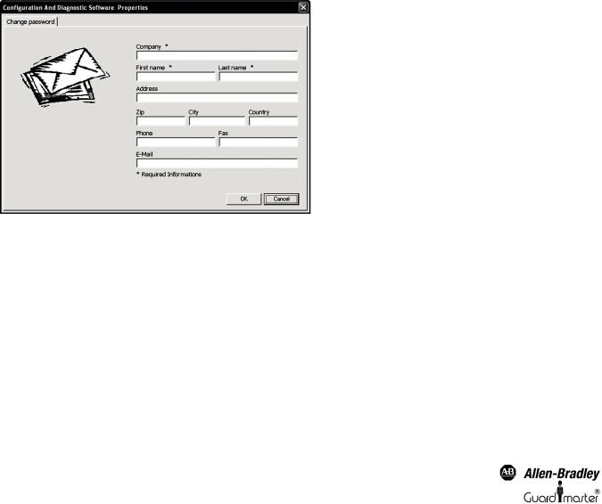
5.3.2.2. Menu “Change password”
This menu (Figure 23) allows the existing download “ABGM” (capital letters) password to be changed. The password as well as the Optical Interface should only be made available to authorized personnel who are permitted to change configurations. When installing the software, care should be taken to change the standard password “ABGM” (capital letters!) as soon as possible so that any possibility of unauthorized usage can be eliminated. A lost password can be recovered by contacting Rockwell Automation/Allen-Bradley Technical Support.
16 |
Original instructions |
Loading...