


 Loading...
RSLogix 5000
Fuzzy Designer
User Manual

Important User Information Solid state equipment has operational characteristics differing from those of electromechanical equipment. Safety Guidelines for the Application,
Installation and Maintenance of Solid State Controls (publication SGI-1.1 available from your local Rockwell Automation sales office or online at http://literature.rockwellautomation.com) describes some important differences between solid state equipment and hard-wired electromechanical devices. Because of this difference, and also because of the wide variety of uses for solid state equipment, all persons responsible for applying this equipment must satisfy themselves that each intended application of this equipment is acceptable.
In no event will Rockwell Automation, Inc. be responsible or liable for indirect or consequential damages resulting from the use or application of this equipment.
The examples and diagrams in this manual are included solely for illustrative purposes. Because of the many variables and requirements associated with any particular installation, Rockwell Automation, Inc. cannot assume responsibility or liability for actual use based on the examples and diagrams.
No patent liability is assumed by Rockwell Automation, Inc. with respect to use of information, circuits, equipment, or software described in this manual.
Reproduction of the contents of this manual, in whole or in part, without written permission of Rockwell Automation, Inc., is prohibited.
Throughout this manual, when necessary, we use notes to make you aware of safety considerations.
|
|
|
|
|
|
|
Identifies information about practices or circumstances that can cause |
|
WARNING |
||||||||
|
an explosion in a hazardous environment, which may lead to personal |
|||||||
|
|
|
|
|
|
|
||
|
|
|
|
|
|
|
injury or death, property damage, or economic loss. |
|
|
|
|
|
|
|
|
|
|
|
|
|
|
|
|
|
|
|
|
|
|
|
|
|
|
|
|
|
|
|
|
|
|
|
Identifies information that is critical for successful application and |
|
IMPORTANT |
|
|||||||
|
understanding of the product. |
|||||||
|
|
|
|
|
|
|
||
|
|
|
|
|
|
|
|
|
|
|
|
|
|
|
|
Identifies information about practices or circumstances that can lead |
|
ATTENTION |
|
|||||||
|
to personal injury or death, property damage, or economic loss. |
|||||||
|
|
|
|
|
|
|
||
|
|
|
|
|
|
|
Attentions help you identify a hazard, avoid a hazard, and recognize |
|
|
|
|
|
|
|
|
the consequence |
|
|
|
|
|
|
|
|
||
|
|
|
|
|
|
|
||
|
|
|
|
|
|
|
||
|
|
|
|
|
|
|
Labels may be on or inside the equipment, for example, a drive or |
|
SHOCK HAZARD |
|
|||||||
|
|
|
|
|
|
|
motor, to alert people that dangerous voltage may be present. |
|
|
|
|
|
|
||||
|
|
|
|
|
|
|
||
|
|
|
||||||
|
|
|
|
|
|
|
Labels may be on or inside the equipment, for example, a drive or |
|
BURN HAZARD |
|
|||||||
|
|
|
|
|
|
|
motor, to alert people that surfaces may reach dangerous |
|
|
|
|
|
|
|
|
||
|
|
|
|
|
|
|
temperatures. |
|
|
|
|
|
|
|
|
|
|
|
|
|
|
|
|
|
|
|
Allen-Bradley, ControlLogix, RSLogix 5000, Logix, and RSLinx are trademarks of Rockwell Automation, Inc. Trademarks not belonging to Rockwell Automation are property of their respective companies.

|
Table of Contents |
|
Preface |
About This Publication. . . . . . . . . . . . . . . . . . . . . . . . . . . . . |
7 |
|
Who Should Use This Publication. . . . . . . . . . . . . . . . . . . . . |
7 |
|
Conventions . . . . . . . . . . . . . . . . . . . . . . . . . . . . . . . . . . . . |
7 |
|
Chapter 1 |
|
Get Started with FuzzyDesigner |
Introduction . . . . . . . . . . . . . . . . . . . . . . . . . . . . . . . . . . . . |
9 |
|
Understanding FuzzyDesigner . . . . . . . . . . . . . . . . . . . . . . . |
9 |
|
Fuzzy Logic and Fuzzy Control Essentials . . . . . . . . . . . . |
12 |
|
Potential Use of Fuzzy Logic . . . . . . . . . . . . . . . . . . . . . . |
16 |
|
Specifications and Features . . . . . . . . . . . . . . . . . . . . . . . |
18 |
|
Integrated Design Environment (IDE) screen captures . . . . . . |
22 |
|
Chapter 2 |
|
FuzzyDesigner Component Library |
Introduction . . . . . . . . . . . . . . . . . . . . . . . . . . . . . . . . . . . . |
29 |
|
Component Interface . . . . . . . . . . . . . . . . . . . . . . . . . . . . . . |
29 |
|
Library of Components. . . . . . . . . . . . . . . . . . . . . . . . . . . . . |
30 |
|
Supported Membership Functions. . . . . . . . . . . . . . . . . . . . . |
30 |
|
Input Port . . . . . . . . . . . . . . . . . . . . . . . . . . . . . . . . . . . . . . |
32 |
|
User Defined Filter . . . . . . . . . . . . . . . . . . . . . . . . . . . . . |
33 |
|
Butterworth Low Pass Filter . . . . . . . . . . . . . . . . . . . . . . |
33 |
|
Connections . . . . . . . . . . . . . . . . . . . . . . . . . . . . . . . . . . |
33 |
|
Parameters . . . . . . . . . . . . . . . . . . . . . . . . . . . . . . . . . . . |
34 |
|
Input Linguistic Variable. . . . . . . . . . . . . . . . . . . . . . . . . . . . |
34 |
|
Connections . . . . . . . . . . . . . . . . . . . . . . . . . . . . . . . . . . |
36 |
|
Parameters . . . . . . . . . . . . . . . . . . . . . . . . . . . . . . . . . . . |
36 |
|
Output Linguistic Variable . . . . . . . . . . . . . . . . . . . . . . . . . . |
36 |
|
Defuzzification . . . . . . . . . . . . . . . . . . . . . . . . . . . . . . . . |
37 |
|
Connections . . . . . . . . . . . . . . . . . . . . . . . . . . . . . . . . . . |
42 |
|
Parameters . . . . . . . . . . . . . . . . . . . . . . . . . . . . . . . . . . . |
42 |
|
Output Takagi-Sugeno Variable . . . . . . . . . . . . . . . . . . . . . . |
42 |
|
Connections . . . . . . . . . . . . . . . . . . . . . . . . . . . . . . . . . . |
45 |
|
Parameters . . . . . . . . . . . . . . . . . . . . . . . . . . . . . . . . . . . |
46 |
|
Intermediate Linguistic Variable . . . . . . . . . . . . . . . . . . . . . . |
46 |
|
Connections . . . . . . . . . . . . . . . . . . . . . . . . . . . . . . . . . . |
47 |
|
Parameters . . . . . . . . . . . . . . . . . . . . . . . . . . . . . . . . . . . |
47 |
|
Rule Block. . . . . . . . . . . . . . . . . . . . . . . . . . . . . . . . . . . . . . |
47 |
|
Supported Format of Rules . . . . . . . . . . . . . . . . . . . . . . . |
48 |
|
Connections . . . . . . . . . . . . . . . . . . . . . . . . . . . . . . . . . . |
52 |
|
Parameters . . . . . . . . . . . . . . . . . . . . . . . . . . . . . . . . . . . |
52 |
|
PID Controller . . . . . . . . . . . . . . . . . . . . . . . . . . . . . . . . . . . |
52 |
|
Connections . . . . . . . . . . . . . . . . . . . . . . . . . . . . . . . . . . |
55 |
|
Parameters . . . . . . . . . . . . . . . . . . . . . . . . . . . . . . . . . . . |
56 |
|
Output Port . . . . . . . . . . . . . . . . . . . . . . . . . . . . . . . . . . . . . |
56 |
|
Connections . . . . . . . . . . . . . . . . . . . . . . . . . . . . . . . . . . |
56 |
|
Parameters . . . . . . . . . . . . . . . . . . . . . . . . . . . . . . . . . . . |
56 |

4
FuzzyDesigner Graphical User
Interface
FuzzyDesigner Projects
Chapter 3
Introduction. . . . . . . . . . . . . . . . . . . . . . . . . . . . . . . . . . . . 57
Setting Options . . . . . . . . . . . . . . . . . . . . . . . . . . . . . . . . . 57
Tool Bar. . . . . . . . . . . . . . . . . . . . . . . . . . . . . . . . . . . . 58
FuzzyDesigner Control Basics. . . . . . . . . . . . . . . . . . . . . . . 59
Main Menu . . . . . . . . . . . . . . . . . . . . . . . . . . . . . . . . . . . . 60
Chapter 4
Introduction. . . . . . . . . . . . . . . . . . . . . . . . . . . . . . . . . . . . 67 Working with Projects . . . . . . . . . . . . . . . . . . . . . . . . . . . . 67 Creating a Project . . . . . . . . . . . . . . . . . . . . . . . . . . . . . 69 Opening an Existing Project . . . . . . . . . . . . . . . . . . . . . 69 Changing the Active Project . . . . . . . . . . . . . . . . . . . . . 70 Project Information . . . . . . . . . . . . . . . . . . . . . . . . . . . . 70 Saving a Project . . . . . . . . . . . . . . . . . . . . . . . . . . . . . . 71 Closing a Project. . . . . . . . . . . . . . . . . . . . . . . . . . . . . . 71 Designing a Project. . . . . . . . . . . . . . . . . . . . . . . . . . . . 72 Printing a Project . . . . . . . . . . . . . . . . . . . . . . . . . . . . . 72 Designing a Fuzzy System . . . . . . . . . . . . . . . . . . . . . . . . . 72 Fuzzy System Project Window. . . . . . . . . . . . . . . . . . . . 73 Working with Blocks . . . . . . . . . . . . . . . . . . . . . . . . . . 73 Working with Text . . . . . . . . . . . . . . . . . . . . . . . . . . . . 75 Fuzzy System Components . . . . . . . . . . . . . . . . . . . . . . . . . 75 Input Port. . . . . . . . . . . . . . . . . . . . . . . . . . . . . . . . . . . 76 Input Linguistic Variable . . . . . . . . . . . . . . . . . . . . . . . . 79 Output Port . . . . . . . . . . . . . . . . . . . . . . . . . . . . . . . . . 82 Output Linguistic Variable . . . . . . . . . . . . . . . . . . . . . . . 84 Output Takagi-Sugeno Variable . . . . . . . . . . . . . . . . . . . 88 Intermediate Linguistic Variable. . . . . . . . . . . . . . . . . . . 92 Rule Block . . . . . . . . . . . . . . . . . . . . . . . . . . . . . . . . . . 94 PID Controller . . . . . . . . . . . . . . . . . . . . . . . . . . . . . . . 97 Term Editor . . . . . . . . . . . . . . . . . . . . . . . . . . . . . . . . . . . . 102 Term Properties Dialog . . . . . . . . . . . . . . . . . . . . . . . . . . . 105 Rule Editor . . . . . . . . . . . . . . . . . . . . . . . . . . . . . . . . . . . . 108 Operations with Rules. . . . . . . . . . . . . . . . . . . . . . . . . . 109 Rule Editor Tool Bar . . . . . . . . . . . . . . . . . . . . . . . . . . . 110 Port Order Editor . . . . . . . . . . . . . . . . . . . . . . . . . . . . . . . . 113 Watch . . . . . . . . . . . . . . . . . . . . . . . . . . . . . . . . . . . . . . . . 113 History Graph . . . . . . . . . . . . . . . . . . . . . . . . . . . . . . . . . . 117 History Graph Control – Context Menu . . . . . . . . . . . . . 119 History Graph Control – Tool Bar . . . . . . . . . . . . . . . . . 121 History Graph Control – Mouse Dragging . . . . . . . . . . . 122 2D Graph . . . . . . . . . . . . . . . . . . . . . . . . . . . . . . . . . . . . . 122 2D Graph Control – Context Menu . . . . . . . . . . . . . . . . 124 2D Graph Control – Tool Bar . . . . . . . . . . . . . . . . . . . . 125 3D Graph . . . . . . . . . . . . . . . . . . . . . . . . . . . . . . . . . . . . . 125 3D Graph Control – Context Menu . . . . . . . . . . . . . . . . 128

5
3D Graph Control – Tool Bar . . . . . . . . . . . . . . . . . . . . 130
3D Graph Control – Mouse Dragging . . . . . . . . . . . . . . 130
|
Chapter 5 |
|
Fuzzy System Simulation |
Introduction . . . . . . . . . . . . . . . . . . . . . . . . . . . . . . . . . . . |
131 |
|
Chapter 6 |
|
RSLogix 5000 Add-On Instruction |
Introduction . . . . . . . . . . . . . . . . . . . . . . . . . . . . . . . . . . . |
133 |
|
Generating a Fuzzy Add-On Instruction . . . . . . . . . . . . . . . |
134 |
|
Add-On Instruction Parameters . . . . . . . . . . . . . . . . . . . |
135 |
|
Importing Add-On Instructions to RSLogix 5000 Projects . . . |
136 |
|
Monitoring and Updating a Project Online . . . . . . . . . . . . . |
138 |
|
Configuring RSLinx OPC Server Topic. . . . . . . . . . . . . . . . . |
144 |
|
Modifying Fuzzy System Parameters Online . . . . . . . . . . . . |
145 |
|
Importing an Add-On Instruction to FuzzyDesigner. . . . . . . |
146 |
|
Chapter 7 |
|
XML Format of a Fuzzy Project |
Prolog . . . . . . . . . . . . . . . . . . . . . . . . . . . . . . . . . . . . . . . . |
147 |
|
Document Element . . . . . . . . . . . . . . . . . . . . . . . . . . . . . . |
147 |
|
Chapter 8 |
|
Glossary |
Introduction . . . . . . . . . . . . . . . . . . . . . . . . . . . . . . . . . . . |
149 |

6

Preface
About This Publication
Who Should Use This
Publication
Conventions
Use this manual to understand how to best use the features in RSLogix 5000 software version 16, FuzzyDesigner.
This manual describes the necessary tasks to:
•build fuzzy systems as block diagrams from components of the FuzzyDesigner Component Library and use FuzzyDesigner functions to complete the project.
•use, execute, and monitor the designed fuzzy system on Rockwell Automation Logix5000 controllers.
•understand the fuzzy project, and how you can export it to the XML format.
This manual is for application and control engineers, to enhance functionality of control and decision making systems.
Text that is |
Identifies |
|
|
Bold |
A value that you must enter exactly as shown |
|
|
Italic |
A variable that you replace with your own text or value |
|
|
Courier |
Example programming code, shown in a monospace font so |
|
you can identify each character and space |
|
|
Enclosed in brackets |
A keyboard key |
|
|
Publication LOGIX-UM004A-EN-P - March 2007

8 Preface
Notes:
Publication LOGIX-UM004A-EN-P - March 2007

Chapter 1
Introduction
Understanding
FuzzyDesigner
Get Started with FuzzyDesigner
Topic |
Page |
|
|
Understanding FuzzyDesigner |
9 |
|
|
Fuzzy Logic and Fuzzy Control Essentials |
12 |
|
|
Specifications and Features |
18 |
|
|
FuzzyDesigner is a software package for designing a fuzzy system to be implemented as a Hierarchical Fuzzy System (HFS). Fuzzy systems can be used in the following applications:
•Industrial automation and control systems
•Process diagnostics and intelligent monitoring systems
•Artificial intelligence
•Decision-making and forecasting
Hierarchical Fuzzy System
FuzzyDesigner enables application and control engineers to enhance the functionality of control and decision making systems in various branches of industry.
FuzzyDesigner includes a library of components you can use to design a fuzzy system that includes nonlinear input-output mapping. You can use a hierarchical structure to decompose a complex fuzzy system into smaller and simpler parts. This reduces the internal complexity of a fuzzy model and results in fewer fuzzy rules and provides easier insight into the system operation.
Publication LOGIX-UM004A-EN-P - March 2007
10 Get Started with FuzzyDesigner
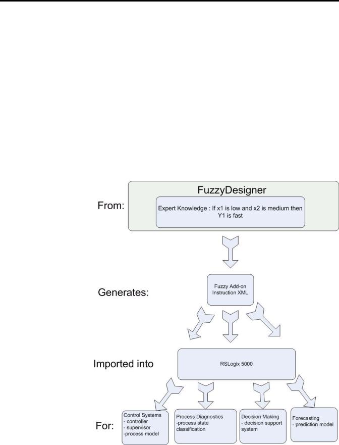
FuzzyDesigner is designed to work with Rockwell Automation's Logix5000 family of controllers. A fuzzy system designed in FuzzyDesigner can be exported to an L5X Add-On instruction (AOI) format. You can then import the fuzzy AOI into any of your projects as needed. Fuzzy AOIs can be used by any of the programming languages (Function Block Diagram, Ladder Logic, or Structured Text). With FuzzyDesigner, you can also monitor and update the selected fuzzy AOI online, directly in the running controller. This is made available through the RSLinx OPC Server.
The Intended Use of FuzzyDesigner figure shows the underlying idea and intended use of the FuzzyDesigner software package used in designing Fuzzy Add-On Instructions for Logix applications. You can build smart components, based on the expert knowledge encoded in fuzzy If-Then rules. You can use these components in the many applications listed above.
Intended Use of FuzzyDesigner
Publication LOGIX-UM004A-EN-P - March 2007
Get Started with FuzzyDesigner |
11 |
|
|
A Fuzzy Add-On instruction does not typically compete against standard controls found in Proportional-Integral-Derivative Controllers (PID). Fuzzy logic is a complementary tool, and fills functional gaps not addressed in standard controllers such as PIDs or Model Predictive Controllers.
A development cycle of fuzzy logic solutions for Logix applications consists of multiple steps.
1. |
Design the fuzzy system in FuzzyDesigner. |
2. |
Generate the fuzzy Add-On Instruction. |
3. |
Integrate (import and instantiate) the fuzzy AOI to your RSLogix |
|
5000 project. |
4. |
Monitor and tune the fuzzy AOI running in Logix online by |
|
using FuzzyDesigner. |
Using FuzzyDesigner with RSLogix 5000 Software |
|
n |
p |
o
q
If you are unfamiliar with fuzzy logic, the next section introduces fuzzy logic terms and principles you might use in your fuzzy system.
Publication LOGIX-UM004A-EN-P - March 2007
12 Get Started with FuzzyDesigner
Fuzzy Logic and Fuzzy Control Essentials
This section introduces basic concepts used in a Fuzzy Add-On Instruction. The designer should know how to deal with an instruction’s inputs, outputs, and fuzzy If-Then rules that will be used to define input-output mapping.
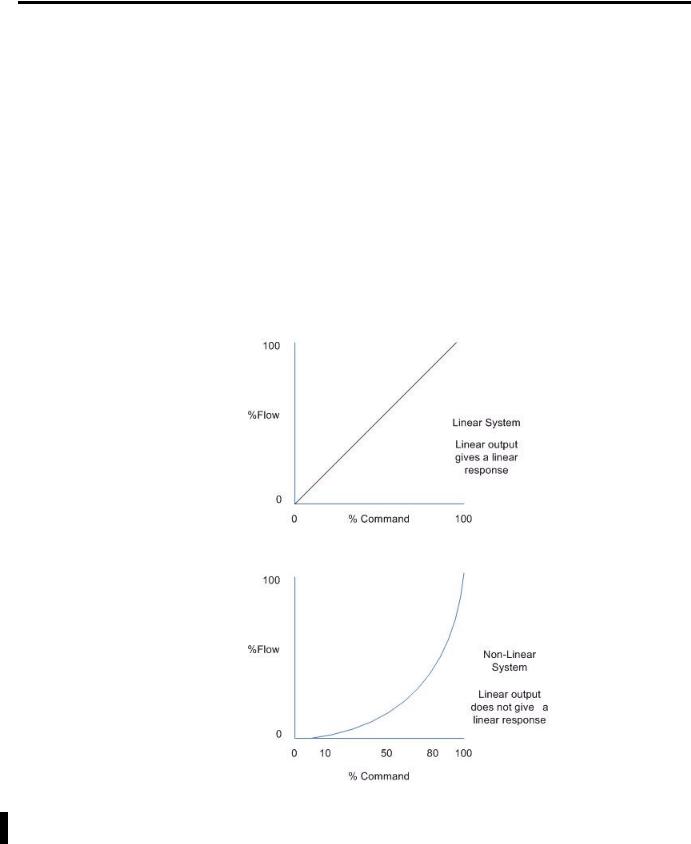
There are quite a number of systems or processes that are highly nonlinear, not well understood from the formal description point of view, or for which a mathematical model is not readily available. For these systems or processes, there is often an expert that is capable of supervising or controlling the process in a satisfactory manner. The figure Nonlinear System Example illustrates the difference between linear and nonlinear systems.
Nonlinear System Example
The decision making the expert uses in control system supervision can be expressed as a set of Fuzzy Logic If-Then rules.
Publication LOGIX-UM004A-EN-P - March 2007

Get Started with FuzzyDesigner |
13 |
|
|
An expert may be an operator, a maintenance person, or a control engineer, who knows what adjustments are needed during process instability. These adjustments may include defining setpoints for process variables, defining control action in feedforward or feedback contro,l or setting gains of conventional controllers, and may be as simple as turning a valve or knob.
Rockwell Automation is introducing a tool for building smart instructions that encode If-Then rules and use fuzzy logic internally to describe vague and incomplete knowledge in a natural way. Fuzzy Logic may serve in situations where:
•the process has not been automated and is running in Manual mode.
•a well-tuned PID controller does not provide the desired response, however, the expert knowledge is available to define the rules for a fuzzy algorithm.
Let’s look at an example where we will discuss building a Heat, Ventilation and Air Conditioning (HVAC) system that manipulates the compressor speed based on room temperature and humidity. In HVAC systems, room comfort is often associated with vague (fuzzy) values of temperature and humidity that are more suitable for describing the problem than numerical (crisp) values.
Fuzzy rules used in this example might be as follows.
If |
Then |
|
|
Temperature is high and humidity is |
Speed is medium |
high |
|
|
|
Temperature is medium and humidity |
Speed is high |
is very high |
|
|
|
Consider these factors when developing fuzzy rules:
•How do I specify High and other fuzzy values in fuzzy rules?
•How do the rules process numerical inputs provided by tags associated with sensors?
•How do the rules derive outputs from inputs?
•If the output generated is vague (fuzzy), how do I get the numerical (crisp) value at the output when needed?
Publication LOGIX-UM004A-EN-P - March 2007
14 Get Started with FuzzyDesigner
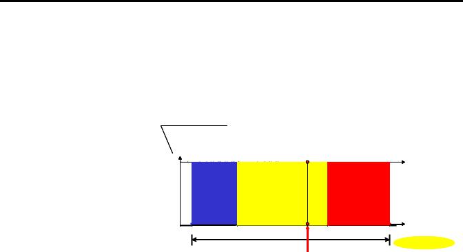
Crisp and Fuzzy
For temperature readings, you can classify a reading into three sets, Low, Medium and High. Each set contains values in a given interval, and the intervals do not overlap. This means that a single reading or value is uniquely classified into one set.
degree of membership (level of classification)
|
|
|
Classification |
Low |
Medium |
High |
Result |
|
|||
1 |
|
|
1.00 Medium |
0 |
|
|
0.0 High |
range |
|
0.0 Low |
|
|
|
temperature |
|
20 |
|
150 |
|
Crisp Value |
|
||
|
|
|
|
Degree of membership (DOM) is a value describing how well |
|
TIP |
||
the particular value of the variable (in this case, temperature) |
||
|
||
|
||
|
fits the meaning of the label of the set, Medium. If the DOM is |
|
|
1, the current temperature is understood as 100% Medium. |
However, vague classifications are more realistic as there is usually no sharp border between Low, Medium, or High temperatures. In this situation, however, a single numerical value might fall into multiple categories. For example, it might be partially Medium, and partially High as shown in the following figure. A specification of how much the particular value of temperature fits into the meaning of the label of the category (fuzzy set) is described by the membership function, which becomes a design parameter of the fuzzy controller.
Publication LOGIX-UM004A-EN-P - March 2007

Get Started with FuzzyDesigner |
15 |
|
|
Similar fuzzy terms are designed for the output variables, that is, Low,
Medium, and High for compressor speed in our example.
Fuzzy rules
The way in which the classified inputs are treated when passing through rules is shown in the following figure for our compressor control example.
Publication LOGIX-UM004A-EN-P - March 2007

16 Get Started with FuzzyDesigner
First, the numerical values of Temperature and Humidity get their meaning. In our case, the current setting of the Temperature is such that it is both 85% Medium and 40% High. Humidity is both 80% High and 50% Very High. The first rule is thus 80% true for the current inputs while the second rule is 40% true when using minimum for the and operation. The first rule states that, if 100% satisfied, the compressor should run at Medium speed. Currently, the first rule is only 80% fulfilled, so one method of how to consider that the rule is only 80% fulfilled is to truncate the Medium fuzzy set for the output at the level 0.8.
A similar situation happens with the second rule where High compressor speed is only 40% fulfilled. As both rules are used at the same time, their conclusions must be combined to get a fuzzy value for the output, which is compressor speed. The partially-fulfilled Medium and High fuzzy sets are unified, and a single fuzzy value is assigned to Compressor Speed. As conventional control systems cannot deal with fuzzy values, the fuzzy instruction includes conversion from a fuzzy to a crisp value. For this case, the center of gravity for the green area is computed and used to represent the original fuzzy value.
To summarize, the designer has to:
•define input and output variables.
•cover the interval of the respective variable by fuzzy sets (that is, membership functions).
•write if-then rules using labels of the fuzzy sets defined previously.
Potential Use of Fuzzy Logic
FuzzyDesigner enables you to enhance the functionality of existing or new control and decision making systems in various branches of industry.
The fuzzy system designed and generated by FuzzyDesigner can be used in control systems, for example, as a direct nonlinear fuzzy-rule based controller, PID-feedback control system supervisor, or a process model in a Model Predictive Control scheme. Input and output filters are used for signal preprocessing such as filtering, deriving trends, and many other functions that might add dynamics to the static I/O map generated from fuzzy rules. Input filters can also be designed in FuzzyDesigner. Output filtering is an option and contains, for instance, a discrete integrator fed by the output of the Fuzzy Add-On Instruction.
Publication LOGIX-UM004A-EN-P - March 2007

Get Started with FuzzyDesigner |
17 |
|
|
Nonlinear, Fuzzy Rule Based Supervisor of a PID Controller
|
|
Plant States |
|
|
FUZZY |
feedforward |
|
|
FUZZY |
|
|
|
SUPERVISOR |
|
|
|
SUPERVISOR |
|
|
|
PID |
|
|
|
gains |
CV |
|
SP |
PID |
||
PLANT |
|||
|
PID |
||
|
CONTROLLER |
PLANT |
|
|
CONTROLLER |
|
PV
The great advantage of fuzzy supervision is that it can be applied to existing control and there is little danger of making errors in design. Most frequently used is a supervised PID controller where PID gains, feedforward action, or setpoints are being modified dynamically by rules depending on the process status and external conditions defined through setpoints.
Smart Switching Between Conventional Controllers, Takagi-Sugeno Controller
|
FUZZY SUPERVISOR |
Plant State |
|
FUZZY SUPERVISOR |
|
|
|
|
Schedule weights [0,1]
|
CONTROLLER |
× |
|
|
|
1 |
|
|
|
|
CONTROLLER |
|
|
|
|
1 |
|
|
+ CV |
Setpoints |
CONTROLLER |
|
|
|
|
|
PLANT |
||
|
CONTROLLER |
× |
|
|
|
2 |
+ |
PLANT |
|
|
2 |
|
+ |
|
|
CONTROLLER |
|
|
|
|
|
|
|
|
|
CONTROLLER |
|
× |
|
|
3 |
|
|
|
|
3 |
|
|
|
Process Variables
Another popular control structure with fuzzy logic is smart switching between local controllers. A local controller is an analytical controller designed to work around specific process operation conditions. Once the conditions change, the rule based supervisor decreases the influence of one controller and gives more weight to another controller that has been designed to work in the new conditions.
Publication LOGIX-UM004A-EN-P - March 2007
18 Get Started with FuzzyDesigner
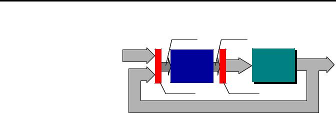
Feedback Control System with Direct Fuzzy Controller
Control system status |
Primary controls |
|
Setpoints |
|
|
FUZZY |
Control |
PLANT |
CONTROLLER |
Variables |
PLANT |
|
||
Input filter |
Output filter |
|
Process Variables |
|
|
A fuzzy controller with the above structure typically handles multiple inputs and generates multiple outputs. This system is recommended for experienced designers since control variables are direct functions of rules. The number of rules increases rapidly with the number of inputs and fuzzy terms for inputs. The problem of dimensionality can, however, be reduced by hierarchical structuring of the rule base of the controller, which is supported by FuzzyDesigner.
Specifications and Features
FuzzyDesigner features and specifications are summarized in the following tables.
For details, refer to the subsequent chapters.
Fuzzy System Components
Components are graphical objects, blocks you work with, to design a fuzzy system.
Component |
Membership |
AND |
OR |
Aggregation |
Inference |
Defuzzification |
|
functions |
|
|
|
(Activation) |
|
|
|
|
|
|
|
|
|
Type/method if applicable |
|
|
|
|
|
|
|
|
|
|
|
|
Input Port |
|
|
|
|
|
|
|
|
|
|
|
|
|
Input Linguistic |
Trapezoidal, |
|
|
|
|
|
Variable |
S-shape, and their |
|
|
|
|
|
|
inverses |
|
|
|
|
|
|
|
|
|
|
|
|
Rule Block |
|
Min/product |
Max |
|
|
|
|
|
t-norms |
|
|
|
|
|
|
|
|
|
|
|
Output |
Trapezoidal, |
|
|
Max s-norm |
Mamdani/ Fuzzy |
CA/MCA/ |
Linguistic |
singleton |
|
|
|
Arithmetic |
MOM/SOM/ LOM |
Variable |
|
|
|
|
|
|
|
|
|
|
|
|
|
Output Port |
|
|
|
|
|
|
|
|
|
|
|
|
|
Publication LOGIX-UM004A-EN-P - March 2007
Get Started with FuzzyDesigner |
19 |
|
|
Component |
Membership |
AND |
OR |
Aggregation |
Inference |
Defuzzification |
|
functions |
|
|
|
(Activation) |
|
|
|
|
|
|
|
|
|
Type/method if applicable |
|
|
|
|
|
|
|
|
|
|
|
|
Intermediate |
|
|
|
Max s-norm |
|
|
Linguistic |
|
|
|
|
|
|
Variable |
|
|
|
|
|
|
|
|
|
|
|
|
|
Output T-S |
|
|
|
Max s-norm |
|
|
Variable |
|
|
|
|
|
|
|
|
|
|
|
|
|
PID Controller |
|
|
|
|
|
|
|
|
|
|
|
|
|
Fuzzy System Analysis Tools
Tool |
Description |
|
|
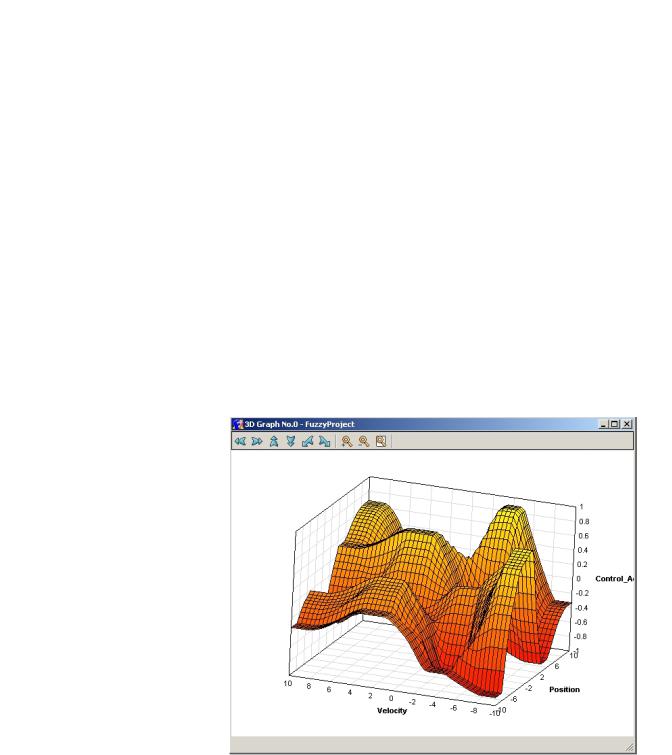
2D/3D mesh plots |
Visualization of input-output static mappings generated |
|
by the fuzzy system or its specified subsystem |
|
|
Interactive plot control |
Color, grid, texture, zoom, and viewpoint management |
|
|
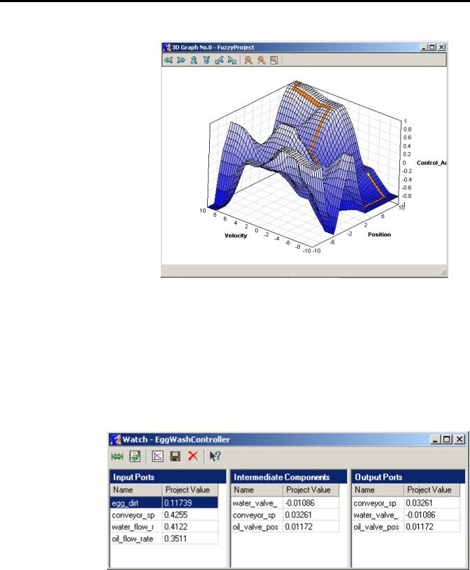
Tracing fuzzy system evaluation |
Marks output on the mesh when input is being changed |
|
|
FuzzyDesigner Mesh Plot
Publication LOGIX-UM004A-EN-P - March 2007
20 Get Started with FuzzyDesigner
FuzzyDesigner Mesh Plot with Simulated Path
Fuzzy System Monitoring
Feature |
Description |
|
|
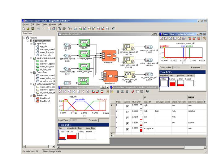
Numerical and graphical display |
Monitoring of all internal variables |
|
|
Archiving |
Recording specified internal or external variables |
|
|
History graph |
Plotting history graph for on-line or off-line monitoring |
|
|
Fuzzy System Monitoring Through Numerical Displays
Publication LOGIX-UM004A-EN-P - March 2007
Get Started with FuzzyDesigner |
21 |
|
|
Fuzzy System Monitoring Through Plotting Historical Recordings and On-Line
Update
FuzzyDesigner Project Formats
File Format |
Description |
|
|
XML |
.FSP – complete project file generated by |
|
FuzzyDesigner, .XML – user-supplied fuzzy system or |
|
project file |
|
|
Publication LOGIX-UM004A-EN-P - March 2007

22 Get Started with FuzzyDesigner
|
Direct Support of Logix5000 controllers |
|
|
FuzzyDesigner, version 16.00 and later, supports Rockwell |
|
|
Automation's Logix5000 family of controllers. The fuzzy system |
|
|
designed using FuzzyDesigner can be exported to an RSLogix 5000 |
|
|
Add-On Instruction (AOI) XML import file. You can then import the |
|
|
fuzzy system into any of your projects as needed. Fuzzy AOI can be |
|
|
used by any of the programming languages (Function Block Diagram, |
|
|
Ladder Logic, or Structured Text). With FuzzyDesigner, you can also |
|
|
monitor and update the selected fuzzy AOI online, directly in the |
|
|
running controller. This is made available through RSLinx OPC Server. |
|
|
|
|
Features |
Description |
|
|
|
|
Export fuzzy AOI |
Utility for export of designed fuzzy system into L5X file. |
|
|
|
|
On-line parameter change |
Changing parameters of a fuzzy system downloaded to the controller |
|
|
dynamically is enabled. |
|
|
|
|
Real-time fuzzy system monitoring |
Exact copy of the fuzzy system running on the PLC allows FuzzyDesigner to |
|
|
monitor all internal variables on the computer when both copies are fed with |
|
|
the identical inputs. |
|
|
|
|
Integrated Design Environment (IDE) screen captures
Some of the FuzzyDesigner features, summarized in the preceding tables, are shown in this section.
Publication LOGIX-UM004A-EN-P - March 2007
Get Started with FuzzyDesigner |
23 |
|
|
FuzzyDesigner Environment in Brief
Publication LOGIX-UM004A-EN-P - March 2007
24 Get Started with FuzzyDesigner
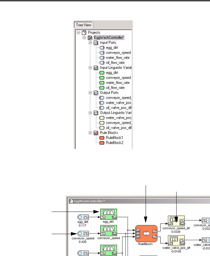
Project Tree view
FuzzyDesigner Environment - Component examples
Rule Block |
Output Liguistics |
|
Variable |
Input Linguistics
Variable
Input Port
Publication LOGIX-UM004A-EN-P - March 2007

Get Started with FuzzyDesigner |
25 |
|
|
FuzzyDesigner Membership Functions
Term Editor
Degree of Fulfillment window
FuzzyDesigner Rule Base - Rule Editor
Publication LOGIX-UM004A-EN-P - March 2007

26 Get Started with FuzzyDesigner
FuzzyDesigner Rule Interfacing
|
|
|
|
FuzzyDesigner Defuzzification Methods |
||||
DOF(negative) |
|
|
|
|
|
|
|
|
|
|
|
|
|
DOF(negative) is maximal |
|||
|
|
|
|
DOF(zero) |
|
|
||
|
|
|
|
|
|
|
|
|
|
|
|
|
|
|
|
|
|
|
y* |
y* |
|
|
|
|
||
|
|
y* y* y* |
|
|||||
|
(MCA) |
(CA) |
|
(SOM) (MOM) (LOM) |
|
|||
Publication LOGIX-UM004A-EN-P - March 2007

Get Started with FuzzyDesigner |
27 |
|
|
FuzzyDesigner PID Controller
Publication LOGIX-UM004A-EN-P - March 2007

28 Get Started with FuzzyDesigner
Notes:
Publication LOGIX-UM004A-EN-P - March 2007
Chapter 2
FuzzyDesigner Component Library
Introduction
The FuzzyDesigner Component Library offers eight components from which you can efficiently build distributed fuzzy systems.
Topic |
Page |
|
|
Component Interface |
29 |
|
|
Library of Components |
30 |
|
|
Supported Membership Functions |
30 |
|
|
Input Port |
32 |
|
|
Input Linguistic Variable |
34 |
|
|
Output Linguistic Variable |
36 |
|
|
Output Takagi-Sugeno Variable |
42 |
|
|
Intermediate Linguistic Variable |
46 |
|
|
Rule Block |
47 |
|
|
PID Controller |
52 |
|
|
Output Port |
56 |
|
|
Component Interface
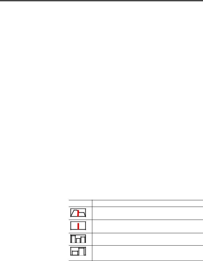
The connection between components is called a link. Generally, a Hierarchical Fuzzy System (HFS) computes with data in the form of a crisp (real) value and/or a fuzzy set. Not all components enable both types of data to be transferred over the link. The data type on both ends of a link should match. FuzzyDesigner uses icons to define a link type as follows.
FuzzyDesigner Icons
Icon Description
Crisp value (input or output value link) – input crisp values and crisp values resulting from defuzzification are transferred over the link
Crisp value (input or output value link) – crisp values are transferred over the link
DOF value (input or output logical link) – degrees of fulfillment of fuzzy terms of a fuzzy variable are transferred over the link to a rule block
DOF value (input or output logical link) – degrees of fulfillment of fuzzy terms resulting from rule block evaluation are transferred over the link to a fuzzy variable
Publication LOGIX-UM004A-EN-P - March 2007
30 FuzzyDesigner Component Library
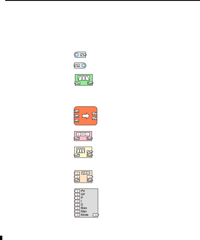
Library of Components
The FuzzyDesigner Component Library offers the following components from which you can assemble fuzzy systems ranging from single input – single output systems to multiple input – multiple output systems with complex hierarchical structure of rules.
FuzzyDesinger Component Library Icons
Icon |
Name |
Description |
|
|
|
|
Input Port |
Preprocesses and stores values of a fuzzy |
|
|
system’s input variables. |
|
|
|
|
Output Port |
Stores values of a fuzzy system’s output |
|
|
variables. |
|
|
|
|
Input Linguistic |
Stores linguistic terms and is used for |
|
Variable |
classification of the actual component input, |
|
|
represented by a crisp value, into the fuzzy sets |
|
|
defined for the respective linguistic terms. In |
|
|
fuzzy control, the process where the input is |
|
|
converted from a crisp value is commonly called |
|
|
fuzzification. |
|
|
|
|
Rule Block |
Stores rules and computes degree of fulfillment |
|
|
of rule conditions . |
|
|
|
|
Intermediate |
Bridges logical chaining of rule blocks. |
|
Linguistic |
|
|
Variable |
|
|
|
|
|
Output Linguistic |
Stores linguistic terms and computes the output |
|
Variable |
value from degrees of fulfillment of stored terms |
|
|
(defuzzification). It implements the process of |
|
|
activation of output linguistic terms defined as |
|
|
fuzzy sets. |
|
|
|
|
Output |
Stores parameters of functional terms and |
|
Takagi-Sugeno |
computes the output value from degrees of |
|
Variable |
fulfillment of terms. |
|
|
|
|
PID Controller |
Allows intelligent supervision of a built-in PID |
|
|
controller. |
|
|
|
Supported Membership
Functions
Library blocks let you work with fuzzy sets as defined by membership functions. Let x be the linguistic variable and A(x) be the degree of membership of x to the fuzzy set A defined by the sketched membership function. FuzzyDesigner works with the following types of membership functions.
Publication LOGIX-UM004A-EN-P - March 2007
Loading...