


1N5819
1N5817 - 1N5819
Features
• 1.0 ampere operation at T
with no thermal runaway.
• For use in low voltage, high
frequency inverters free
wheeling, and polarity
protection applications.
1.0 Ampere Schottky Barrier Rectifiers
= 90°C
A
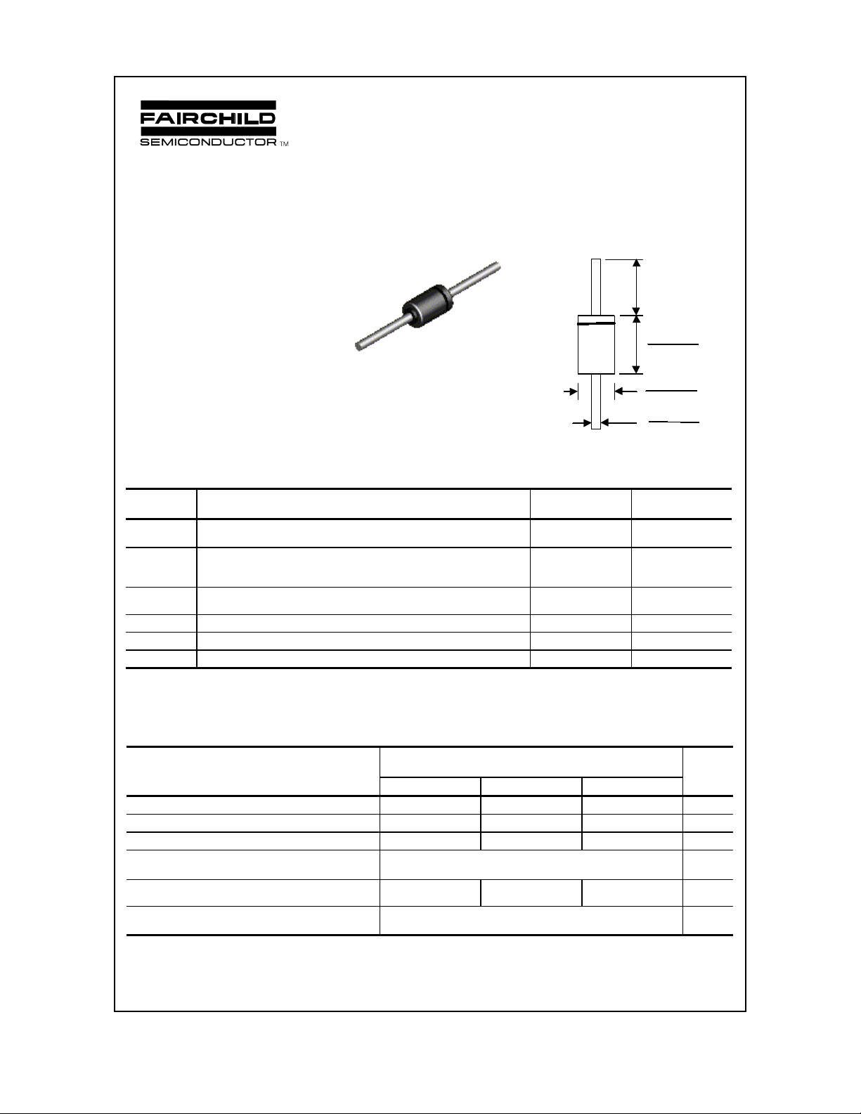
COLOR BAND DENOTES CATHODE
DO-41
Discrete POWER & Signal
Technologies
1.0 min (25.4)
Dimens i o ns in
inches (mm)
0.205 (5.21)
0.160 (4.06)
0.107 (2.72)
0.080 (2.03)
0.034 (0.86)
0.028 (0.71)
1N5817-1N5819
Absolute Maximum Ratings* T
= 25°C unless otherwise noted
A
Symbol Parameter Value Units
I
O
i
f(surge)
P
D
R
θ
JA
T
stg
T
J
Average Rectified Current
.375 " lead length @ T
= 90°C
A
Peak Forward Surge Current
8.3 ms single half-sine-wave
Superimposed on rated load (JEDEC method)
Total Device Dissipation
Derate above 25°C
Thermal Resistance, Junction to Ambient 80
Storage Temperature Range -65 to +125
Operating Junction Temperature -65 to +125
1.0 A
25 A
1.25
12.5
mW/°C
°
C/W
W
°
C
°
C
*These ratings are limiting values above which the serviceability of any semiconductor device may be impaired.
Electrical Characteristics T
= 25°C unless otherwise noted
A
Parameter Device Units
1N5817 1N5818 1N5819
Peak Repetitive Reverse Voltage 20 30 40 V
Maximum RMS Voltage 14 21 28 V
DC Reverse Voltage (Rated VR)
Maximum Reverse Current TA = 25°C
@ rated V
R
TA = 100°C
Maximum Forward Voltage @ 1.0 A
@ 3.0 A
Typical Junction Capacitanc e
V
= 4.0 V, f = 1.0 MHz
R
20 30 40 V
0.5
10
450
750
550
875
600
900
110 pF
mA
mA
mV
mV
1998 Fairchild Semiconductor Corporation
 Loading...