


Single Precharge Contactor Replacement
Table of contents
 Loading...
Single Precharge Contactor Replacement Kit
for LiquiFlo 2.0 AC Frame 3 Drive Assembly
Numbers 179910-903-xxx and 179910-905-xxx
(Replaces Obsolete 100-B400ND3 Contactor)
Instruction Manual D2-8100
ATTENTION: Only qualified electrical personnel familiar with the construction and operation of this
equipment and the hazards involved should install, adjust, operate, or service this equipment. Read and
!
understand this manual and other applicable manuals in their entirety before proceeding. Failure to
observe this precaution could result in severe bodily injury or loss of life.
ATTENTION: Do not install or remove modification kits with power applied to the drive. Disconnect
and lock out incoming power before attempting such installation or removal. Failure to observe this
!
precaution could result in severe bodily injury or loss of life.
ATTENTION: DC Bus capacitors retain hazardous voltages after input power has been disconnected.
After disconnecting input power, wait five (5) minutes for the DC bus capacitors to discharge and then
!
check the voltage with a voltmeter to ensure that the DC bus capacitors are discharged before touching
any internal components. Failure to observe this precaution could result in severe bodily injury or loss of
life.
ATTENTION: The user is responsible for conforming with all applicable local, national, and
international codes. Failure to observe this precaution could result in damage to, or destruction of, the
!
equipment.
ATTENTION: The drive contains ESD- (Electrostatic Discharge) sensitive parts and assemblies. Static
control precautions are required when installing, testing, servicing or repairing the drive. Erratic machine
!
operation and damage to, or destruction of, equipment can result if this procedure is not followed.
Failure to observe this precaution could result in severe bodily injury or loss of life.
What the Kit Contains
Single Precharge Contactor Kit M/N SK-181778-A01 can be used only with LiquiFlo
2.0 AC Frame 3 drives, assembly numbers: 179910-903-xxx and 179910-905-xxx.
Quantity Part Number Description
1 181777-C01 Contactor Bracket
3 181783-C01 Contactor Upper Bus Bar
3 181784-C01 Contactor Lower Bus Bar
2 328858-C34 262 MCM cable, 29.0 inches long
4 328858-C36 262 MCM cable, 35.5 inches long
2 419063-201SM M12 Hex Nut with Conical Washer
NOTE: Contactor 100-D630ED11 to be purchased separately.
Copyright © 2007 Rockwell Automation. All rights reserved.

2 Instruction Manual D2-8100
Tools That You Need
What You Need to Do
• 10 mm hex bit socket
• 17 mm socket
• 18 mm socket
• 7/16 inch socket
• 17 mm combination wrench (open / box end)
• Socket ratchet wrench
• 3 inch long socket extension
• 6 inch long socket extension
• Torque wrench (capable of 600 lb.-in. / 50 lb.-ft.)
• Phillips
To install the single precharge contactor kit you need to:
❐ Step 1: Disconnect and lock out input power at the branch circuit.
❐ Step 2: Turn off the drive cabinet circuit breaker.
❐ Step 3: Verify that DC bus capacitors are discharged.
❐ Step 4: Remove the cables, bus bars, stand-offs, and old contactor.
❐ Step 5: Install the new contactor bracket.
®
#2 screwdriver
❐ Step 6: Install the new lower bus bars.
❐ Step 7: Install the new upper bus bars.
❐ Step 8: Reinstall the cabling and precharge resistor wiring.
❐ Step 9: Verify the precharge resistor wiring.
Instruction Manual D2-8100 3
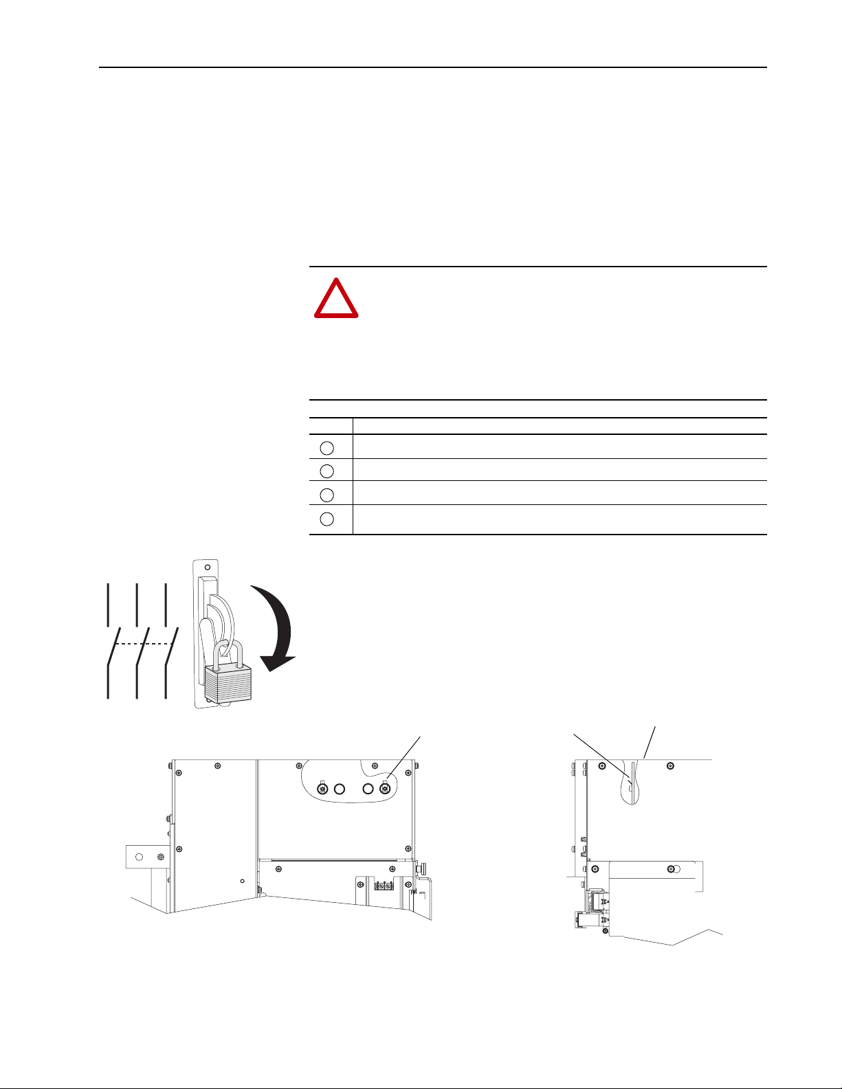
Step 1: Disconnect Power at the Branch Circuit
Step 2: Turn Off Drive Cabinet Circuit Breaker
Step 3: Verify that DC Bus Capacitors are Discharged
Disconnect input power upstream of the drive assembly cabinet. Follow
required safety procedures to lock out circuit during the repair.
Turn off the drive cabinet circuit breaker and open the drive cabinet doors.
ATTENTION: DC Bus capacitors retain hazardous voltages
after input power has been disconnected. After disconnecting
!
input power, wait five (5) minutes for the DC bus capacitors to
discharge and then check the voltage with a voltmeter to ensure
that the DC bus capacitors are discharged before touching any
internal components. Failure to observe this precaution could
result in severe bodily injury or loss of life.
Task Description
Turn off and lock out input power. Wait five minutes.
A
Verify that there is no voltage at the drive’s input power terminals.
B
Remove top cover.
C
Measure the DC bus potential with a voltmeter while standing on a non-conductive surface
D
and wearing insulated gloves (1000V).
L1 L2 L3
I
O
DC
Neg
(-)
DC Bus Measurement Points on
Laminated Bus Assembly
(0.25 x 0.32 in. male Faston).
Accessible by removal of top cover.
DC
Pos
(+)
Top Cover (Removed)
Front View of Inverter
Right Side View of Inverter
Loading...