


 Loading...
Rockwell Automation 1756-HYD02, 1756-M02AE, 1756-M02AS, 1756-M03SE, 1756- M08SE Configuration and Startup
...
SERCOS and Analog Motion
Configuration and Startup
1756-HYD02, 1756-M02AE, 1756-M02AS, 1756-M03SE, 1756M08SE, 1756-M16SE, 1768-M04SE, 2094-SE02F-M00-S0, 2094-SE02F-M00-S1
User Manual |
Original Instructions |
SERCOS and Analog Motion Configuration and Startup
Important User Information
Read this document and the documents listed in the additional resources section about installation, configuration, and operation of this equipment before you install, configure, operate, or maintain this product. Users are required to familiarize themselves with installation and wiring instructions in addition to requirements of all applicable codes, laws, and standards.
Activities including installation, adjustments, putting into service, use, assembly, disassembly, and maintenance are required to be carried out by suitably trained personnel in accordance with applicable code of practice.
If this equipment is used in a manner not specified by the manufacturer, the protection provided by the equipment may be impaired.
In no event will Rockwell Automation, Inc. be responsible or liable for indirect or consequential damages resulting from the use or application of this equipment.
The examples and diagrams in this manual are included solely for illustrative purposes. Because of the many variables and requirements associated with any particular installation, Rockwell Automation, Inc. cannot assume responsibility or liability for actual use based on the examples and diagrams.
No patent liability is assumed by Rockwell Automation, Inc. with respect to use of information, circuits, equipment, or software described in this manual.
Reproduction of the contents of this manual, in whole or in part, without written permission of Rockwell Automation, Inc., is prohibited.
Throughout this manual, when necessary, we use notes to make you aware of safety considerations.
WARNING: Identifies information about practices or circumstances that can cause an explosion in a hazardous environment, which may lead to personal injury or death, property damage, or economic loss.
ATTENTION: Identifies information about practices or circumstances that can lead to personal injury or death, property damage, or economic loss. Attentions help you identify a hazard, avoid a hazard, and recognize the consequence.
IMPORTANT Identifies information that is critical for successful application and understanding of the product.
Labels may also be on or inside the equipment to provide specific precautions.
SHOCK HAZARD: Labels may be on or inside the equipment, for example, a drive or motor, to alert people that dangerous voltage may be presen t.
BURN HAZARD: Labels may be on or inside the equipment, for example, a drive or motor, to alert people that surfaces may reach dangerous temperatures.
ARC FLASH HAZARD: Labels may be on or inside the equipment, for example, a motor control center, to alert people to potential Arc Flash. Arc Flash will cause severe injury or death. Wear proper Personal Protective Equipment (PPE). Follow ALL Regulatory requirements for sa fe work practices and for Personal Protective Equipment (PPE).
2 |
Rockwell Automation Publication MOTION-UM001I-EN-P - Septemberr 2020 |

Summary of changes
This manual includes new and updated information. Use these reference tables to locate changed information.
Grammatical and editorial style changes are not included in this summary.
Global changes
This table identifies changes that apply to all information about a subject in the manual and the reason for the change. For example, the addition of new supported hardware, a software design change, or additional reference material would result in changes to all of the topics that deal with that subject.
Change |
Topic |
|
|
Updated Legal notices. |
Legal notices on page 15 |
|
|
Updated branding. |
Throughout |
New or enhanced features
None in this version.
Rockwell Automation Publication MOTION-UM001I-EN-P - Septemberr 2020 |
3 |

Table of Contents
Summary of changes Preface
Configure analog motion
What you need ........................................................................................... |
11 |
Configuration and start-up scenarios...................................................... |
11 |
Description of the modules ................................................................. |
12 |
Help for selecting drives and motors........................................................ |
13 |
Additional resources .................................................................................. |
13 |
Legal notices ............................................................................................... |
15 |
Chapter 1 |
|
Introduction for Configure Analog Motion............................................. |
17 |
Create a controller project for Configure Analog Motion ...................... |
17 |
Set time synchronization for Configure Analog Motion ........................ |
19 |
Add an analog module .............................................................................. |
20 |
Modify properties for an analog module................................................. |
22 |
Add a hydraulic drive module................................................................... |
24 |
Modify properties for a hydraulic drive module............................... |
25 |
Configure the feedback type .............................................................. |
26 |
Add a motion group for Configure Analog Motion ................................ |
27 |
Set the Base Update Period ................................................................ |
28 |
Add an axis for Configure Analog Motion............................................... |
30 |
Configure an axis for Configure Analog Motion ..................................... |
31 |
Set the homing sequence for Configure Analog Motion .................. |
32 |
|
Chapter 2 |
|
Commission and tune |
Introduction for Commission and Tune ................................................. |
35 |
|
Download a program to the controller..................................................... |
35 |
|
Test axis wiring and direction................................................................... |
35 |
|
Tune a SERCOS axis................................................................................... |
36 |
|
Tune an analog axis.................................................................................... |
37 |
|
Troubleshoot faults ................................................................................... |
38 |
|
Manage motion faults ............................................................................... |
38 |
|
Configure the fault actions for an axis ..................................................... |
39 |
|
Set the fault action for an axis.................................................................. |
40 |
|
Inhibit an axis............................................................................................. |
41 |
|
Before you begin.................................................................................. |
42 |
|
Example: Inhibit an axis...................................................................... |
43 |
|
Example: Uninhibit an axis ................................................................. |
44 |
|
Test an axis with Motion Direct Commands ........................................... |
45 |
|
Access the Motion Direct Commands for a motion group .............. |
46 |
|
Access the Motion Direct Commands for an axis............................. |
46 |
|
Choose a command.............................................................................. |
47 |
|
Motion Direct Command dialog box................................................. |
50 |
|
Rockwell Automation Publication MOTION-UM001I-EN-P - Septemberr 2020 |
5 |

Table of Contents |
|
|
|
Motion Group Shutdown ................................................................... |
50 |
|
Motion Direct Command error process............................................. |
51 |
|
Motion Direct Command verification................................................ |
51 |
|
Motion Direct Command execution error ........................................ |
52 |
|
What if the software goes offline or the controller |
|
|
changes modes?................................................................................... |
52 |
|
Can two workstations give Motion Direct Commands? .................. |
52 |
|
Chapter 3 |
|
Program |
Introduction............................................................................................... |
53 |
|
Definition of Jerk ................................................................................. |
53 |
|
Choose a profile.................................................................................... |
53 |
|
Jerk Rate Calculation ........................................................................... |
54 |
|
Conversion from Engineering Units to % of Time...................... |
56 |
|
Use % of Time for the easiest programming of jerk.................... |
57 |
|
Velocity Profile Effects ................................................................. |
58 |
|
Jerk Programming in Units/Sec3................................................. |
58 |
|
Unique program considerations ................................................. |
58 |
|
Profile operand..................................................................................... |
59 |
|
Trapezoidal velocity profile........................................................... |
59 |
|
S-Curve velocity profile ................................................................ |
60 |
|
Backward compatibility ................................................................ |
61 |
|
Enter basic logic ........................................................................................ |
62 |
|
Example: Motion control program ..................................................... |
63 |
|
Download a program and run the logic ............................................ |
64 |
|
Choose a motion instruction.................................................................... |
64 |
|
Sample projects ......................................................................................... |
66 |
|
Troubleshoot axis motion.......................................................................... |
67 |
|
Why does my axis accelerate when I stop it? ..................................... |
67 |
|
Example .......................................................................................... |
67 |
|
Look For .......................................................................................... |
67 |
|
Cause............................................................................................... |
67 |
|
Corrective Action .......................................................................... |
69 |
|
Why does my axis overshoot its target speed?.................................. |
70 |
|
Example ......................................................................................... |
70 |
|
Look For ......................................................................................... |
70 |
|
Cause.............................................................................................. |
70 |
|
Corrective Action .......................................................................... |
72 |
|
Why is there a delay when I stop and then restart a jog? ................. |
72 |
|
Example ......................................................................................... |
72 |
|
Look For .......................................................................................... |
73 |
|
Cause............................................................................................... |
73 |
6 |
Rockwell Automation Publication MOTION-UM001I-EN-P - Septemberr 2020 |
|

Table of Contents
Home an axis
Axis properties
Corrective action............................................................................ |
74 |
Why does my axis overshoot its position and reverse direction?..... |
74 |
Example .......................................................................................... |
74 |
Look For .......................................................................................... |
74 |
Cause............................................................................................... |
75 |
Corrective action............................................................................ |
75 |
Chapter 4 |
|
Introduction for Home an Axis ................................................................ |
77 |
Guidelines for homing.............................................................................. |
78 |
Examples..................................................................................................... |
79 |
Active homing examples...................................................................... |
79 |
Passive homing examples................................................................... |
84 |
Homed Status...................................................................................... |
84 |
Feedback Integrity .............................................................................. |
84 |
Appendix A |
|
Introduction for Axis Properties ............................................................. |
85 |
General tab – AXIS_SERVO ..................................................................... |
85 |
General tab - AXIS_SERVO_DRIVE ........................................................ |
86 |
Node with a Kinetix 6000 drive ......................................................... |
87 |
General tab - AXIS_VIRTUAL................................................................... |
87 |
Motion Group ...................................................................................... |
87 |
MOTION_GROUP structure .............................................................. |
87 |
General tab – AXIS_GENERIC ................................................................. |
89 |
Motion Planner tab ................................................................................... |
89 |
Units tab...................................................................................................... |
91 |
Servo tab - AXIS_SERVO ........................................................................... |
91 |
Feedback tab – AXIS_SERVO ................................................................... |
92 |
Drive/Motor tab - AXIS_SERVO_DRIVE ................................................. |
95 |
Change Catalog Number ..................................................................... |
97 |
Calculate Position Parameters ............................................................ |
97 |
Motor Feedback tab - AXIS_SERVO_DRIVE .......................................... |
99 |
Aux Feedback tab - AXIS_SERVO_DRIVE .............................................. |
99 |
Conversion tab......................................................................................... |
100 |
Homing tab - AXIS_SERVO..................................................................... |
101 |
Homing tab - AXIS_SERVO_DRIVE....................................................... |
103 |
Homing tab - AXIS_VIRTUAL................................................................. |
105 |
Hookup tab - AXIS_SERVO ..................................................................... |
106 |
Hookup tab - AXIS_SERVO_DRIVE ....................................................... |
107 |
Tune tab - AXIS_SERVO, AXIS_SERVO_DRIVE................................... |
108 |
Start Tuning ....................................................................................... |
110 |
Rockwell Automation Publication MOTION-UM001I-EN-P - Septemberr 2020 |
7 |

Table of Contents
Motion axis attributes
Wiring diagrams
8
Dynamics tab - AXIS_SERVO, AXIS_SERVO _DRIVE, |
|
AXIS_VIRTUAL.......................................................................................... |
111 |
Calculate .............................................................................................. |
113 |
Manual Adjust for Dynamics tab ....................................................... |
113 |
Gains tab - AXIS_SERVO......................................................................... |
114 |
Manual Adjust for Gains tab............................................................... |
117 |
Gains Tab - AXIS_SERVO_DRIVE ........................................................... |
117 |
Manual Adjust for Gains tab.............................................................. |
121 |
Set custom gains ................................................................................ |
121 |
Output tab - AXIS_SERVO ...................................................................... |
121 |
Manual Adjust for Output tab ........................................................... |
124 |
Output tab - AXIS_SERVO_DRIVE......................................................... |
124 |
Manual Adjust for Output tab ........................................................... |
125 |
Limits tab - AXIS_SERVO........................................................................ |
126 |
Manual Adjust for Limits tab ............................................................ |
127 |
Limits tab - AXIS_SERVO_DRIVE .......................................................... |
127 |
Manual Adjust for Limits tab ............................................................ |
129 |
Set custom limits................................................................................ |
130 |
Offset tab - AXIS_SERVO ........................................................................ |
132 |
Manual Adjust for Offset tab............................................................. |
134 |
Offset tab - AXIS_SERVO_DRIVE .......................................................... |
134 |
Manual adjust for Offset tab ............................................................. |
136 |
Fault Actions tab - AXIS_SERVO ............................................................ |
136 |
Fault Actions tab - AXIS_SERVO_DRIVE............................................... |
138 |
Set custom stop action....................................................................... |
140 |
Tag tab....................................................................................................... |
142 |
Monitoring axis tags ................................................................................ |
142 |
Create reports ........................................................................................... |
143 |
Appendix B |
|
Introduction for Motion Axis Attributes ............................................... |
147 |
Accessing an MSG instruction .......................................................... |
147 |
Interpreting the Attribute Tables...................................................... |
147 |
Replicated Attributes ......................................................................... |
148 |
Axis attributes........................................................................................... |
148 |
Additional error code information ......................................................... |
234 |
Appendix C |
|
Introduction for Wiring Diagrams ........................................................ |
235 |
1756-M02AE module ................................................................................ |
235 |
Ultra 100 Series Drive............................................................................... |
235 |
Ultra 200 Series Drive .............................................................................. |
236 |
Rockwell Automation Publication MOTION-UM001I-EN-P - Septemberr 2020 |
|

Table of Contents
Servo loop block diagrams
Index
1398-CFLAExx cable............................................................................ |
237 |
Pinouts for 1398-CFLAExx cable....................................................... |
238 |
Ultra3000 Drive ........................................................................................ |
239 |
Ultra3000 to 1756-M02AE interconnect diagram ............................ |
239 |
2090-U3AE-D44xx cable.................................................................... |
240 |
1756-M02AS module ................................................................................ |
240 |
Wiring from AB 842A encoder without reset to 1756-M02AS RTB.241 |
|
Wiring for AB 842A encoder with remote reset |
|
to 1756-M02AS RTB ........................................................................... |
242 |
1756-HYD02 application example............................................................ |
243 |
1756-HYD02 module ................................................................................. |
243 |
LDTs........................................................................................................... |
244 |
Temposonic GH feedback device ............................................................ |
245 |
24V registration sensor ............................................................................ |
245 |
5V registration sensor ............................................................................. |
246 |
Home limit switch input......................................................................... |
246 |
OK contacts.............................................................................................. |
246 |
Appendix D |
|
Introduction for Servo Loop Block Diagrams ...................................... |
249 |
Interpreting the diagrams ..................................................................... |
249 |
AXIS_SERVO ........................................................................................... |
250 |
Position servo with torque servo drive ............................................ |
250 |
Position servo with velocity servo drive ........................................... |
251 |
AXIS_SERVO_DRIVE ............................................................................. |
252 |
Motor Position Servo ........................................................................ |
252 |
Auxiliary Position Servo .................................................................... |
253 |
Dual Position Servo............................................................................ |
254 |
Motor Dual Command Servo ............................................................ |
255 |
Auxiliary Dual Command Servo ....................................................... |
256 |
Dual Command Feedback Servo....................................................... |
256 |
Velocity Servo ..................................................................................... |
257 |
Torque Servo....................................................................................... |
257 |
Drive Gains ......................................................................................... |
257 |
Rockwell Automation Publication MOTION-UM001I-EN-P - Septemberr 2020 |
9 |
Preface
What you need
Configuration and start-up scenarios
This manual is a redesigned manual from publication LOGIX-UM002. A companion manual is available, which is Coordinate System User Manual, publication MOTION -UM002.
This manual is designed to give you the quickest and easiest approach to a SERCOS or Analog control solution. If you have any comments or suggestions, please see Documentation Feedback on the back cover of this manual.
To configure a SERCOS or Analog motion system requires:
SERCOS
•Logix L6x, Logix L7x, or Logix L8x controller
•SERCOS interface drive (6000, 6200, 2000, Ultra3000)
•SERCOS interface module
•Kinetix 6000 drive/actuators pair
•Logix Designer application
Analog
•Logix L6x controller
•Analog interface module
•Analog interface drive, Ultra3000
•Kinetix 6000 drive/actuators pair
•Logix Designer application
These three example scenarios describe how to get a motion solution up and running.
Tip: Programming Virtual first is the safest method to begin with because it separates the motion programming from the hardware.
Rockwell Automation Publication MOTION-UM001I-EN-P - Septemberr 2020 |
11 |

Preface
Description of the modules |
This table describes the Logix 5000 motion modules. |
|
|
Motion Module |
Description |
|
|
|
|
1756-M03SE |
Use a SERCOS interface module to connect the |
|
1756-M08SE |
controller to SERCOS interface drives. |
|
1756-M16SE |
• The SERCOS interface module uses high-speed, real |
|
1768-M04SE |
time, serial communication to control digital drives. |
|
|
• SERCOS is the IEC 61491 Serial Real-time |
|
|
Communication System protocol over a fiber optic |
|
|
network. |
|
|
• The module uses a fiber optic network for all the |
|
|
wiring between the drives and the module. |
|
2094-SE02F-M00-S0, 2094- |
Kinetix 6200 control modules use SERCOS interface to |
|
SE02F-M00-S1 |
communicate with the Logix controller and |
|
|
EtherNet/IP to access the safety configuration tool. |
|
1756-M02AE |
The 1756-M02AE module is a two-axis servo module for |
|
|
drives/actuators that need a ±10V velocity or torque |
|
|
reference. Use the 1756-M02AE module when the |
|
|
equipment has quadrature encoder feedback. |
|
|
The module also has: |
|
|
• Home limit switch inputs |
|
|
• Drive fault inputs |
|
|
• Drive enable outputs |
|
|
• 5V or 24V position registration inputs |
|
|
• 250 µs position and velocity loop updates |
|
|
|
|
1756-HYD02 |
The 1756-HYD02 module is a two-axis servo module for |
|
|
hydraulic actuators that need a ±10V velocity |
|
|
reference. Use the 1756-HYD02 module when the |
|
|
equipment has magnostrictive linear transducer (LDT) |
|
|
feedback. |
|
|
The module is similar to the 1756-M02AE module with |
|
|
these exceptions. |
|
|
• Feed Forward adjust and single-step Auto Tune. |
|
|
• Gain ratio between extend direction and retract |
|
|
direction to accommodate hydraulic cylinder |
|
|
dynamics. |
|
|
• Intelligent transducer noise detection filtering in |
|
|
hardware and firmware replaces programmable IIR |
|
|
filtering. |
12 |
Rockwell Automation Publication MOTION-UM001I-EN-P - Septemberr 2020 |

Preface
Motion Module |
Description |
|
|
1756-M02AS |
The 1756-M02AS module is a two-axis servo module for |
|
drives/actuators that need a ±10V velocity or torque |
|
reference input. Use the 1756-M02AS module when the |
|
equipment has Serial Synchronous Input (SSI) position |
|
feedback. |
|
The module is similar to the 1756-M02AE module with |
|
these exceptions: |
|
• Gain ratio between extend direction and retract |
|
direction to accommodate hydraulic cylinder |
|
dynamics. |
|
• Intelligent transducer noise detection filtering in |
|
hardware and firmware replaces programmable IIR |
|
filtering. |
|
• SSI interface consisting of Differential Clock output |
|
and Data return signals replaces the differential |
|
encoder interface. |
Help for selecting drives and motors
Additional resources
Use the Motion Analyzer utility to select the Rockwell Automation drives and motors based upon the load characteristics and typical motion application cycles.
Access and download the program at the Motion Analyzer Software web page.
The Motion Analyzer offers wizard-like screens to collect information about the application. After entering the information, for example, the load inertia, gear box ratio, feedback device, and brake requirements, the Motion Analyzer generates an easy-to-read list of recommended motors, drives, and other support equipment.
These documents contain additional information concerning related Rockwell Automation products. View or download publications at the Literature Library. To order paper copies of technical documentation, contact your local Rockwell Automation distributor or sales representative.
Resource |
Description |
|
|
Motion Coordinate System User |
Provides details on how to create and |
Manual, publication MOTION-UM002. |
configure a coordinated motion system. |
|
|
Logix 5000 Controller Motion |
Provides a programmer with details about |
Instructions Reference Manual, |
motion instructions for a Logix-based |
publication MOTION-RM002. |
controller. |
Logix 5000 Controllers Quick Start, |
Describes how to get started |
publication 1756-QS001. |
programming and maintaining Logix 5000 |
|
controllers. |
Logix 5000 Controllers Common |
Provides detailed and comprehensive |
Procedures, publication 1756-PM001. |
information about how to program a |
|
Logix 5000 controller. |
Logix 5000 Controllers General |
Provides a programmer with details about |
Instructions Reference Manual, |
general instructions for a Logix-based |
publication 1756-RM003. |
controller. |
Rockwell Automation Publication MOTION-UM001I-EN-P - Septemberr 2020 |
13 |

Preface
Resource |
Description |
|
|
Logix 5000 Controllers Advanced |
Provides a programmer with details about |
Process Control and Drives |
process and drives instructions for a |
Instructions Reference Manual, |
Logix-based controller. |
publication 1756-RM006. |
|
PhaseManager User Manual, |
Describes how to configure and program |
publication LOGIX-UM001. |
a Logix 5000 controller to use equipment |
|
phases. |
ControlLogix System User Manual, |
Describes the necessary tasks to install, |
publication 1756-UM001. |
configure, program, and operate a |
|
ControlLogix system. |
CompactLogix Controllers User Manual, |
Describes the necessary tasks to install, |
publication 1768-UM001. |
configure, program, and operate a |
|
CompactLogix system. |
Analog Encoder (AE) Servo Module |
Provides installation instructions for the |
Installation Instructions, publication |
Analog Encoder (AE) Servo Module, catalog |
1756-IN047. |
number 1756-M02AE. |
|
|
ControlLogix SERCOS interface Module |
Provides installation instructions for the |
Installation Instructions, publication |
ControlLogix SERCOS interface modules, |
1756-IN572. |
catalog number 1756-M03SE, 1756-M08SE, |
|
1756-M16SE, 1756-M08SEG. |
CompactLogix SERCOS interface |
Provides installation instructions for the |
Module Installation Instructions, |
CompactLogix SERCOS interface Module, |
publication 1768-IN005. |
catalog number 1768-M04SE. |
|
|
Ultra3000 Digital Servo Drives |
Provides the mounting, wiring, and |
Installation Manual, publication 2098- |
connecting procedures for the Ultra3000 |
IN003. |
drives and standard Rockwell |
|
Automation/Allen-Bradley motors |
|
recommended for use with the Ultra3000 |
|
drives. |
Ultra3000 Digital Servo Drives |
Provides powerup procedures, system |
Integration Manual, publication 2098- |
integration, and troubleshooting tables |
IN005. |
for the Ultra3000 digital servo drives. |
|
|
Kinetix 7000 High Power Servo Drive |
Provides details on how to plan for, |
User Manual, publication 2099-UM001. |
mount, install, configure, and |
|
troubleshoot the Kinetix 7000 High Power |
|
Servo drive. |
Kinetix 6000 Multi-axis Servo Drives |
Provides detailed installation instructions |
User Manual, publication 2094-UM001. |
for mounting, wiring, and troubleshooting |
|
the Kinetix 6000 drive, and system |
|
integration for the drive/motor |
|
combination with a Logix controller. |
Kinteix 6200 and Kinetix 6500 Safe |
Provides information on wiring, |
Speed Monitoring Multi-axis Servo |
configuring, and troubleshooting the |
Drives Safety Reference Manual, |
safety functions of the Kinetix 6200 and |
publication 2094-RM001. |
Kinetix 6500 drives. |
Kinetix 6200 and Kinetix 6500 Safe |
|
Torque-off Multi-axis Servo Drives |
|
Safety Reference Manual, publication |
|
2094-RM002. |
|
14 |
Rockwell Automation Publication MOTION-UM001I-EN-P - Septemberr 2020 |

Preface
Resource |
Description |
|
|
8720MC High Performance Drives |
Provides the mounting, wiring, and |
Installation manual, publication |
connecting procedures for the 8720MC |
8720MC-IN001. |
and standard Rockwell Automation/Allen- |
|
Bradley motors recommended for use |
|
with the 8720MC drive. |
8720MC High Performance Drives |
Provides the startup, configuration, and |
Integration manual, publication |
troubleshooting procedures for the |
8720MC-IN002. |
8720MC drive. |
|
|
Industrial Automation Wiring and |
Provides general guidelines for installing |
Grounding Guidelines, publication 1770- |
a Rockwell Automation industrial system. |
4.1. |
|
Product Certifications site. |
Provides declarations of conformity, |
|
certificates, and other certification |
|
details. |
Legal notices
Rockwell Automation publishes legal notices, such as privacy policies, license agreements, trademark disclosures, and other terms and conditions on the Legal Notices page of the Rockwell Automation website.
End User License Agreement (EULA)
You can view the Rockwell Automation End User License Agreement (EULA) by opening the license.rtf file located in your product's install folder on your hard drive.
The default location of this file is:
C:\Program Files (x86)\Common Files\Rockwell\license.rtf.
Open Source Software Licenses
The software included in this product contains copyrighted software that is licensed under one or more open source licenses.
You can view a full list of all open source software used in this product and their corresponding licenses by opening the oss_license.txt file located your product's OPENSOURCE folder on your hard drive. This file is divided into these sections:
•Components
Includes the name of the open source component, its version number, and the type of license.
•Copyright Text
Includes the name of the open source component, its version number, and the copyright declaration.
Rockwell Automation Publication MOTION-UM001I-EN-P - Septemberr 2020 |
15 |

Preface
•Licenses
Includes the name of the license, the list of open source components citing the license, and the terms of the license.
The default location of this file is:
C:\Program Files (x86)\Common Files\Rockwell\Help\<product name>\Release Notes\OPENSOURCE\oss_licenses.txt.
You may obtain Corresponding Source code for open source packages included in this product from their respective project web site(s). Alternatively, you may obtain complete Corresponding Source code by contacting Rockwell Automation via the Contact form on the Rockwell Automation website: http://www.rockwellautomation.com/global/aboutus/contact/contact.page. Please include "Open Source" as part of the request text.
16 |
Rockwell Automation Publication MOTION-UM001I-EN-P - Septemberr 2020 |

Chapter 1
Configure analog motion
Introduction for Configure
Analog Motion
Create a controller project for Configure Analog Motion
Use this chapter for step-by-step procedures on how to configure analog motion control.
Use these instructions to create a controller project.
To create a controller project for Configure SERCOS Motion:
1. Open the Studio 5000 software.
2.In the Studio 5000 launcher, under Create, select New Project.
3.On the New Project dialog box, choose a controller.
Rockwell Automation Publication MOTION-UM001I-EN-P - Septemberr 2020 |
17 |

Chapter 1 Configure analog motion
4.In the Name box, type a name for the controller project, and select
Next.
5.In the Revision list, select the revision number for the controller.
6.In the Chassis list, select the type of chassis that holds the controller.
7.In the Slot list, select the physical slot where the controller is located.
8.In the Security Authority list, select a security option:
•No Protection - All users can view and edit the project.
•FactoryTalk Security - Only users authenticated through FactoryTalk Security can view and edit the project
9.(optional) Select Use only the selected Security Authority for authentication and authorization to associate this project with a specific Security Authority. When this check box is selected, users interacting with this project must be authenticated and authorized by the same Security Authority that was used to secure the project. Otherwise, unauthenticated users must rely on Guest User
permissions.
Tip: Guest User permissions are cached within the project. The Logix Designer application uses Guest User permissions when the project is opened but not connected to the FactoryTalk Security Authority that secures the project. By default, all Guest User permissions are denied. Guest User permissions are configured in the FactoryTalk Administration Console.
10.Select Logical Name <Controller Name> or Permission Set to apply specific permissions to the controller.
Select Logical Name <Controller Name> to apply a Logical Name in FactoryTalk Services Platform that has the same name as the controller. If there is no existing Logical Name that matches the controller name, a new Logical Name is created with the controller's name. The new Logical Name inherits permissions from its parent
18 |
Rockwell Automation Publication MOTION-UM001I-EN-P - Septemberr 2020 |

Chapter 1 Configure analog motion
resource. See FactoryTalk Help for more information on how networks and devices inherit security permissions.
Select Permission Set to apply a specific set of permissions to the controller. The permission sets in the list are maintained in FactoryTalk Services Platform and identify a set of actions that are allowed or denied for a particular user and computer combination.
11. (optional) In the Description box, type a description for the controller.
Tip: The description is limited to 128 bytes. Standard ASCII characters consume 1 byte per character, allowing for 128 characters. Characters in some languages require up to three bytes per character, resulting in less than 128 characters.
12.(optional) Select Enable redundancy if this project supports an automatic transfer of project control to a redundant controller in case of primary controller failure.
13.Select Finish.
Set time synchronization for Configure Analog Motion
See also
Add a SERCOS motion module
Add a SERCOS interface drive module
Add a motion group for Configure SERCOS motion
1. Add an axis
Time Synchronization in ControlLogix is called CIP Sync. CIP Sync is a layer of functionality that Rockwell Automation has developed on top of the IEEE 1588 PTP protocol. CIP Sync maintains accurate time synchronization of automation solutions.
This setting establishes the module to participate in time synchronization. In systems with multiple processors, all controllers must have time synchronization enabled if they use CSmainT/PTP time. The 1756-ENxT communication modules win the arbitration over any processor.
To set time synchronization for Configure SERCOS Motion:
1. In the Controller Organizer, double-click the controller.
Rockwell Automation Publication MOTION-UM001I-EN-P - Septemberr 2020 |
19 |
Chapter 1 Configure analog motion
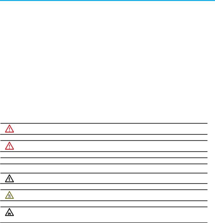
2. On the Controller Properties dialog box, select the Date/Time tab.
3.Select Enable Time Synchronization.
4.Select OK.
Without intervention, the Grandmaster is PTP and CST master. Use the settings on the Advanced dialog box to let this module win the arbitration over other processors and communication modules in the chassis.
See also
Add an analog module
Integrated Architecture and CIP Sync Configuration Application Technique, publication IA-AT003
Use these instructions to add an analog module to the system.
IMPORTANT For all modules, use the firmware revision that goes with the firmware revision of the controller. See the release notes for the controller’s firmware.
To add an analog module:
1.In the Controller Organizer, right-click the backplane and select New Module.
20 |
Rockwell Automation Publication MOTION-UM001I-EN-P - Septemberr 2020 |
Chapter 1 Configure analog motion
2.On the Select Module Type dialog box, choose the module to add to the project.
3.Select Close on Create, and select Create.
4.On the New Module dialog box, in Name, type a name for the module.
5.In Slot, choose the number that corresponds to the physical slot that contains the module.
6.(optional) In Description, type a description.
7.In Electronic Keying, choose a keying option of either Compatible Keying or Exact Match.
WARNING: Disable Keying should never be used with motion modules.
8.Select Open Module Properties, and select OK. Continue with the procedure to modify the properties for the module.
See also
Electronic Keying
Rockwell Automation Publication MOTION-UM001I-EN-P - Septemberr 2020 |
21 |
Chapter 1 Configure analog motion
Modify properties for an analog module
22
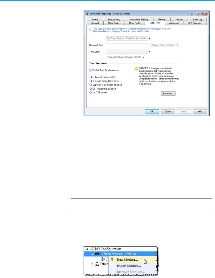
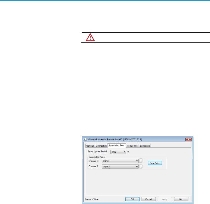
Use the Module Properties dialog box to modify properties and associate axes with the module.
To modify the properties for an analog module:
1.In the Controller Organizer, double-click the module.
2.On the Module Properties Report dialog box, select the Associated Axes tab.
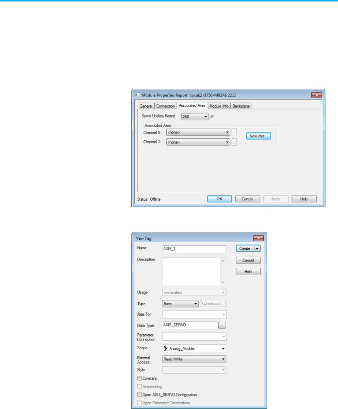
3.Select New Axis to create an axis to associate with this module.
4.On the New Tag dialog box, type a name for the Axis and select Create.
5.On the Module Properties Report dialog box, in Channel 0, choose the new axis to assign it to the module.
6.Select Browse to open the Axis Properties dialog box for the associated axis.
Rockwell Automation Publication MOTION-UM001I-EN-P - Septemberr 2020
Chapter 1 Configure analog motion
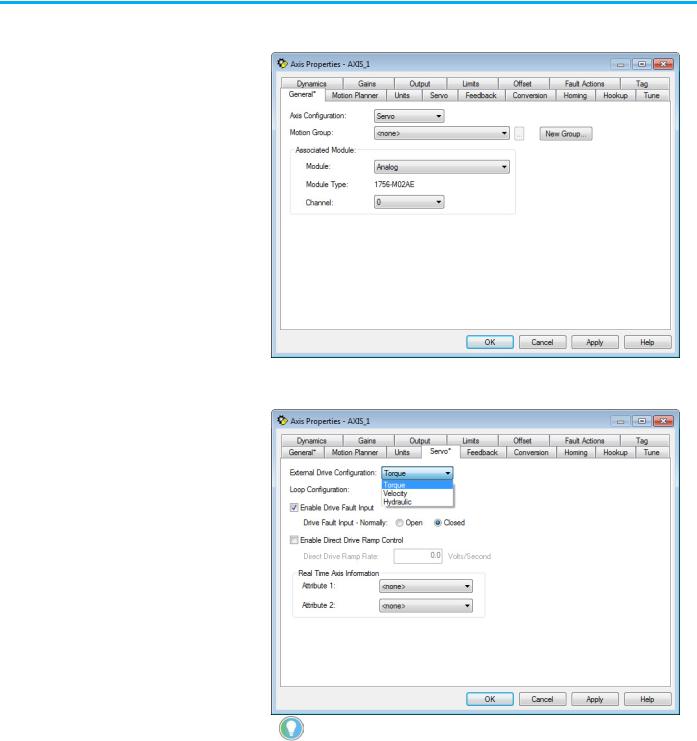
7.On the Axis Properties dialog box, in Module on the General tab, choose the module to associate with the axis.
8.Select the Servo tab.
9.In External Drive Configuration, choose the drive configuration.
Tip: If configuring a torque drive, the drive must be able to be configured for torque. Hydraulic can only be selected for a hydraulic module.
10. Select OK.
See also
Add a motion group for Configure Analog Module on page 27
Add an axis for Configure Analog Module on page 30
Rockwell Automation Publication MOTION-UM001I-EN-P - Septemberr 2020 |
23 |

Chapter 1 Configure analog motion
Add a hydraulic drive module
24
Use these instructions to add a hydraulic drive module if included in the configuration.
To add a hydraulic drive module:
IMPORTANT For all modules, use the firmware revision that goes with the firmware revision of the controller. See the release notes for the controller’s firmware.
1.In the Controller Organizer, right-click the backplane and select New Module.
2.On the Select Module Type dialog box, choose the hydraulic drive module to add to the project.
3.Select Close on Create, and select Create.
4.On the New Module dialog box, in Name, type a name for the module.
Rockwell Automation Publication MOTION-UM001I-EN-P - Septemberr 2020
Chapter 1 Configure analog motion
5.In Slot, choose the number that corresponds to the physical slot that contains the module.
6.(optional) In Description, type a description.
7.In Electronic Keying, choose either Compatible Keying or Exact Match.
WARNING: WARNING: Never select Disable Keying with motion modules
8.Select Open Module Properties.
9.Select OK. Continue with the instructions to modify the properties for the hydraulic drive module.
Modify properties for a hydraulic drive module
Configure the feedback type for a hydraulic drive. Based on the length of the feedback, the Servo Update Period must be configured. This setting is unique for the 1756-HYD02 module. If the Servo Update Period is not configured correctly, the axis does not work.
To modify the properties for a hydraulic drive module:
1.If the Module Properties Report dialog box is not already open, in the Controller Organizer, double-click the hydraulic drive module.
2.On the Module Properties Report dialog box, select the Associated Axes tab.
3.Select New Axis to create an AXIS_SERVO tag to associate to one of the channels.
Rockwell Automation Publication MOTION-UM001I-EN-P - Septemberr 2020 |
25 |

Chapter 1 Configure analog motion
4. On the New Tag dialog box, in Name, type a name for the axis tag.
5.Select Create.
6.(optional) Repeat steps 3 through 5 if an additional axis is required.
7.On the Module Properties Report dialog box, in Channel 0, choose an axis.
8.(optional) In Channel 1, choose an axis.
9.In Servo Update Period, choose the periodic rate at which the module closes the servo loop for an axis.
10.Select OK.
See also
Configure the feedback type
Configure the feedback type on page 26
Use these instructions to configure the feedback type for the axis.
1. In the Controller Organizer, double-click the axis.
26 |
Rockwell Automation Publication MOTION-UM001I-EN-P - Septemberr 2020 |

Chapter 1 Configure analog motion
Add a motion group for Configure Analog Motion
2. On the Axis Properties dialog box, select the Feedback tab.
3.In Feedback Type, choose the feedback type.
4.In Calibration Constant, choose the value and select Calculate. The minimum servo update period for the configured feedback appears.
5.If necessary, return to the Module Properties dialog box, and modify the settings on the Associated Axis tab.
See also
Feedback tab - AXIS_SERVO on page 92
Use these instructions to add a motion group.
IMPORTANT Only one motion group can be created for each project.
Rockwell Automation Publication MOTION-UM001I-EN-P - Septemberr 2020 |
27 |
Chapter 1 Configure analog motion
To add a motion group for Configure Analog Motion:
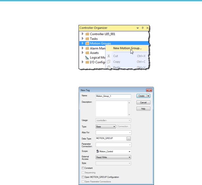
1.In the Controller Organizer, right-click Motion Groups and select New Motion Group.
2.On the New Tag dialog box, in Name, type a name for the motion group.
|
3. (optional) In Description, type a description. |
|
4. Select Create. |
|
See also |
|
Add an axis for Configure Analog Motion on page 30 |
Set the Base Update Period |
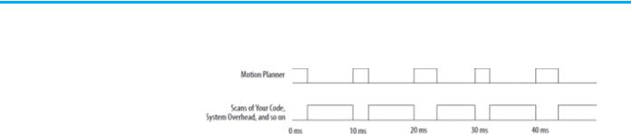
The Base Update Period (also known as the Coarse Update Period) is how |
|
often the motion planner runs. The motion planner is the part of the |
|
controller that handles position and velocity information for the axes. When |
|
the motion planner runs, it interrupts most other tasks regardless of their |
|
priority. |
28 |
Rockwell Automation Publication MOTION-UM001I-EN-P - Septemberr 2020 |
Chapter 1 Configure analog motion
Example: If the Base Update Period is set to 10 ms, then every 10 ms the controller stops scanning the code and performing other system overhead tasks, and runs the motion planner.
Use these guidelines to set the Base Update Period.
Guideline |
Description |
|
|
Number of Axes |
1756-L6x controller 4 axes/ms |
|
1756-L7x controller8 axes/ms |
|
|
Save Controller’s Time |
Leave at least half the controller’s time for the scan |
|
of all the code. |
|
|
Base Update Period and |
For SERCOS interface motion modules, set the Base |
SERCOS modules |
Update Period to a multiple of the cycle time of the |
|
motion module. |
|
Example: If the cycle time is 2 ms, set the Base |
|
Update Period to 8 ms, 10 ms, 12ms, and so on. |
|
|
Base Update Period and |
For analog motion modules, set the Base Update |
Analog modules |
Period to: |
|
• At least 3 times the servo update period of the |
|
motion module. |
|
• A multiple of the servo update period of the |
|
motion module. |
To set the Base Update Period:
1. In the Controller Organizer, double-click the motion group.
Rockwell Automation Publication MOTION-UM001I-EN-P - Septemberr 2020 |
29 |
Chapter 1 Configure analog motion
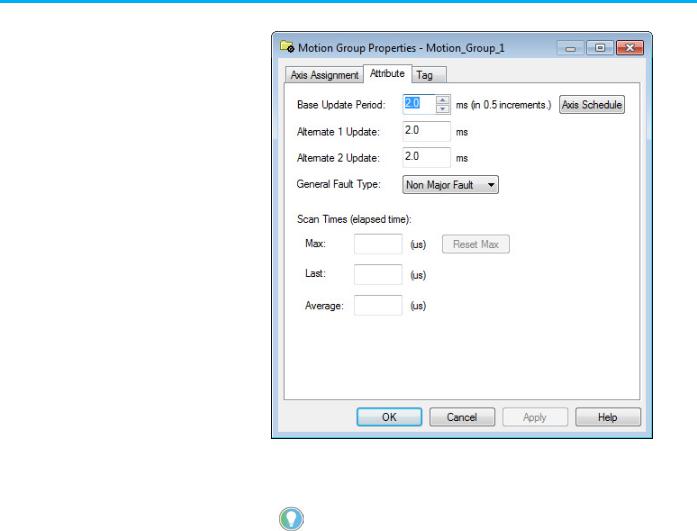
2. Select the Attribute tab.
Add an axis for Configure Analog Motion
3.In Base Update Period, choose the update period using the guidelines mentioned earlier. The valid values range from 0.5 to 32, in 0.5
increments.
Tip: The Axis Schedule button opens the Axis Schedule dialog box to schedule the base and alternate update periods and assign axes to them. Since axes used in coordinate system objects cannot be multiplexed, only the Base Update Period is used. Therefore, there is no need to open the Axis Schedule dialog box.
4.In General Fault Type, choose Non Major Fault.
5.Select OK.
See also
1. Manage motion faults on page 38
Use these instructions to add an axis for each of the drives.
30 |
Rockwell Automation Publication MOTION-UM001I-EN-P - Septemberr 2020 |
Loading...