


 Loading...
User's Manual
ATS Software
PWM 20 (IK 215)
Software 539862-23 Version 3.0.xx
11/2014

1 General information .............................................................................................................. |
5 |
|
1.1 |
How to Use this Manual.................................................................................................. |
5 |
1.2 |
Safety precautions......................................................................................................... |
.. 6 |
1.3 |
Information on the IK 215 adjusting and testing package ............................................... |
7 |
1.4 |
IK 215 adjusting and testing package (ID 547858-xx); items supplied ............................ |
8 |
1.5 |
Information on the PWM 20 encoder diagnostic kit, ID 759251-xx................................. |
9 |
1.6 |
PWM 20 basic kit, ID 731626-51; items supplied ........................................................... |
9 |
1.7 |
PWM 20 encoder diagnostic kit, ID 759251-01; items supplied ................................... |
10 |
2 Optional cables and pin layouts ........................................................................................ |
11 |
|
2.1 |
Optional cables and adapters ....................................................................................... |
11 |
2.2 |
Scope of functions of the ATS software 3.0 ................................................................. |
12 |
3 Commissioning .................................................................................................................... |
13 |
|
3.1 |
System requirements .................................................................................................... |
13 |
3.2 |
Description of the hardware .......................................................................................... |
13 |
3.3 |
Installing the ATS Software ........................................................................................... |
14 |
3.4 |
Uninstalling the ATS software ....................................................................................... |
14 |
3.5 |
Calibration...................................................................................................................... |
15 |
3.6 |
Configuration ................................................................................................................. |
16 |
|
3.6.1 Configure hardware ............................................................................................. |
17 |
|
3.6.2 Language selection .............................................................................................. |
18 |
|
3.6.3 Manage product keys .......................................................................................... |
19 |
|
3.6.4 Display of software and database versions ......................................................... |
22 |
|
3.6.5 Finding documentation (Help files) of the ATS software ..................................... |
22 |
|
3.6.6 Updates of the ATS help files (PDF file) .............................................................. |
23 |
4 Identifying encoder output signals (encoder interfaces) ................................................. |
25 |
|
4.1 |
Incremental interfaces................................................................................................... |
25 |
4.2 |
Absolute interfaces........................................................................................................ |
26 |
5 Software description ........................................................................................................... |
27 |
|
5.1 |
Operational design......................................................................................................... |
27 |
5.2 |
Setting up a connection to the encoder ........................................................................ |
28 |
|
5.2.1 Feed-through mode ............................................................................................. |
30 |
|
5.2.2 Automatic encoder identification by entering the ID ........................................... |
34 |
|
5.2.3 Manual encoder selection .................................................................................... |
38 |
5.3 |
Basic functions .............................................................................................................. |
45 |
|
5.3.1 Position display .................................................................................................... |
46 |
|
5.3.2 Incremental signal display .................................................................................... |
70 |
|
5.3.3 Display encoder memory ..................................................................................... |
78 |
|
5.3.4 Comparing contents of encoder memories ......................................................... |
88 |
|
5.3.5 Voltage display ..................................................................................................... |
91 |
5.4 |
Add-on info (EnDat 2.2): Temperature display............................................................... |
93 |
5.5 |
Diagnostics .................................................................................................................... |
95 |
|
5.5.1 Absolute/incremental deviation ........................................................................... |
95 |
|
5.5.2 Online diagnostics ............................................................................................... |
99 |
5.6 |
Testing Functional Safety ............................................................................................ |
109 |
|
5.6.1 Test of forced dynamic sampling ....................................................................... |
112 |
|
5.6.2 Test for consistency .......................................................................................... |
114 |
|
5.6.3 Test by comparison of position values 1 and 2 .................................................. |
117 |
5.7 |
Supported interfaces ................................................................................................... |
122 |
|
5.7.1 SSI, SSI programmable ...................................................................................... |
122 |
|
5.7.2 Fanuc ................................................................................................................. |
124 |
|
5.7.3 Mitsubishi .......................................................................................................... |
126 |

5.7.4 Indramat (I2C) .................................................................................................... |
127 |
5.7.5 DRIVE-CLiQ ....................................................................................................... |
130 |
5.7.6 Yaskawa serial interface .................................................................................... |
144 |
5.7.7 Panasonic serial interface .................................................................................. |
145 |
6 Checking incremental encoders ....................................................................................... |
147 |
6.1 General information..................................................................................................... |
147 |
6.2 Analog output signals .................................................................................................. |
147 |
6.2.1 Connecting the encoder .................................................................................... |
147 |
6.2.2 Checking incremental signals ............................................................................ |
148 |
6.2.3 Description of the incremental signal display .................................................... |
151 |
6.2.4 Checking the reference signal (1 Vpp / 11 µApp) .............................................. |
162 |
6.2.5 Zoom function for oscilloscope ......................................................................... |
166 |
6.2.6 Recording function ............................................................................................ |
167 |
6.2.7 Counter function ................................................................................................ |
174 |
6.2.8 PWT test function .............................................................................................. |
181 |
6.2.9 Checking a commutation encoder with Zn and Z1 track (e.g. ERN 1387) ......... |
185 |
6.2.10 Checking homing/limit signals ......................................................................... |
191 |
6.3 Digital TTL/HTL square-wave output signals .............................................................. |
195 |
6.3.1 General information ........................................................................................... |
195 |
6.3.2 Explanation of the display .................................................................................. |
197 |
6.3.3 Level function Bar of oscilloscope settings, TTL ............................................ |
198 |
6.3.4 Level function Oscilloscope display, TTL ........................................................ |
199 |
6.3.5 Level function Bar graph display, TTL level .................................................... |
201 |
6.3.6 Logic function, TTL ............................................................................................ |
202 |
6.3.7 Logic function, bar graphs ................................................................................. |
204 |
6.3.8 Counter function ................................................................................................ |
206 |
6.4 Mounting wizards........................................................................................................ |
208 |
6.4.1 General information ........................................................................................... |
208 |
7 Interface description.......................................................................................................... |
209 |
7.1 General information..................................................................................................... |
209 |
7.2 Analog interfaces ........................................................................................................ |
209 |
7.2.1 Incremental signals11 µApp .............................................................................. |
209 |
7.2.2 Incremental signals 1 Vpp ................................................................................. |
212 |
7.2.3 Incremental signals1Vpp with commutating signals ......................................... |
215 |
7.3 Square-wave interfaces............................................................................................... |
216 |
7.3.1 Incremental signals TTL square-wave interface ............................................... |
216 |
7.3.2 Incremental signals HTL (HTLs) square-wave interface .................................... |
219 |
7.4 Absolute interface ....................................................................................................... |
222 |
7.4.1 EnDat ................................................................................................................. |
222 |
7.4.2 Synchronous serial interface; programming via connector ................................ |
235 |
7.4.3 SSI synchronous serial interface with programming interface |
|
(older rotary encoders) ...................................................................................... |
238 |
7.4.4 Company-specific interfaces ............................................................................. |
242 |
8 Contacts.............................................................................................................................. |
243 |
8 Your HEIDENHAIN helpline............................................................................................ |
243 |
8 The HEIDENHAIN technical helpline .............................................................................. |
243 |
8 HEIDENHAIN Helpline for |
|
repairs, spare parts, exchange units, complaints and service contracts ....................... |
243 |
8 Technical training............................................................................................................ |
243 |

1 General information
1.1How to Use this Manual
About this |
This manual refers to the ATS Adjusting and Testing Software Version 3.0.xx, |
|||
manual |
ID 539862-23. |
|||
|
|
The ATS software is executable on the following hardware: |
||
|
|
PWM 20 ID 731626-01 and |
||
|
|
PC expansion board IK 215 ID 386249-xx |
||
Update service |
This service manual is regularly updated. |
|||
|
|
The current (printable) version is available on the Internet in PDF format: www.heidenhain.de |
||
|
|
|
|
Note |
|
|
|
|
|
|
|
|
|
Printed copies are only distributed to the participants of our service training courses and are |
|
|
|
|
enclosed with new test units. |
|
|
|
|
|
Explanation of |
Symbols represent the type of information. |
|||
the symbols |
|
|
|
|
|
|
|
|
Note |
|
|
|
|
|
|
|
|
|
E.g., reference to more detailed information in another chapter. |
|
|
|
|
Attention |
|
|
|
|
|
|
|
|
|
|
|
|
|
|
E.g., indication of error messages that may be displayed or repetition of program steps. |
|
|
|
|
|
|
|
|
|
DANGER |
|
|
|
|
|
Other documentation
Target group
E.g., information that incorrect operation may cause the danger of electrical shock or lead to the destruction of components.
For more information please refer to the following documentation:
HEIDENHAIN User's Manual Cable and Connection Technology
Documentation of the machine tool builder
Interfaces of HEIDENHAIN encoders
Mounting instructions of the encoders
Encoder brochures (www.heidenhain.de)
The activities described in this manual may only be performed by specialists for service, maintenance and commissioning who have profound knowledge of electronics, electrical engineering and NC machine-tool technology.
Note
Keep these instructions for later reference!
Screen
displays
Note
The screenshots and displays in these instructions depend on the encoder type connected and on the product key. Thus, they may differ from your testing situation.
The images only serve as examples!
November 2014 |
General information |
5 |

1.2Safety precautions
Observe the safety precautions in the PWM 20 Operating Instructions (ID 1125089-90).
Note
Observe the safety precautions below to avoid injury or damage to persons or products.
To avert potential dangers, only use the product in the manner described!
Before you integrate the test units into the position control loop of an NC controlled machine tool make sure that
1.the machine is switched off!
2.all connectors are disengaged! Observe the ESD precautions!
Make sure that the connector contacts are clean!
3.Reestablish all required connections and secure them mechanically. Make the required settings on the PWM.
Switch the machine and the control back on again.
Attention |
Check whether the machine axis can be traversed in a controlled manner.
During the start-up phase of the machine, the emergency stop button must be accessible in time.
DANGER
Do not operate defective units!
No persons are permitted in the traverse range of the machine.
Do not change any parameters or encoder voltages at the test units while the machine tool is moving and a test unit is connected to the position control loop!
Changed parameters must be reset to their original values.
Ensure that vertical axes cannot fall down!
The ATS software offers the possibility of storing and editing machine-specific or equipment-specific information in the customer’s memory area. The data may comprise safety-relevant information.
When servicing, please take care to adjust this memory area. Noncompliance with this warning could result in damage to the machine or in personal injury.
When troubleshooting always contact the machine tool builder for information (e.g. meaning of the data in the OEM memory).
Note
Support is provided by HEIDENHAIN Traunreut or by the HEIDENHAIN agencies, see "Contacts" on page 243.
6 |
HEIDENHAIN ATS Software User's Manual |

1.3Information on the IK 215 adjusting and testing package
The IK 215 Adjusting and Testing Package serves to diagnose and adjust HEIDENHAIN encoders with absolute interfaces.
The IK 215 adjusting and testing package comprises:
IK 215 interface card for installation in a PCI expansion slot of a personal computer
Adjusting and Testing Software (ATS)
with integrated local encoder database for automatic encoder identification
Standard adapter cables for common testing procedures
Other adapters and adapter cables are available (see table).
Note
The PWM 20 with expanded scope of functions replaces the IK 215.
As compared to the PWM 20, the IK 215 does not support the following functions:
-Incremental interfaces (1 Vpp, 11 µApp, TTL, etc.)
-DRIVE-CLiQ from SIEMENS
-Measuring in feed-through mode
November 2014 |
General information |
7 |

1.4IK 215 adjusting and testing package (ID 547858-xx); items supplied
The packages 1 and 2 are included in delivery.
|
|
|
|
|
|
|
|
|
|
|
|
|
|
|
|
|
|
Package 1: ID 527367-01 |
|
|
Package 2: ID 658110-01 |
|
|
|
|
|
|
|
|
|
|
|
|
Package 1 + package 2: ID 547858-xx |
|
|
|||
|
|
|
|
|
|
|
|
|
|
|
|
|
|
|
|
Package 1 IK 215 |
|
ID 527367-01 |
|
|
|||
|
|
|
|
|
|
|
|
|
Qty. |
Designation |
|
|
|
ID |
|
|
|
|
|
|
|
|
|
1 |
IK 215 PCI board |
|
|
|
386249-02 |
|
|
|
|
|
|
|
|
|
|
1 |
ATS CD ROM de/en software version 3.0.xx |
539862-23 |
|
||||
|
|
|
|
|
|
|
|
1 |
IK 215 Operating Instructions |
|
|
|
549369-91 |
|
|
|
|
|
|
|
|
|
|
|
|
|
|
|
|
|
|
Package 2 PWM 20 / IK 215 accessories kit |
|
|
|
|
|
||
|
|
for absolute encoders |
|
ID 658110-01 |
|
|
|
|
|
|
|
|
|
|
|
|
Qty. |
Designation |
|
|
|
ID |
|
|
|
|
|
|
|
|
|
1 |
Benutzer-Handbuch ATS-Software PWM 20/IK 215 de |
543734-xx |
|||||
|
|
|
|
|
|
|
|
1 |
User’s Manual ATS Software PWM 20/IK 215 en |
543734-xx |
|||||
|
|
|
|
|
|
|
|
1 |
Adapter cable (with incremental signal) for IK input, 15/17-pin; D-sub/M23; 2 m |
324544-02 |
|
||||
|
|
|
|
|
|
|
|
1 |
Adapter cable for LC 18x scanning unit, 12/17-pin; 3 m |
369124-03 |
|
||||
|
|
|
|
|
|
|
|
1 |
Adapter cable for LC 48x scanning unit, 12/17-pin; 3 m |
369129-03 |
|
||||
|
|
|
|
|
|
|
|
1 |
Adapter cable for IK input, 15/8-pin; D-sub/M12; 2 m |
524599-02 |
|
||||
|
|
|
|
|
|
|
|
1 |
Adapter cable for LC xx3, LC xx5, LC 20x |
scanning unit, 14/17-pin; M12/M23; 3 m |
533631-03 |
|
|||
|
|
|
|
|
|
|
|
1 |
Adapter cable for RCN 82xx Ultra Lock, 12/17-pin; M12/M23 |
643450-03 |
|
||||
|
|
|
|
|
|
|
|
8 |
HEIDENHAIN ATS Software User's Manual |

1.5Information on the PWM 20 encoder diagnostic kit, ID 759251-xx
The PWM 20 encoder diagnostic kit serves to diagnose and adjust HEIDENHAIN absolute and incremental encoders with absolute and incremental interfaces.
The PWM 20 encoder diagnostic kit comprises:
PWM 20 test unit for direct connection to a laptop/PC via USB interface
ATS Adjusting and Testing Software on CD with integrated local encoder database for automatic encoder identification
Standard adapter cables for common testing procedures
Case for testing equipment
Other adapters and adapter cables are available (see table).
Note
The PWM 20 test unit is available in three different variants (see tables below):
-PWM 20 basic kit
-PWM 20 basic kit including case (aluminum)
-PWM 20 basic kit including case (aluminum), set of standard adapter cables and operating instructions
1.6PWM 20 basic kit, ID 731626-51; items supplied
Basic kit: ID 731626-51
PWM 20 basic kit |
ID 731626-51 |
||
|
|
|
|
Qty. |
Designation |
|
ID |
|
|
|
|
1 |
PWM 20 |
|
731626-01 |
|
|
|
|
1 |
ATS CD ROM de/en software version 3.0.xx |
|
539862-23 |
|
|
|
|
1 |
PWM 20 Operating Instructions |
|
1125089-90 |
|
|
|
|
1 |
USB connecting cable, 2 m |
|
354770-02 |
|
|
|
|
1 |
Power cable, 3 m |
|
223775-01 |
|
|
|
|
1 |
PWM 20 packaging (cardboard box) |
|
730058-01 |
|
|
|
|
November 2014 |
General information |
9 |

1.7PWM 20 encoder diagnostic kit, ID 759251-01; items supplied
The packages 1 and 2 are included in delivery.
|
|
|
|
|
|
|
|
|
|
|
|
|
|
|
|
|
|
Package 1: ID 759249-01 |
Package 2: ID 658110-01 |
|
|
||
|
|
|
|
|
|
|
|
|
|
Package 1 + package 2: ID 759251-01 |
|
|
|||
|
|
|
|
|
|
|
|
|
|
|
|
|
|
|
|
Package 1 PWM 20 basic kit including case |
ID 759249-01 |
|
|
||||
|
|
|
|
|
|
|
|
|
Qty. |
Designation |
|
ID |
|||
|
|
|
|
|
|
|
|
1 |
PWM 20 |
|
731626-01 |
|
|||
|
|
|
|
|
|
|
|
1 |
ATS CD ROM de/en software version 3.0.xx |
|
539862-23 |
|
|||
|
|
|
|
|
|
|
|
1 |
PWM 20 Operating Instructions |
|
1125089-90 |
|
|||
|
|
|
|
|
|
|
|
1 |
USB connecting cable, 2 m |
|
354770-02 |
|
|||
|
|
|
|
|
|
|
|
1 |
Power cable, 3 m |
|
223775-01 |
|
|||
|
|
|
|
|
|
|
|
1 |
Case for testing equipment |
|
785241-01 |
|
|||
|
|
|
|
|
|
|
|
|
|
|
|
|
|
|
|
Package 2 PWM 20 / IK 215 accessories kit for absolute encoders |
ID 658110-01 |
|
|
||||
|
|
|
|
|
|
|
|
|
Qty. |
Designation |
|
ID |
|||
|
|
|
|
|
|
|
|
1 |
Benutzer-Handbuch ATS-Software PWM 20/IK 215 de |
|
543734-xx |
||||
|
|
|
|
|
|
|
|
1 |
User’s Manual ATS Software PWM 20/IK 215 en |
|
543734-xx |
||||
|
|
|
|
|
|
|
|
1 |
Adapter cable (with incremental signal) for IK input 15/17-pin; D-sub/M23; 2 m |
324544-02 |
|
||||
|
|
|
|
|
|
|
|
1 |
Adapter cable for LC 18x scanning unit, 12/17-pin; 3 m |
|
369124-03 |
|
|||
|
|
|
|
|
|
|
|
1 |
Adapter cable for LC 48x scanning unit, 12/17-pin; 3 m |
|
369129-03 |
|
|||
|
|
|
|
|
|
|
|
1 |
Adapter cable for IK input, 15/8-pin; D-sub/M12; 2 m |
|
524599-02 |
|
|||
|
|
|
|
|
|
|
|
1 |
Adapter cable for LC xx3, LC xx5, LC 20x scanning unit, 14/17-pin; M12/M23; 3 m |
533631-03 |
|
||||
|
|
|
|
|
|
|
|
1 |
Adapter cable RCN 82xx Ultra Lock 8/17-pin; M12/M23 |
|
643450-03 |
|
|||
|
|
|
|
|
|
|
|
10 |
HEIDENHAIN ATS Software User's Manual |

2 Optional cables and pin layouts
2.1For optional cables and adapters as well as all pin layouts refer to the User's Manual "Cable and Connection Technology" ID 1117945-xx for PWM 20 (IK 215)!
This User's Manual can be downloaded from the HEIDENHAIN website, see: www.heidenhain.de/Documentation and Information/Software/Download Area/Diagnostic Set/ PWM/Documentation.
November 2014 |
Optional cables and pin layouts |
11 |
2.2Scope of functions of the ATS software 3.0
12 |
HEIDENHAIN ATS Software User's Manual |

3 Commissioning
3.1System requirements
IBM PC or 100 % compatible PC
Dual-core processor with a clock frequency > 2 GHz
RAM > 2 GB
Windows XP, Vista, Windows 7 and 8 (32 / 64 bits) operating system
Free space on hard disk > 200 MB
Note
If these requirements are not met, this may lead to very slow data processing or even to error messages of the ATS software, indicating that certain functions cannot be performed. A computer with USB interface 2.0 and ATS software is required to run the PWM 20. System requirements for PWM 20 and IK 215: see respective operating instructions.
3.2Description of the hardware
The phase-angle measuring unit PWM 20 or the PCI interface card IK 215 are required to run the ATS software.
The PWM 20 replaces the IK 215 entirely. PWM 20 + ATS V2.4 feature all functions of the IK 215. Improvements of the ATS software functions are focused on the PWM 20. Certain functions - such as inspection of incremental and DRIVE CLiQ interfaces, feed-through mode and various mounting wizards - are only supported by the PWM 20.
Note
For more information on specifications, supported interfaces, hardware installation, etc., please refer to the respective commissioning instructions.
Note
After using the device, attach the protective caps to protect the electronics and the connector contacts from electrostatic charge and from contamination!
November 2014 |
Commissioning |
13 |

3.3Installing the ATS software
A CD-ROM with the required software is among the items supplied. The current ATS software can also be downloaded from www.heidenhain.de. The software is updated regularly.
To install the ATS software, insert the supplied CD into your CD-ROM drive or run the "setup.exe" file downloaded from the Internet. Follow the instructions of the installation wizard. If the setup wizard does not start automatically, please start "setup.exe" manually. Before you start the installation, please read the Release Notes. After successful completion of the installation, the icon of the ATS software appears on the desktop.
Installation sequence:
If you use the PWM 20, install the ATS software first.
Connect the PWM 20 to the laptop/PC with a USB cable.
Switch on the PWM 20. (You may be prompted to install the drivers.)
Start the ATS software.
The PCI card must be installed, if you use the IK 215.
Switch on the computer (you may be prompted to install the drivers) and start the ATS software.
Note
If you have downloaded the software from www.heidenhain.de, the device drivers are not installed automatically. In this case, the testing device does not work, and the ATS software generates an error message. Follow the instructions of the Windows operating system to install the drivers by hand. You will find the required drivers in the folder 539862xx/FILES/ Drivers of the ATS software package.
3.4Uninstalling the ATS software
The software can be uninstalled in different ways:
Start the ATS Uninstall Routine via the corresponding Windows button.
Via the "Control Panel" --> "Software" operating system function.
Restart the "setup.exe" of the ATS software; follow the installation wizard and select the "Remove" option.
14 |
HEIDENHAIN ATS Software User's Manual |

3.5Calibration
In general the PWM is maintenance-free, since it does not contain any components that are subject to wear.
To ensure exact and correct operation we recommend that you send the PWM to the calibration service of HEIDENHAIN Traunreut every two years.
Calibration label on PWM 20
Calibration date
Next recommended calibration date
November 2014 |
Commissioning |
15 |

3.6Configuration
Start the ATS software.
Select the "Configuration" group.
In the "Configuration" group you can make the following settings:
Configure hardware
Language selection
Manage product keys
16 |
HEIDENHAIN ATS Software User's Manual |

3.6.1 Configure hardware
1PCI bus number and the PCI device number of the installed testing device
2Serial number of the testing device
This function scans the computer and lists the hardware that was found.
Select the desired testing device from the list.
Confirm with OK to return to the previous screen.
Note
The serial number is required to generate a product key.
November 2014 |
Commissioning |
17 |

3.6.2 Language selection
1Select German or English
Set the operating language.
Confirm with OK to return to the previous screen.
18 |
HEIDENHAIN ATS Software User's Manual |

3.6.3 Manage product keys
In addition to the function groups and functions of the ATS software (see chapter “Incremental interfaces” on page 25) HEIDENHAIN reserves additional special functions (e.g. for the HEIDENHAIN Service) that can be activated by product keys.
Note
The product key generated by HEIDENHAIN is linked to the serial number of the hardware. The special functions cannot be transferred to other hardware by entering the product key!
1Input box for product key
2Serial number of the hardware
3Display field for new optional function groups
Example: Entering a product key
An optional function is enabled by HEIDENHAIN Traunreut. The product key is generated and sent by e-mail.
November 2014 |
Commissioning |
19 |

Click "Add" to activate the product key.
Note
The "Add" key becomes active, when the correct code is entered. Input errors are reported as error messages.
1Serial number (SN) of installed PWM 20
2<Delete> removes the product key.
3Active product-key options
20 |
HEIDENHAIN ATS Software User's Manual |

Click "Close" to terminate product-key entry.
Note
The product-key functions only appear in the ATS main menu after the connection to the encoder has been established.
November 2014 |
Commissioning |
21 |
3.6.4 Display of software and database versions
To display the installed versions of the ATS software and the database proceed as follows:
3.6.5 Finding the documentation (Help files) of the ATS software
The documentation of the ATS software is available in the "Help" menu in PDF format.
22 |
HEIDENHAIN ATS Software User's Manual |

3.6.6 Updates of the ATS help files (PDF file)
The help files are updated for every software update (once a year) and are included in the software package. If changes or corrections are required in-between, we make the updated instructions available on our website www.heidenhain.de (Documentation and information / Software) from where you can download them.
If you want to update one of the four help files of the ATS software, you have to rename the "new" PDF file to the name of the previous file. (Example: If the name of the old document is um.pdf, the new document must be renamed to um.pdf.)
In the program directory where there is the ATS software (example: hard disk C:/Programs(x86)/ HEIDENHAIN/ATS/doc/de or en), replace the existing PDF file by the file you have renamed. The old file will be overwritten.
Note
The names of the PDF help files (cct.pdf, i.pdf, oi.pdf and um.pdf) must always be the same in both languages (de and en).
November 2014 |
Commissioning |
23 |

24 |
HEIDENHAIN ATS Software User's Manual |
4 Identifying encoder output signals (encoder interfaces)
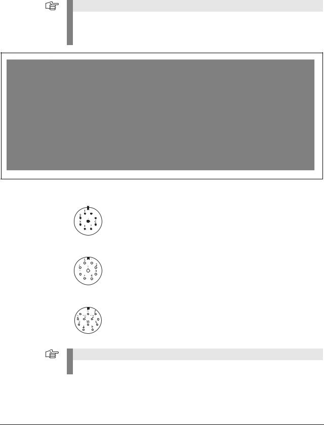
4.1Incremental interfaces
Determine interface from encoder designation
Note
The identification of the interface type applies to standard HEIDENHAIN encoders.
Deviations from the designation structure are possible (in particular with customer-specific encoders).
Other identifiers
A 9-pin M23 connector always means an 11 µApp interface.
Encoders connected to the encoder inputs of EXE interpolation electronics are always 11 µApp encoders.
Encoders connected to the encoder inputs of IBV interpolation electronics are always 1 Vpp encoders.
Note
For encoders with D-sub connectors no conclusions can be made about the interfaces.
November 2014 |
Identifying encoder output signals (encoder interfaces) |
25 |

4.2Absolute interfaces
Encoders that have a 'C' or a 'Q' in their names use an absolute interface (EnDat or SSI).
There are EnDat encoders with and without incremental A/B sinusoidal signals.
The order designation indicates whether an encoder outputs incremental signals:
EnDat 21 |
without incremental signals |
EnDat 22 |
without incremental signals |
EnDat 01 |
with incremental signals A/B 1 Vpp |
EnDat 02 |
with incremental signals A/B 1 Vpp |
EnDat Hx |
with incremental signals HTL (as of 2014) |
EnDat Tx |
with incremental signals TTL (as of 2014) |
x designates: a = 2-fold interpolation b = without interpolation c = scanning signals x2
Also see "Interfaces of HEIDENHAIN Encoders“ brochure, ID 1078628-xx.
26 |
HEIDENHAIN ATS Software User's Manual |

5 Software description
5.1Operational design
The ATS software runs by a dynamic context menu. The function menu contains the function groups that are available for the connected encoder. Depending on the encoder, the supported function groups / functions are displayed.
Example:
LC 183 encoder connected and activated.
Function group "Diagnostics" with two active functions ("Absolute-incremental deviation" and "Online diagnostics").
Explanation of the display
1Selected function pointer (< )
2Function group
3Function
4Connected encoder
5ID number
6Power supply symbol:
Encoder power supply OFF (green)
Encoder power supply ON (red)
November 2014 |
Software description |
27 |

5.2Setting up a connection to the encoder
Connect the encoder to the test unit with an adapter cable.
Note |
Adapter cables: See User's Manual "PWM 20 Cable and Connection Technology".
This User's Manual can be downloaded from the HEIDENHAIN website, see:
www.heidenhain.de/Documentation and Information/Software/Download Area/Diagnostic
Set/PWM/Documentation.
Double-click "Connect encoder" in the ATS main menu.
The "Encoder selection" window offers two possibilities of powering the encoder and setting the encoder interface:
1Automatic encoder identification by entering the ID of the encoder (mandatory for absolute encoders)
2The manual settings are only used, if no encoder ID is available (ID plate missing or illegible; encoder not in the ATS encoder database).
28 |
HEIDENHAIN ATS Software User's Manual |

3Select "Use power supply from subsequent electronics", if the PWM 20 is in feed-through mode and supposed to be powered from the subsequent electronics.
Exception: Do not set the checkmark for the feed-trough mode with SA 100 / SA 110! The subsequent electronics cannot supply power due to the potential segregation of the SA 100 / SA 110.
The PWM is powered by the subsequent electronics. (PWM 20 in feed-through mode)
Note
"Use power supply from subsequent electronics" is only required for the feed-through mode of the PWM 20. This means that the checkmark may only be set, if the PWM 20 is connected to the control loop between the control and the encoder (closed loop; X2 OUT connected to subsequent electronics) without an SA 100 / SA 110.
Note
HEIDENHAIN recommends automatic connection by entering the ID number. Automatic connection through entering the encoder ID is mandatory for feed-through mode at axes with absolute encoders!
The relevant encoder data is read from a database. This database is part of the ATS software.
The encoder database contains all ID numbers and variants of the encoders that existed when the ATS software was released.
The database is updated about every six months.
You will find the most recent data at www.heidenhain.de.
DANGER
If the manual setting of the encoder parameters does not match the connected encoder, the encoder, the IK 215, the PWM 20 or the computer may be damaged.
Note
For the encoder data, please refer to the respective mounting instructions or machine documentation. Contact the machine manufacturer or the HEIDENHAIN Service.
Encoder connection
Please ensure that the correct supply voltage is selected to avoid damage to the encoder. The cable between the encoder and the PWM 20 must not be connected or disconnected while under power. Otherwise the encoder and the PWM 20 might be damaged.
Check whether the cable between the encoder and the PWM 20 is correctly wired.
The pin layout of the encoder is included in the specifications. The pin layouts of the connecting cables are described in the catalog. An incorrectly wired connecting cable might damage the encoder and the PWM 20.
November 2014 |
Software description |
29 |

5.2.1 Feed-through mode
"´Feed-through" mode means connecting the PWM 20 into the control loop of an NC-controlled machine.
For diagnosing, the PWM 20 can be integrated into the control loop of an NC controlled machine tool via adapter cables at the encoder input X1 and the encoder output X2.
For the feed-through mode the power supply must be switched to the subsequent electronics in the ATS software.
Set the checkmark in feed-through mode only.
If no subsequent electronics is connected, the encoder is not powered (error message).
The feed-through mode is supported as of the software version 2.6. We recommend always using the most recent software version (see www.heidenhain.de).
The feed-through mode cannot be used for all interfaces supported by the ATS.
In principle, the following interfaces allow for feed-through mode:
EnDat, Fanuc, Mitsubishi, 1 Vpp, TTL, 11 µApp
EnDat/Fanuc/Mitsubishi
Metallic isolation is possible with the service adapters SA 100 and SA 110.
No metallic isolation, if the measurement is conducted with the PWM 20 only.
For encoders that also support incremental signals, the incremental signals can now also be displayed and evaluated.
EnDat 2.1
Normally, the only communication over the EnDat interface takes place during the start-up stage of the NC (interrogation and transfer of the absolute position data):
"Listening in" on the EnDat communication is not possible. (The synchronization time is too short for the PWM 20.)
The 1 Vpp signals A and B can be displayed.
Note
SIEMENS NC controls currently use EnDat 2.1 with A/B signals and do not support the monitor function!
30 |
HEIDENHAIN ATS Software User's Manual |

EnDat 2.2
Communication takes place continuously. However, there is no prescribed communication pattern. Instead, every OEM determines the sequence of EnDat communication on his own.
No universal “listening in” on the communication is possible.
The monitor function is only possible, if the valuation numbers for online diagnosis are included in data transfer. (The following controls support the monitor function: TNC 620, TNC 640, iTNC 530 [as of NC-SW 34049x-04], iTNC 530 HSCI with diagnostic function and DRIVE-DIAG.)
Synchronization with communication may take some time.
1 Vpp
No metallic isolation, if the measurement is conducted with the PWM 20 only.
Metallic isolation is possible with the SA 100.
The PWM 20 picks off the signals; without 120-ohm signal termination.
The limit frequency is influenced by the test setup (adapter cable, etc.)
11 µApp
The line is interrupted in feed-through mode, i.e. the PWM 20 has an 11 µApp receiver and reproduces the (emulated) input signals at the 11 µApp output.
The limit frequency is influenced by the test setup (adapter cable, etc.)
Not yet approved for ATS V2.8. Signal errors may occur!
TTL
Without PWT switchover:
The PWM 20 picks off the RS-485 signals, i.e. a standard RS-485 receiver without 120-ohm termination is connected to the lines.
Note
Automatic connection through entering the encoder ID is mandatory for feed-through mode at axes with absolute encoders!
Incremental interfaces also permit manual connection by selecting the interface in feed-through mode.
If the feed-through mode is not used, absolute and incremental encoders can be connected manually.
However, automatic connection via the ID number is recommended!
DANGER
Testing cables for feed-through mode are not suitable for regular machine operation. Due to the great variety of machine designs and their grounding variants it is not possible to exhaustively test all testing cables.
It is absolutely necessary that you check the safe and proper function of the testing cables for every test situation!
Uncontrolled axis movements cannot be ruled out when working with testing devices and cables in feed-through mode.
Example for machine axes with absolute encoders:
Determine the encoder ID with the PWM 20 before feed-through operation (no axis movement required).
Automatic connection through entering the encoder ID is mandatory for feed-through mode at axes with absolute encoders. However, the ID is not known and the encoders are not visible under their covers.
The ATS software can read out and display the encoder ID.
November 2014 |
Software description |
31 |
Loading...