


Technical Manual
TNC 416
TNC 406
TNC 306
For the NC software types
286 18x up to version 04 (TNC 416)
280 62x up to version 10 (TNC 406)
260 03x up to version 16 (TNC 306)
260 05x up to version 16 (TNC 306)
March 2000
208 829-21 · 2.1 · 3/2000 · S · Printed in Germany · Subject to change without notice
(208 829-E8)

Preface
This Technical Manual is intended for manufacturers and distributors of machine tools. It contains all necessary information for assembly, electrical installation, commissioning and PLC-programming for the HEIDENHAIN TNC 406 and TNC 306 contouring controls.
Whenever HEIDENHAIN improves the hardware or software in these controls you will receive a free delivery of updated information. Please insert this updated information into your manual without delay. This will ensure that your manual always reflects the current revision level.
You can use excerpts from this manual for your machine documentation. Enlarging the manual format (17 cm x 24 cm) by a factor of 1.225 will produce pages in A4 format.
No documentation can be perfect. This manual undergoes continual change and will benefit from your impulses and suggestions for improvement. Please help us by letting us know your ideas.
DR. JOHANNES HEIDENHAIN GmbH
Department PE
PO Box 1260
D-83292 Traunreut
Germany
3/97 TNC 406/TNC 306

Contents Technical Manual TNC 416, TNC 406, TNC 306
Update Information No. 15 - 11
Introduction
Mounting and Electrical Installation
Machine Integration
Machine Parameters
Markers and Words
PLC Programming
Data interfaces
OEM Cycles
Appendix
Subject Index
1
2
3
4
5
6
7
8
9
10
11

Introduction — Contents
1 |
Hardware concept |
2-2 |
|
|
|
|
|
2 |
Technical data TNC 416/406/TNC 306 |
2-3 |
|
|
|
|
|
3 |
Software |
2-8 |
|
3.1 NC Software |
2-8 |
||
|
|
||
3.1.1 NC Software number |
2-8 |
||
|
|
|
|
3.1.2 |
Software types and hardware |
2-9 |
|
|
|
|
|
3.1.3 |
Software releases |
2-9 |
|
|
|
|
|
3.2 |
PLC Software |
2-10 |
|
|
|
|
|
3.3. |
EPROM sockets |
2-11 |
|
3/2000 |
TNC 416/TNC 406/TNC 306 |
Hardware concept |
2-1 |
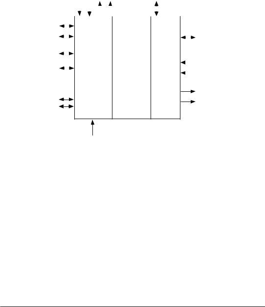
1 Hardware concept
The HEIDENHAIN TNC 416/TNC 406/TNC 306 controls are designed for ram-type electrical discharge machines.
The TNCs consists of several different assemblies. The main component is the logic unit. The logic unit is connected to the other assemblies and to peripheral equipment by means of connecting cables.
|
|
|
|
|
|
|
Nominal value |
|
|
|
|
|
|
|||
|
|
Encoders |
outputs |
|
PLC I/0 unit |
|
|
|
|
|||||||
|
|
|
|
|
|
● ● ● |
|
● ● ● |
|
|
|
|
|
|
|
|
|
|
|
|
|
|
|
|
|
|
|
|
|
|
|
||
|
|
|
|
|
|
|
|
|
|
|
|
|
|
|
||
Visual display unit |
|
|
|
|
|
|
|
|
|
|
|
|
|
|
||
|
|
|
|
|
|
|
|
|
|
|
|
|
|
|
||
|
|
|
|
|
|
|
|
|
|
|
|
|
||||
|
|
|
|
|
|
|
|
|
|
|
|
|||||
TNC keyboard unit |
|
|
|
|
|
|
|
|
|
|
|
Machine operating panel |
||||
|
|
|
|
|
|
|
|
|
|
|||||||
|
|
|
|
|
|
|
|
|
||||||||
Short circuit/ |
|
|
|
|
|
|
|
|
|
|
||||||
touch probe |
|
|
NC |
Common |
|
PLC |
|
|
|
PLC inputs |
||||||
Electronic handwheel |
|
|
|
|
|
|
|
|
|
|||||||
|
|
|
|
|
|
|
● |
|||||||||
|
|
data area |
|
|
● |
|||||||||||
|
|
|
||||||||||||||
|
|
|
|
|
|
|
|
|
|
|
|
|
● |
|
||
●
Data interfaces ● PLC outputs
●
Analogue input for gap control
The logic unit contains the circuitry for both the NC and the PLC sections of the control. The common data area contains the machine parameters, PLC markers and words. The machine parameters define the machine hardware configuration (traverse ranges, acceleration, number of axes, etc.). The PLC markers and words are used for the exchange of information between the NC and the PLC.
2-2 |
TNC 416/TNC 406/TNC 306 |
Hardware concept |
3/2000 |

2 Technical data TNC 416/TNC 406/TNC 306
|
TNC 416/TNC 406 |
TNC 306 |
|||
|
|
|
|
||
Components |
LE 406: |
• |
LE 360C logic unit |
||
• |
LE 406 logic unit |
• |
TE 355 keyboard unit |
||
|
|||||
|
• |
TE 400 keyboard unit |
• |
BF 110 mono chrome flat |
|
|
• |
BC 110 14“ color CRT |
or |
screen (192 x 120mm) |
|
|
|
640 x 400 pixels |
|
||
|
LE 416: |
• |
BE 212 12“ monochrome |
||
|
|
CRT 512 x 256 pixels |
|||
|
• |
LE 416 logic unit |
|
||
•TE 420 keyboard unit
•BF120 color flat screen 10,4“
or
•BC 120 15“ color CRT 640 x 480 pixels
Control type |
• |
Contouring control for 5 axes |
• |
Contouring control for 4 axes |
|
with eroding gap control |
|
with eroding gap control |
|
|
|
|
||
|
• |
Linear interpolation in 3 out of |
• |
Linear interpolation in 3 out of |
|
|
5 axes |
|
4 axes |
|
• |
Circular interpolation in 2 out |
• |
Circular interpolation in 2 out of |
|
|
of 4 axes |
|
4 axes |
|
• |
Helical interpolation with |
• |
Helical interpolation with |
|
|
simultaneous C-axis motion |
|
simultaneous C-axis motion |
|
|
|
|
|
Program memory |
|
10 000 program blocks |
5000 program blocks |
|
|
|
for up to 100 files |
for up to 32 files |
|
(NC programs, EDM parameters tables, one datum shift table) PLC program (if not contained in EPROM)
EPROM 128 Kbytes for PLC program, user cycles, EDM parameter tables, dialogs for user cycles, PLC error messages
3/2000 |
TNC 416/TNC 406/TNC 306 |
Technical data TNC 416/TNC 406/TNC 306 |
2-3 |

|
TNC 416/TNC 406 |
TNC 306 |
|
|
|
|
|
|
|
Operating modes |
• |
Manual |
|
|
• |
Electronic handwheel |
|
|
|
|
|
|
||
|
• |
Jog positioning |
|
|
|
• |
Positioning with MDI |
|
|
|
• |
Program run, single block |
|
|
|
• |
Program run, full sequence |
|
|
|
• |
Programming and editing |
|
|
|
• |
Test run (logical and graphical) |
|
|
|
|
|
|
|
Program input |
• |
In HEIDENHAIN plain language format |
|
|
• |
Manually on keyboard |
|
|
|
|
|
|
||
|
• |
Externally over data interface |
|
|
|
|
|
|
|
Input resolution |
1 µm |
|
|
|
|
|
|
|
|
display resolution |
0,1 µm |
1 µm |
|
|
|
|
|
|
|
Programmable functions |
• |
Nominal position (absolute or incremental) in Cartesian or polar |
|
|
|
coordinates |
|
|
|
|
|
|
|
|
|
• |
Linear path in 3 out of 4 axes |
|
|
|
• |
Circular path in 2 out of 4 axes |
|
|
|
• |
Helical path with simultaneous C-axis motion |
|
|
|
• |
Corner rounding, chamfer |
|
|
|
• |
Tangential contour approach and departure |
|
|
|
• |
Tool number and length, radius compensation, tool undersize |
|
|
|
• |
Spindle speed for axis C |
|
|
|
• |
Rapid traverse |
|
|
|
• |
Feed rate |
|
|
|
• |
Insertion of programs into other programs |
|
|
|
• |
Subprograms and program section repeats |
|
|
|
• |
Fixed cycles: disk pocket, EDM polishing, tool definition, |
|
|
|
|
generator definition |
|
|
|
• |
Datum shift, coordinate system rotation, mirror image, scaling |
|
|
|
• |
Dwell time, miscellaneous functions M, program stop |
|
|
|
• |
Remote control via LSV2 protocol (only TNC 416/406) |
|
|
|
|
|
|
|
2-4 |
TNC 416/TNC 406/TNC 306 |
Technical data TNC 416/TNC 406/TNC 306 |
3/2000 |

|
TNC 416/TNC 406 |
TNC 306 |
|
||||
|
|
|
|
|
|
|
|
|
• |
Mathematical functions (=, +, –, |
× |
, , sin, cos, |
|||
Parameter programming |
|
|
÷ |
______ |
|
||
|
angle α from r * sin α and r * cos α, √, √a² + b²; |
||||||
|
|
||||||
|
• |
variable parameter comparison (=,≠,>,<) |
|||||
|
• |
indexed data assignment |
|
|
|
|
|
|
output of parameter values over RS-232-C data interface |
||||||
|
|
|
|
|
|
|
|
Maximum traverse range |
± 30 000 mm (1181 in.) |
|
|
|
|
|
|
|
|
|
|
|
|
|
|
Maximum traverse speed |
30 m/min (1181 ipm) |
|
|
|
|
|
|
|
|
|
|
|
|
|
|
Data interface |
RS-232-C./.V.24 |
|
|
|
|
|
|
|
Baud rate 38 000; 19 200; 9600; 4800; 2400; 1200; 600; 300; 150; 110 |
||||||
|
|
|
|
|
|
|
|
|
RS-422 / V.11 (assigned to PLC) |
|
|
|
|
|
|
|
|
|
|
|
|
|
|
Cycle times |
|
|
|
|
|
|
|
Block processing time |
15 ms |
60 ms |
(with 2000 logical PLC |
||||
|
|
|
|
|
|
commands) |
|
Closed-loop cycle time |
2 / 4 ms (selected with MP) |
4 ms |
|
|
|||
PLC cycle time |
20 / 40 ms (selected with MP) |
40 ms |
|
|
|||
|
|
|
|
|
|
|
|
3/2000 |
TNC 416/TNC 406/TNC 306 |
Technical data TNC 416/TNC 406/TNC 306 |
2-5 |

|
TNC 416/TNC 406 |
TNC 306 |
|
|
|
Encoders |
HEIDENHAIN incremental linear encoders, optionally with distance- |
|
|
coded reference marks, grating period 0.01/0.02/0.1 mm (or rotary |
|
encoders)
Control inputs |
LE 406: |
|
6 encoder inputs (4 sinusoidal, |
||
|
||
|
2 square-wave inputs) |
|
|
LE 416: |
|
|
5 sinusoidal encoder inputs |
|
|
1 analog input for eroding gap |
|
|
signal |
|
|
1 input for electronic handwheel |
|
|
1 input for short circuit |
|
|
detection |
|
|
56 PLC inputs + 1 input for |
|
|
EMERGENCY STOP signal |
|
|
Additional 64 PLC inputs on |
|
|
PLC board PL 410 B (optional) |
5 encoder inputs (4 sinusoidal,
1 square-wave input)
1 analog input for eroding gap signal
1 input for electronic handwheel
1 input for short circuit detection
55 PLC inputs + 1 input for EMERGENCY STOP signal
Additional 64 PLC inputs on PLC board PL 410 B (optional)
Control outputs |
5 analog outputs for axes |
4 analog outputs for axes |
|
31 PLC outputs |
|
|
Additional 31 PLC outputs on PLC board PL 410 B (optional) |
|
|
|
|
Integral PLC |
Programming according to instruction list, 4000 PLC commands |
|
|
(Entry on HEIDENHAIN keyboard or over data interface) |
|
|
|
|
Power supply for LE |
24 Vdc |
|
|
|
|
2-6 |
TNC 416/TNC 406/TNC 306 |
Technical data TNC 416/TNC 406/TNC 306 |
3/2000 |

|
TNC 416/TNC 406 |
TNC 306 |
|||
|
|
|
|
|
|
Power consumption |
NC: |
6W |
|
NC: |
27 W (approx.) with |
|
PLC: |
6W |
|
|
BE 212 |
|
BC110: |
70W |
|
BF 110: 33 W |
|
|
BC120: |
80W |
|
|
|
|
BF 120: |
15W |
|
|
|
|
PL 410 B: 25 W (approx.) |
P L C : |
2 4 W (approx.) |
||
|
|
|
|
||
Ambient temperature |
Operation: |
0 to 45° C |
(BF 110: 0 to 40° C) |
||
|
Storage: |
|
–30 to 70° C |
|
|
|
|
|
|
|
|
Weight |
LE 416 |
6 kg |
|
LE 360C |
8 kg |
|
LE 406 |
8.5 kg |
TE 355 |
1.6 kg |
|
|
TE 400 |
2.4 kg |
BF 110 |
1.7 kg |
|
|
BC 110 |
11 kg |
|
BE 212 |
11 kg |
|
BC 120 |
14 kg |
|
PL 410 B |
1.5 kg |
|
BF 120 |
3 kg |
|
|
|
|
PL 410 B 1.5 kg |
|
|
||
|
|
|
|
|
|
3/2000 |
TNC 416/TNC 406/TNC 306 |
Technical data TNC 416/TNC 406/TNC 306 |
2-7 |
3 Software
The logic unit contains separate software for the NC section and the PLC section.
The software is identified by an 8-digit number. After the control is switched on, the NC and
PLC software numbers are displayed on the screen. The software number can also be directly requested with the aid of the MOD function.
3.1 NC Software
3.1.1 NC Software number
The 8-digit NC software number identifies the control model, the dialog language (language of the country) and the software version.
|
|
2 8 6 1 8 x -01 |
Software type |
|
|
TNC 416 |
|
|
National language |
|
|
0= English |
1= English |
2= English |
German |
German |
German |
French |
Swedish |
Czech |
talian |
Finnish |
res. |
Software version |
|
|
|
|
2 8 0 6 2 x -01 |
Software type |
|
|
TNC 406 |
|
|
National language |
|
|
0= English |
1= English |
2= English |
German |
German |
German |
French |
Swedish |
Czech |
Italian |
Finnish |
res. |
Software version |
|
|
|
|
2 6 0 0 3 x -01 |
Software type |
|
|
TNC 306 |
|
|
National language |
|
|
0= English |
|
|
1= Czech |
|
|
2= French |
|
|
3= Italian |
|
|
Software version |
|
|
In addition to the above languages the TNC 306 can always use German, which may be selected via machine parameter MP7230.
2-8 |
TNC 416/TNC 406/TNC 306 |
Software |
3/2000 |

3.1.2 Software types and hardware
HEIDENHAIN has up to now offered several different versions of the LE 360 and LE 360C logic units and a new LE 406. The following table shows which software type will run on which hardware version. Since the TNC 306 and TNC 406 are not subject to export restrictions, special export versions are not necessary.
Control |
|
Hardware Id.-Nr. |
Software type |
|
|
|
|
|
|
TNC 416 |
336 487 |
3x |
(for flat panel display BF) |
286 18x |
|
336 486 |
3x |
(for CRT color screen BC) |
|
|
|
|
|
|
|
|
|
|
|
TNC 406 |
|
|
288 513 15 |
280 62x |
|
|
|
|
|
TNC 306 for BE 212 |
|
|
264 085 96 |
260 03x |
TNC 306 C for BE 212 |
|
|
270 641 25 |
260 03x |
TNC 306 C for BF 110 |
|
|
270 642 25 |
260 05x |
3.1.3 Software releases
New NC software versions are periodically released by HEIDENHAIN.
Software version |
Release date |
|
|
TNC 416 |
3/99 |
286 18x-01 |
|
286 18x-02 |
4/99 |
286 18x-03 |
4/99 |
286 18x-04 |
2/2000 |
|
|
Software version |
Release date |
|
|
TNC 406 |
3/94 |
280 62x-01 |
|
280 62x-02 |
10/94 |
280 62x-03 |
11/95 |
280 62x-04 |
11/96 |
280 62x-05 |
2/97 |
280 62x-06 |
10/98 |
280 62x-07 |
12/98 |
280 62x-08 |
3/99 |
280 62x-09 |
12/99 |
280 62x-10 |
2/2000 |
|
|
3/2000 |
TNC 416/TNC 406/TNC 306 |
Software |
2-9 |

Software version |
Release date |
Software version |
Release date |
TNC 306 |
|
TNC 306 |
|
260 03x-03 |
2/92 |
260 05x-03 |
2/92 |
260 03x-04 |
3/93 |
260 05x-04 |
3/93 |
260 03x-05 |
8/93 |
260 05x-05 |
8/93 |
260 03x-06 |
11/93 |
260 05x-06 |
11/93 |
260 03x-07 |
3/94 |
260 05x-07 |
3/94 |
260 03x-08 |
6/94 |
260 05x-08 |
6/94 |
260 03x-09 |
6/94 |
260 05x-09 |
6/94 |
260 03x-10 |
11/94 |
260 05x-10 |
11/94 |
260 03x-11 |
2/95 |
260 05x-11 |
2/95 |
260 03x-12 |
6/95 |
260 05x-12 |
6/95 |
260 03x-13 |
11/95 |
260 05x-13 |
11/95 |
260 03x-14 |
2/96 |
260 05x-14 |
2/96 |
260 03x-15 |
11/96 |
260 05x-15 |
11/96 |
260 03x-16 |
1/97 |
260 05x-16 |
1/97 |
|
|
|
|
3.2 PLC Software
The PLC software is produced by the machine manufacturer. Either HEIDENHAIN or the machine manufacturer can store this software in EPROMs. HEIDENHAIN assigns PLC software numbers to the machine manufacturers on request. HEIDENHAIN can archive the specific PLC programs in a database, so that the installation of the correct PLC program is assured if a control has to be exchanged.
2-10 |
TNC 416/TNC 406/TNC 306 |
Software |
3/2000 |
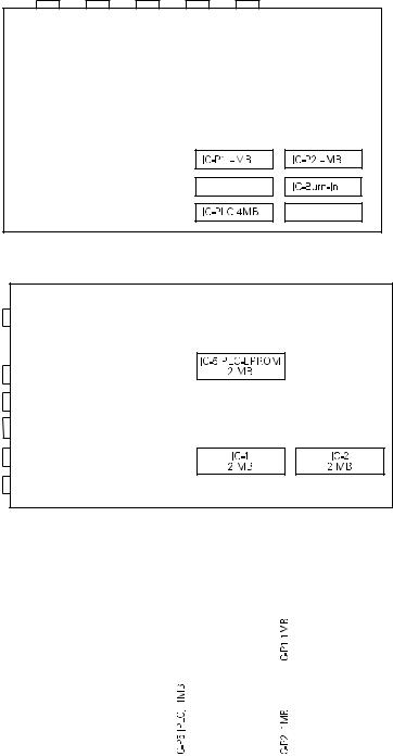
3.3 EPROM sockets EPROM sockets LE 416
EPROM sockets LE 406
EPROM sockets LE 306
|
|
|
|
|
|
|
|
|
|
|
|
|
|
|
|
|
|
|
|
|
|
|
|
|
|
|
|
|
|
|
|
|
|
|
|
|
|
|
|
|
|
|
|
|
|
|
|
|
|
|
|
|
|
|
|
|
|
|
|
|
|
|
|
|
|
|
|
|
|
|
|
|
|
|
|
|
|
|
|
|
|
|
|
|
|
|
|
|
|
|
|
|
|
|
|
|
|
|
|
|
|
|
|
|
|
|
|
|
|
|
|
|
|
|
|
|
|
|
|
|
|
|
|
|
|
|
|
|
|
|
|
|
|
|
|
|
|
|
|
|
|
|
|
|
|
|
|
|
|
|
|
|
|
|
|
|
|
|
|
|
|
|
|
|
|
|
|
|
|
|
|
|
|
|
|
|
|
|
|
|
|
|
|
|
|
|
|
|
|
|
|
|
|
|
|
|
|
|
|
|
|
|
|
|
|
|
|
|
|
|
|
|
|
|
|
|
|
|
|
|
|
|
|
|
|
|
|
|
|
|
|
|
|
3/2000 |
TNC 416/TNC 406/TNC 306 |
Software |
2-11 |
|||||||||

Danger of electrical shock!
Unplug the power cord before opening the housing.
Danger to internal components!
When handling components that can be damaged by electrostatic discharge (ESD), observe the safety recommendations in DIN EN 100 015. Use only antistatic packaging material. Be sure that the work station and the technician are properly grounded during installation.
2-12 |
TNC 416/TNC 406/TNC 306 |
Software |
3/2000 |

Mounting and electrical installation — Contents
1 Hardware components |
3–4 |
|
1.1 |
Components of the TNC 416 |
3–4 |
1.2 |
Components of the TNC 406 |
3–4 |
1.3 |
Components of the TNC 306 |
3–4 |
|
|
|
1.4 |
Options |
3–4 |
|
|
|
2 Installation |
3–6 |
|
2.1 |
Electrical noise immunity |
3–6 |
2.2 |
Heat generation and cooling |
3–7 |
|
|
|
2.3 |
Humidity |
3–8 |
|
|
|
2.4 |
Mechanical vibration |
3–8 |
2.5 |
Mounting position |
3–8 |
2.5.1 |
Logic unit |
3–9 |
|
|
|
2.5.2 |
Visual display unit |
3–12 |
|
|
|
2.5.3 |
PLC Input/Output board PL 410 B |
3–12 |
2.6 |
Degree of protection |
3–12 |
|
|
|
3 Overview of connections |
3–13 |
|
|
|
|
4 Power supply |
3–17 |
|
4.1 |
Overview |
3–17 |
4.1.1 |
NC power supply |
3–18 |
|
|
|
4.1.2 |
PLC power supply |
3–19 |
4.1.3 |
Buffer battery |
3–21 |
4.2 |
Power supply for the visual display unit |
3–22 |
4.3 |
Grounding plans |
3–24 |
|
|
|
4.3.1 |
Grounding plan TNC 416 |
3–24 |
4.3.2 |
Grounding plan TNC 406 |
3–25 |
4.3.3 |
Grounding plan TNC 306 |
3–26 |
|
|
|
5 Measuring systems |
3–29 |
|
5.1 |
Linear measuring systems |
3–29 |
|
|
|
5.2 |
Angular measuring systems |
3–29 |
5.3 |
Measuring system inputs for sinusoidal signals |
3–30 |
5.3.1 |
Connector assignments |
3–30 |
|
|
|
5.4 |
Measuring system input for square-wave signals |
3–32 |
|
|
|
5.4.1 |
Connector assignments |
3–32 |
|
|
|
6 Nominal value output / Gap signal input |
3–33 |
|
6.1 |
Connector assignment |
3–34 |
|
|
|
7 Visual display unit (VDU) |
3–37 |
|
7.1 |
Connector assignment |
3–37 |
3/99 |
TNC 416/TNC 406/TNC 306 |
Hardware components |
3–1 |

8 Short-circuit signal/Touch probe input |
3–40 |
||
8.1 |
|
Connection of the short-circuit signals |
3–41 |
8.2 |
|
Connection of the touch probe system |
3–41 |
|
|
||
9 Data interface |
3–43 |
||
9.1 |
|
RS-232-C/V.24 data interface |
3–43 |
|
|
|
|
9.2 |
|
RS 422/V.11 data interface |
3–44 |
|
|
|
|
10 |
Handwheel input |
3–45 |
|
10.1 |
Portable handwheel HR 410 |
3–45 |
|
10.2 |
Panel-mounted handwheel HR 130 |
3–48 |
|
|
|
|
|
11 |
PLC inputs/outputs |
3–50 |
|
11.1 |
Technical data |
3–50 |
|
|
|
|
|
11.2 |
Connector assignment |
3–51 |
|
11.2.1 PLC output |
3–52 |
||
11.3 |
PLC I/O expansion board PL 410 B |
3–54 |
|
|
|
||
11.3.1 PLC inputs/PLC outputs on the PL 410 B |
3–55 |
||
|
|
|
|
12 |
Machine control panel |
3–58 |
|
|
|
|
|
13 |
TNC keyboard |
3–60 |
|
|
|
|
|
14 |
Cable overview |
3–62 |
|
14.1 |
Cable overview TNC 416 |
3–62 |
|
|
|
|
|
14.2 |
Cable overview TNC 406 |
3–63 |
|
14.3 |
Cable overview TNC 306 |
3–64 |
|
3–2 |
TNC 416/TNC 406/TNC 306 |
Hardware components |
3/99 |

15 Mounting dimensions |
3–66 |
||
15.1 |
LE 416 |
3–66 |
|
15.2 |
LE 406 |
3–67 |
|
15.3 |
TE 420 |
3–68 |
|
15.4 |
TE 400 |
3–69 |
|
|
|
|
|
15.5 |
BC 120 |
3–70 |
|
15.6 |
BF 120 |
3–71 |
|
15.7 |
BC 110 B |
3–72 |
|
15.7.1 |
LE 360 C |
3–73 |
|
|
|
|
|
15.8 |
Keyboards for TNC 306 |
3–74 |
|
15.8.1 |
TE 355 A |
3–74 |
|
15.8.2 |
TE 355 B |
3–75 |
|
15.9 |
Visual display units for TNC 306 |
3–76 |
|
|
|
|
|
15.9.1 |
BE 212 |
3–76 |
|
15.9.2 |
BF 110 |
3–77 |
|
15.10 |
Input/Output boards PL 410B |
3–78 |
|
15.11 |
Handwheel HR |
3–79 |
|
|
|
|
|
15.11.1 |
Panel-mounted handwheel HR 130 |
3–79 |
|
15.11.2 |
Portable handwheels HR 410 |
3–83 |
|
15.11.3 |
Touchprobe system TS 220 |
3–83 |
|
15.12 |
Cable adapter |
3–84 |
|
|
|
|
|
3/99 |
TNC 416/TNC 406/TNC 306 |
Hardware components |
3–3 |

1 Hardware components
1.1 Components of the TNC 416
LE 416 Logic Unit for BC 120 |
Id.-Nr. 336 486-3x |
for BF 120 |
Id.-Nr. 336 487-3x |
TE 420 Keyboard Unit |
Id.-Nr. 313 038-01 |
BC 120 Visual Display Unit |
Id.-Nr. 313 037-01 |
(15-inch color monitor) |
|
BF 120 Visual Display Unit |
Id.-Nr. 313 506-01 |
(10.4-inch color flat panel display) |
|
1.2 Components of the TNC 406
LE 406 Logic |
Id.-Nr. 288 513-19 |
TE 400 Keyboard Unit |
Id.-Nr. 250 517-03 |
BC 110 B Visual Display Unit |
Id.-Nr. 260 520-01 |
(14-inch color monitor) |
|
1.3 Components of the TNC 306
LE 306 Logic Unit for BE 212 |
Id.-Nr. 270 641-2x |
for BF 110 |
Id.-Nr. 270 642-2x |
TE 355A Keyboard Unit |
Id.-Nr. 255 015-06 |
TE 355 B Keyboard Unit |
Id.-Nr. 255 016-04 |
BF 110 Visual Display Unit |
Id.-Nr. 267 209-01 |
(9-inch monochrome flat panel display) |
|
BE 212 Visual Display Unit |
Id.-Nr. 242 370-01 |
(12-inch monochrome monitor) |
|
1.4 Options |
|
PL 410 B PLC I/O board |
Id. Nr. 263 371-12 |
Handwheel HR 410 |
Id. Nr. 296 469-01 |
Touch Probe System TS 220 |
Id. Nr. 293 488-xx |
3–4 |
TNC 416/TNC 406/TNC 306 |
Hardware components |
3/99 |

3/99 |
TNC 416/TNC 406/TNC 306 |
Hardware components |
3–5 |
2 Installation
2.1 Electrical noise immunity
Please note that the vulnerability of electronic equipment to noise increases with faster signal processing rates and higher sensitivity. Please protect your equipment by observing the following rules and recommendations.
Noise voltages are mainly produced and transmitted by capacitive and inductive coupling. Electrical noise can be picked up by the inputs and outputs to the equipment, and by the cabling.
Possible sources of interference are:
–Strong magnetic fields from transformers and electric motors
–Relays, contactors and solenoid valves
–High-frequency equipment, pulse equipment and stray magnetic fields from switch-mode power supplies
–Mains leads and leads to the above equipment
Electrical interference can be avoided by:
–A minimum distance between the logic unit (and its leads) and interfering equipment > 20 cm.
–A minimum distance between the logic unit (and its leads) and cables carrying interference signals > 10 cm.
(Where signal cables and cables which carry interference signals are laid together in metallic ducting, adequate decoupling can be achieved by using a grounded separation shield)
–Screening according to DIN VDE 0160.
–Potential compensating lines ø 6 mm² (see grounding plan).
–Use of original HEIDENHAIN cables, connectors and couplings.
3–6 |
TNC 416/TNC 406/TNC 306 |
Installation |
3/99 |

2.2 Heat generation and cooling
Please note that the reliability of electronic equipment is greatly reduced by continuous operation at elevated temperatures. Please take the necessary measures to maintain the permissible ambient temperature range.
Permissible ambient temperature during operation: 0 to 45° C (BF 110: 0 to 40° C)
The following means may be employed to ensure adequate heat removal:
–Provide sufficient space for air circulation.
–Build in a ventilator fan to circulate the air inside the control cabinet. The fan must reinforce the natural convection. It must be mounted so that the warm air is extracted from the logic unit and no pre-warmed air is blown into the unit. The warm air should flow over surfaces
that have good thermal conductivity to the external surroundings (e.g. sheet metal).
–For a closed steel housing without assisted cooling, the figure for heat conduction is 3 watt/m² of surface per °C air temperature difference between inside and outside.
–Use a heat exchanger with separate internal and external circulation.
–Forced-air cooling by blowing external air through the control cabinet to replace the internal air. In this case the ventilator fan must be mounted so that the warm air is extracted from the control cabinet and only filtered air can be drawn in. HEIDENHAIN advises against this method of cooling, since the functioning and reliability of electronic assemblies are adversely affected by contaminated air (fine dust, vapors, etc.). In addition to these disadvantages, an inadequately serviced filter can lead to a loss in cooling efficiency. Regular servicing is therefore essential.
Incorrect |
|
Correct |
|
|
|
|
|
|
LE
Obstructive
elements
LE
Heat generating elements
|
|
|
|
|
|
|
|
|
|
|
|
3/99 |
TNC 416/TNC 406/TNC 306 |
Installation |
|
3–7 |
|

2.3 Humidity
Permissible humidity: |
< 75% in continuous operation, |
|
< 95% for not more than 30 days p.a. (randomly distributed). |
In tropical areas it is recommended that the TNC remain permanently switched on to prevent condensation on the circuit boards.
2.4 Mechanical vibration
Permissible vibration: |
< 5 m/s2; 0-500 Hz |
2.5 Mounting position
Note the following fundamental points on mounting:
–Mechanical accessibility
–Permissible environmental conditions
–Electrical noise immunity
–The electrical regulations which are in force in your country
3–8 |
TNC 416/TNC 406/TNC 306 |
Installation |
3/99 |

2.5.1 Logic unit
HEIDENHAIN recommends the following mounting position of LE 416

 5.91"
5.91"

 Air outlet

>3.54"

 >4.72"
 Air inlet
7.87"

 >3.54"
3/99 |
TNC 416/TNC 406/TNC 306 |
Installation |
3–9 |

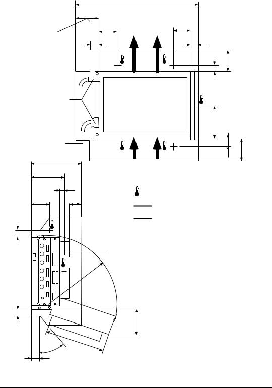
HEIDENHAIN recommends the following mounting position of LE 406
|
|
|
|
>577 |
|
|
|
|
|
|
|
>110 |
|
|
|
|
|
|
|
Minimum clearance |
|
80 |
|
|
|
80 |
|
|
|
for servicing! |
|
|
40 |
|
|
|
40 |
|
|
recommended: = |
|
|
|
|
|
|
|||
approx. 250 mm |
|
|
|
°C |
|
|
°C |
100 |
|
|
|
|
|
Air outlet |
|
||||
|
|
|
* |
|
|
|
* |
|
|
|
|
|
|
|
|
|
30 |
|
|
Maintain clearance |
|
|
|
|
|
°C |
|
|
|
for screwdriver |
|
|
|
|
|
|
|
|
|
|
|
|
|
|
|
|
* |
|
|
Connecting cables |
|
|
|
|
|
160 |
|
|
|
|
|
|
|
|
|
|
|
||
must not hinder |
|
|
|
|
|
|
|
|
|
swivel movement |
|
|
°C |
|
|
|
|
|
|
of the control |
|
|
* |
|
|
|
°C* |
30 |
100 |
|
246 |
|
|
Air inlet |
|||||
|
|
|
|
|
|
|
|
|
|
160 |
|
|
|
|
|
|
|
|
|
|
|
30 |
|
|
°C * |
Measuring point for |
|
|
|
|
|
|
|
|
ambient temperature |
|
|
||
83 |
|
60 |
|
|
|
Free space for air circulation |
|
||
|
|
|
|
|
|
|
|||
|
°C |
|
|
|
|
Free space for servicing |
|
|
|
|
|
|
|
|
|
|
|
|
|
40 |
* |
|
|
|
|
|
|
|
|
|
|
|
|
|
|
|
|
|
|
|
|
|
PL |
|
|
|
|
|
|
|
°C |
|
|
|
|
|
|
|
|
|
* |
R |
325 |
|
|
Illustration of |
|
|
|
|
|
|
|
max. swivel range. |
|
|
|||
|
|
|
|
|
|
|
|
||
|
|
|
|
|
|
The minimum angle of |
|
|
|
|
|
|
|
|
|
swivel for exchange |
|
|
|
|
|
|
|
|
|
of subassembly should |
|
|
|
|
|
|
|
|
|
be at least 90°. |
|
|
|
40 |
145 |
270 |
° |
40 |
40 |
3–10 |
TNC 416/TNC 406/TNC 306 |
Installation |
3/99 |
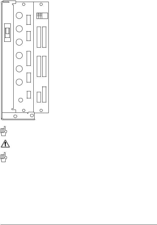
HEIDENHAIN recommends the following mounting position of LE 306
|
|
|
|
>577 |
|
|
|
|
|
|
>110 |
|
|
|
|
|
|
Minimum clearance |
|
80 |
|
|
80 |
|
|
|
for servicing! |
|
|
40 |
|
|
40 |
|
|
recommended:= |
|
|
|
|
|
|||
approx. 250 mm |
|
|
|
°C |
|
°C |
|
|
|
|
|
|
Air |
100 |
|
||
|
|
|
* |
|
* |
|
||
|
|
|
|
outlet |
|
|
||
|
|
|
|
|
|
30 |
|
|
Maintain clearance |
|
|
|
|
°C |
|
|
|
for screwdriver |
|
|
|
|
|
* |
|
|
|
|
|
|
|
|
|
|
|
|
|
|
|
|
|
160 |
|
|
Connecting cables |
|
|
|
|
|
|
|
|
must not hinder |
|
|
* |
°C |
|
°C* |
|
|
swivel movement |
|
Air |
|
100 |
||||
of the control |
218.5 |
|
|
|
inlet |
|
30 |
|
|
|
|
|
|
|
|
|
|
132.5 |
|
|
|
|
|
|
|
|
|
|
30 |
|
|
°C * |
Measuring point for |
|
|
|
|
|
|
|
ambient temperature |
|
|
|
83 |
|
60 |
|
|
|
Free space for air circulation |
|
|
|
|
|
|
|
|
|
||
|
°C |
|
|
|
|
Free space for servicing |
|
|
|
|
|
|
|
|
|
|
|
40 |
* |
|
|
|
|
|
|
|
|
|
|
|
|
|
|
|
|
|
|
|
PL |
|
|
|
|
|
|
°C |
|
|
|
|
|
|
|
|
* |
R |
325 |
|
|
Illustration of |
|
|
|
|
|
|
max. swivel range. |
|
|
||
|
|
|
|
|
|
|
|
|
|
|
|
|
|
|
The minimum angle of |
|
|
|
|
|
|
|
|
swivel for exchange |
|
|
|
|
|
|
|
|
of subassembly should |
|
|
|
|
|
|
|
|
be at least 90°. |
|
|
40 |
145 |
270 |
° |
40 |
40 |
3/99 |
TNC 416/TNC 406/TNC 306 |
Installation |
3–11 |

2.5.2 Visual display unit
Permissible ambient temperature: |
|
BC 120/BC 110/BE 212/BF 120: |
max. 45° C |
BF 110: |
max. 40° C |
The VDU must be installed with a minimum clearance of 25 mm to the housing. It is particularly recommended that a large area is left free above the unit for heat escape.
Temperature is measured at a distance of 25 mm to the housing. The above mentioned temperatures must not be exceeded.
When installing the BC 120/BC 110/BE 212, remember that this VDU is very sensitive to magnetic interference. The image position and geometry can be disturbed by stray magnetic fields; alternating fields can cause periodic movement or image distortion.
For this reason, keep a minimum distance of 0.5 m between the VDU housing and sources of interference (permanent magnets, motors, transformers, etc.)
2.5.3 PLC Input/Output board PL 410 B
One PL 410 B can be connected to the LE 406 or LE 360 C, if desired. There is no preferred mounting position for heat removal.
2.6 Degree of protection
Visual display unit when mounted Keyboard unit when mounted HR 410 handwheel
Protection class IP54 Protection class IP54 Protection class IP54
IP54 = Protection against dust and splashwater
3–12 |
TNC 416/TNC 406/TNC 306 |
Installation |
3/99 |

3 Overview of connections
LE 416
X1 Measuring system 1 (1Vss/11µA)
X2 Measuring system 2 (1Vss/11µA)
X3 Measuring system 3 (1Vss/11µA)
X4 Measuring system 4 (1Vss/11µA)
X6 Measuring system 5 (1Vss/11µA)
X8 Nominal value outputs 1,2,3,4,5, gap signal input
X12 Triggering touch probe for workpiece measurement
X13 Triggering touch probe for tool measurement
X21 RS-232-C/V24 data interface
X22 RS-422/V11 data interface
X23 Handwheel interface
X41 PLC output
X42 PLC input
X43 BC 120 VDU (alternative to BF 120)
X44 PLC power supply
X45 TNC keyboard
X46 Machine operating panel
X47 PLC expansion
X48 PLC analog input
X49 BF 120 flat panel (alternative to BC
120)
X31 NC power supply
X13, X30 Do not use
X65 not installed
B Signal ground
Protective ground (YL/GN)
Interfaces X1, X2, X3, X4, X6, X8, X12, X21, X22, X23, X41, X42, X43, X45, X46, X47, X49 comply with the recommendations in VDE 0160, 5. 88 for separation from line power.
Danger to internal components!
Do not engage or disengage any connections while the unit is under power.
The outputs at connection X.... (indicate pin number if appropriate) are metallically isolated from the device electronics by means of optocouplers.
3/99 |
TNC 416/TNC 406/TNC 306 |
Overview of connections |
3–13 |
LE 406
X1 |
X12 |
X44 |
|
||
|
|
|
X2 |
|
X41 X45 |
24V |
X8 |
|
|
|
|
X3 |
|
|
X31 |
|
|
X4 |
X21 |
X42 X46 |
|
|
|
X5 |
|
|
|
X22 |
|
X6 |
|
|
|
|
X47 |
|
X23 |
X43 |
B
X1 Measuring system 1 (11µA)
X2 Measuring system 2 (11µA)
X3 Measuring system 3 (11µA)
X4 Measuring system 4 (11µA)
X5 Measuring system 5 ( 

 )
)
X6 Measuring system 6 ( 

 )
)
X8 Nominal value outputs 1,2,3,4,5 gap signal input
X12 Touch probe system;
Short-circuit signal input
X21 Data interface RS-232-C/V.24
X22 Data interface RS-422/V.11
X23 Electronic handwheel HR 130/HR 410
X41 PLC output
X42 PLC input
X43 VDU BC 110
X45 TNC keyboard TE 400
X46 Machine operating panel
X47 PLC I/O board PL 410 B
X31 Power supply 24 V for NC
X44 Power supply 24 V for PLC
B Signal ground
Interfaces X1, X2, X3, X4, X5, X6, X8, X12, X21, X22, X23, X41, X42, X43, X45, X46 and X47 comply with the recommendations in VDE 0160, 5. 88 for separation from line power.
Danger to internal components!
Do not engage or disengage any connections while the unit is under power.
The outputs at connection X.... (indicate pin number if appropriate) are metallically isolated from the device electronics by means of optocouplers.
3–14 |
TNC 416/TNC 406/TNC 306 |
Overview of connections |
3/99 |

LE 306
X1
|
X11 |
X21 X24 |
|
|
|
||
X2 |
|
|
|
24V |
X12 |
|
|
|
X25 |
||
|
|
||
X3 |
|
|
|
X31 |
|
|
|
X4 |
X8 |
X22 |
|
X26 |
|||
|
|
X6 |
X23 X27 |
|
X9 |
B
X1 Measuring system 1 (11µA)
X2 Measuring system 2 (11µA)
X3 Measuring system 3 (11µA)
X4 Measuring system 4 (11µA)
X6 Measuring system ( 

 )
)
X8 Nominal value outputs 1,2,3,4; gap signal input
X9 VDU BE212/BF110
X11 Electronic handwheel HR 130/HR 410
X12 Touch probe system
Short-circuit signal input
X21 PLC output
X22 PLC input
X23 TNC keyboard TE355
X25 Data interface RS-232-C/V.24
X26 PLC I/O board PL 410 B
X27 Machine operating panel
X31 Power supply 24 V for NC
X24 Power supply 24 V for PLC
B Signal ground
Interfaces X1, X2, X3, X4, X6, X8, X9, X11, X12, X21, X22, X23, X25, X26, and X27 comply with the recommendations in VDE 0160, 5. 88 for separation from line power.
Danger to internal components!
Do not engage or disengage any connections while the unit is under power.
The outputs at connection X.... (indicate pin number if appropriate) are metallically isolated from the device electronics by means of optocouplers.
3/99 |
TNC 416/TNC 406/TNC 306 |
Overview of connections |
3–15 |
 Loading...