


Technical Information
˜
˜ ˜••¬˜ ˜
˜
NC Software 286 02x xx
z•ad˜snnn˜

Contents
1 |
Specifications |
1–1 |
2 |
Components |
2–4 |
3 |
Mounting and Electrical Installation |
3–6 |
3.1 |
Electrical Noise Immunity |
3–6 |
|
|
|
3.2 |
Heat Generation and Cooling |
3–7 |
|
|
|
3.3 |
Humidity |
3–7 |
3.4 |
Mechanical Vibration |
3–7 |
3.5 |
Degree of Protection |
3–7 |
|
|
|
3.6 |
Mounting Position |
3–8 |
|
|
|
3.7 |
Connection Overview |
3–10 |
3.7.1 |
LE 370 D |
3–10 |
3.7.2 |
Power Supply |
3–11 |
3.7.3 |
Measuring System Inputs |
3–13 |
|
|
|
3.7.4 |
Reference Signal for the Spindle |
3–14 |
3.7.5 |
Supply voltage for "Control-is-ready" |
3–14 |
3.7.6 |
Analog Nominal Value Output |
3–15 |
3.7.7 |
Switching Inputs 24 Vdc for the PLC |
3–17 |
|
|
|
3.7.8 |
Switching Outputs 24 Vdc for the PLC |
3–20 |
3.7.9 |
Machine Operating Panel |
3–23 |
3.7.10 |
TNC Keyboard |
3–24 |
3.7.11 |
Visual Display Unit |
3–26 |
|
|
|
3.7.12 |
PLC input/output unit PL 410 B/ PL 405 B |
3–27 |
3.7.13 |
Touch Trigger Probes |
3–28 |
3.7.14 |
RS-232-C/V.24 Data Interface |
3–31 |
3.7.15 |
Handwheel Input |
3–32 |
|
|
|
3.7.16 |
Analog Inputs |
3–37 |
|
|
|
3.8 |
Visual Display Unit BF 370 B |
3–40 |
3.9 |
Mounting Dimensions |
3–41 |
3.10 |
Cable overview |
3–44 |
|
|
|
3.11 |
Grounding plan |
3–45 |
4.1 |
What Is a Machine Parameter? |
4–47 |
4.2 |
Input and Output of Machine Parameters |
4–48 |
|
|
|
4.2.1 |
Input Format |
4–48 |
4.2.2 |
Activating the Machine Parameter Settings |
4–48 |
4.2.3 |
Changing the Input Values |
4–49 |
4.3 |
List of Machine Parameters |
4–52 |
|
|
|
4.3.1 |
Encoders and Machine |
4–52 |
4.4 |
Positioning |
4–57 |
4.5 |
Operation with Velocity Feedforward |
4–59 |
4.6 |
Operation with Servo Lag |
4–60 |
|
|
|
4.7 |
Main Spindle |
4–60 |
|
|
|
4.8 |
Integrated PLC |
4–64 |
July 02 |
Specifications |
TNC 370 D |
1–1 |

4.9 |
Adaptation of the Data Interfaces |
4–66 |
4.10 |
3-D Touch Probe |
4–67 |
4.11 |
Tool Measurement with TT 130 |
4–68 |
4.12 |
Tapping |
4–70 |
|
|
|
4.13 |
Display and Operation |
4–71 |
|
|
|
4.14 |
Machining and Program Run |
4–75 |
4.15 |
Hardware |
4–79 |
5 |
List of Markers and Words |
5–81 |
5.1 |
List of Markers |
5–81 |
5.2 |
List of Words |
5–85 |
6 |
List of Modules |
6–88 |
1–2 |
TNC 370 D |
Specifications |
July 02 |

1 Specifications
Axes |
3 or 4 and spindle S; |
||
|
|
All axes can be defined as NC or PLC axes |
|
|
|
|
|
Program memory |
128 KB (64 NC programs with a total of approx. 6000 blocks) |
||
|
|
|
|
Input resolution and |
1 µm for linear axes |
||
display step |
0.001 degrees for rotary axes |
||
|
|
|
|
Interpolation |
|
|
|
|
|
|
|
|
Linear interpolation |
3 of 4 axes |
|
|
|
|
|
|
Circular interpolation |
2 of 4 axes |
|
|
|
|
|
|
Helix |
Superimposition of circular arcs and straight lines |
|
|
|
|
|
|
Tapping without |
Yes |
|
|
floating tap holder1) |
|
|
Block processing time2) |
6 ms |
||
Axis control |
Velocity feedforward control; |
||
|
|
Operation with servo lag |
|
|
|
|
|
|
Position control |
Fehler! |
|
|
resolution |
|
|
|
|
|
|
|
Cycle time path |
6 ms |
|
|
interpolation |
|
|
|
|
|
|
Error compensation |
|
Linear axis error |
|
|
|
|
Multipoint axis error |
|
|
|
Backlash |
|
|
Reversal spikes during circular motion |
|
|
|
|
Thermal expansion |
|
|
|
Offset |
|
|
||
Data interface |
RS–232–C/ V.24, max. 115 200 baud |
||
|
|
|
|
1)This function must be implemented by the machine manufacturer.
2)3-D straight lines without radius compensation
July 02 |
Specifications |
TNC 370 D |
1–1 |

Integral PLC |
|
|
|
|
|
|
|
|
|
PLC memory |
Approx. 8 000 commands |
|
|
|
|||
|
|
|
|
|
|
|
|
|
|
PLC cycle time |
24 ms |
|
|
|
|
|
|
|
|
|
|
|
|
|
||
|
|
LE |
LE + PL 410 B |
LE + 2 PL 410 B |
||||
|
|
|
|
|
|
|
||
|
|
|
Analog input PT 100 |
Analog input PT 100 |
||||
|
|
|
without |
|
with |
without |
|
with |
|
|
|
|
|
||||
|
|
|
|
|
|
|
|
|
|
PLC inputs 24 Vdc |
56 |
119 |
|
119 |
183 |
|
183 |
|
|
|
|
|
|
|
|
|
|
PLC outputs 24 Vdc |
31 |
62 |
|
62 |
93 |
|
93 |
|
|
|
|
|
|
|
|
|
|
Analog inputs 10 V |
3 (option) |
– |
|
7 |
– |
|
11 |
|
|
|
|
|
|
|
|
|
|
Inputs for PT100 thermistors |
2 (option) |
– |
|
6 |
– |
|
10 |
|
|
|
|
|
|
|
|
|
|
"Control-is-ready" signal output |
1 |
2 |
|
|
3 |
|
|
|
|
|
|
|
|
|
|
|
|
"Control-is-ready" signal input |
1 |
1 |
|
|
1 |
|
|
|
|
|
|
|
|
|
|
|
Power supply for logic |
400 Vac 10 % |
|
|
|
|
|
||
Power supply for PLC |
24 Vdc |
|
|
|
|
|
|
|
|
|
|
|
|
|
|
|
|
Weight |
6 kg |
|
|
|
|
|
|
|
|
|
|
|
|
|
|
|
|
1–2 |
TNC 370 D |
Specifications |
July 02 |

User Functions
Program input |
In HEIDENHAIN conversational programming and according to ISO |
|
Position data |
Nominal positions in Cartesian or polar coordinates, dimensional data |
|
|
absolute or incremental, display and input in mm or inches |
|
|
|
|
Subprogramming |
Program section repeat, subprograms, program calls |
|
|
|
|
Parallel operation |
Creation of a program while another program is being run |
|
|
|
|
Fixed cycles |
Peck drilling, tapping, slot milling, rectangular and circular pockets, |
|
|
contour pockets |
|
|
OEM cycles |
|
|
|
|
Coordinate |
Shift, rotation, mirror, scaling (axis-specific) |
|
transformation |
|
|
|
|
|
Q parameters |
Mathematical functions =, +,–, *, /, sin , cos , angle from sin and |
|
for programming using |
cos , ,a, |
,a² + b², tan , arc sin, arc cos, arc tan, an, en, ln, log, |
variables |
absolute value of a number, the constant , negation, truncation |
|
|
before or after decimal point |
|
|
Logical comparisons (=, , <, >) |
|
|
Parentheses |
|
Tools |
Compensation |
Tool radius in the working plane |
|
|
and tool length |
|
|
|
|
Management |
Tool table for max. 256 tools with |
|
|
flexible pocket coding, tool-life |
|
|
monitoring and sister tool |
|
|
organization |
|
|
|
FK free contour |
FK free contour programming in |
|
programming |
HEIDENHAIN plain language with |
|
|
graphic support for non NC- |
|
|
dimensioned workpieces |
|
|
|
|
Return to contour/ |
Possible |
|
Mid-program startup |
|
|
|
|
|
Position capture |
Actual positions are transferred |
|
|
directly to the NC programs |
|
|
|
|
Datum tables |
Tables with 256 datums |
|
|
|
|
Pattern |
Tables with 256 datums |
|
|
|
|
Test graphics |
Graphic simulation of machining |
|
Display modes |
process |
|
Plan view
view in three planes3-D view
Detail enlargement
July 02 |
Specifications |
TNC 370 D |
1–3 |

|
2 |
Components |
|
|
|
|
|
|
|
|
|
||
|
LE 370 D logic unit |
|
LE in M design for analog axis control with integrated power |
|
||
|
Id. Nr. 337 526-xx |
|
supply |
|
|
|
|
BF 370 B visual display unit |
Visual display unit with flat-panel display |
|
|
||
|
Id. Nr. 288 708-04 |
|
(monochrome, 192 mm x 120 mm) |
|
|
|
|
TE 370 keyboard unit |
|
Keyboard unit with integrated handwheel and machine |
|
|
|
|
Id. Nr. 288 713-01 |
|
operating keys |
|
|
|
|
|
|
|
|
|
|
|
Accessories |
|
|
|
|
|
|
|
|
|
|
||
|
PLC input/output unit PL 410 B |
64 inputs 24 Vdc |
|
|
||
|
Id. Nr. 263 371 12 |
|
31 outputs 24 Vdc |
|
|
|
|
PLC input/output unit PL 410 B |
64 inputs 24 Vdc |
|
|
||
|
Id. Nr. 263 371-02 |
|
31 outputs 24 Vdc |
|
|
|
|
|
|
|
4 analog inputs 10 V |
|
|
|
|
|
|
4 inputs for PT100 thermistors |
|
|
|
PLC input/output unit PL 405 B |
32 inputs 24 Vdc |
|
|
||
|
Id. Nr. 263 371 21 |
|
15 outputs 24 Vdc |
|
|
|
|
|
|
|
|
|
|
|
TS 220 touch probe |
|
Triggering touch probe, transmission via cable |
|
|
|
|
Id. Nr. 293 488-xx |
|
|
|
|
|
|
TS 220/LE adapter cable |
|
Adapter cable for connecting the touch probe to the logic unit |
|
||
|
Id. Nr. 274 543-xx |
|
|
|
|
|
|
TS 630 touch probe |
|
Triggering touch probe, infrared transmission, omnidirectional |
|
||
|
Id. Nr. 293 714-xx |
|
transmission |
|
|
|
|
EA 550 receiver unit |
|
Receiver unit for trigger signals |
|
|
|
|
Id. Nr. 262 904-01 |
|
|
|
|
|
|
EA 550/LE adapter cable |
|
Adapter cable for connecting the EA 550 receiver unit to the |
|
||
|
Id. Nr. 310 197-xx |
|
logic unit |
|
|
|
|
TT 130 touch probe |
|
Triggering touch probe, transmission via cable, for tool |
|
|
|
|
Id.-Nr. 296 537-xx |
|
measurement |
|
|
|
|
TS 130/LE adapter cable |
|
Adapter cable for connecting the touch probe to the logic unit |
|
||
|
Id. Nr. 335 332-xx |
|
|
|
|
|
|
|
|
|
|
|
|
|
|
|
|
|
|
|
|
2–4 |
TNC 370 D |
Components |
July 02 |
|
|

HR 410 handwheel |
Portable electronic handwheel |
Id. Nr. 296 469-xx |
|
Connecting cable to handwheel |
Spiral cable 3m |
Id. Nr. 312 879-01 |
|
Adapter cable HR 410/LE |
Adapter cable for connecting the spiral cable, emergency stop |
Id. Nr. 296 466-xx |
and permissive keys |
HR 130 handwheel |
Integral handwheel |
Id. Nr. 254 040-05 |
|
|
|
July 02 |
Components |
TNC 370 D |
2–5 |

3 Mounting and Electrical Installation
3.1 Electrical Noise Immunity
Location for Use
This device corresponds to Class A according to EN 55022 and is intended primarily for operation in industrially zoned areas.
Remember that the vulnerability of electronic equipment to noise increases with faster signal processing and higher sensitivity. Protect your equipment by observing the following rules and recommendations.
Noise voltages are mainly produced and transmitted by capacitive and inductive coupling. Electrical noise can be picked up by the inputs and outputs to the equipment, and the cabling.
Likely sources of interference are:
Strong magnetic fields from transformers and electric motors
Relays, contactors and solenoid valves
High-frequency equipment, pulse equipment and stray magnetic fields from switch-mode power supplies
Mains leads and leads to the above equipment
Electrical interference can be avoided by:
A minimum distance of 20 cm between the logic unit (and its leads) and interfering equipment.
A minimum distance of 10 cm between the logic unit (and its leads) and cables carrying interference signals. (Where signal cables and cables that carry interference signals are laid together in metallic ducting, adequate decoupling can be achieved by using a grounded separation shield.)
Shielding according to IEC 742 EN 50 178
Potential compensating lines — 6 mm²/10 mm² (see Grounding Plan)
Use of original HEIDENHAIN cables, connectors and couplings.
3–6 |
TNC 370 D |
Mounting and Electrical Installation |
July 02 |

3.2 Heat Generation and Cooling
Please note that the reliability of electronic equipment is greatly reduced by continuous operation at high temperatures. Be sure to make the necessary arrangements to keep within the permissible ambient temperature range.
Permissible ambient temperature in operation: 0 °C to 45 °C (32 to 113 °F)
The following means may be employed to ensure adequate heat removal:
Provide sufficient space for air circulation.
Build in a fan to circulate the air inside the control cabinet. The fan must reinforce the natural convection. It must be mounted so that the warm air is extracted from the logic unit
and no pre-warmed air is blown into the unit. The warmed air should flow over surfaces that have good thermal conductivity to the external surroundings (for example sheet metal).
For a closed steel housing without assisted cooling, the figure for heat conduction is 3 Watt/m² of surface per °C air temperature difference between inside and outside.
Use of a heat exchanger with separate internal and external circulation.
Cool by blowing external air through the control cabinet to replace the internal air. In this case the fan must be mounted so that the warm air is extracted from the control
cabinet and only filtered air can be drawn in. HEIDENHAIN advises against this method of cooling, since the function and reliability of electronic assemblies are adversely affected by contaminated air (fine dust, vapors, etc.). Besides these disadvantages, a filter that is not adequately serviced leads to a loss in cooling efficiency. Regular servicing is therefore vital.
3.3 Humidity
Permissible humidity: |
< 75% in continuous operation, |
|
< 95% for not more than 30 days p.a. (randomly distributed). |
In tropical areas it is recommended that the TNC not be switched off, so that condensation is avoided on the circuit boards. The heat generation prevents condensation and has no further disadvantages.
3.4 Mechanical Vibration
Permissible vibration: < 0.5 m/s2
3.5 Degree of Protection
Visual display unit when mounted Keyboard unit when mounted HR 410 handwheel
Protection class IP54 Protection class IP54 Protection class IP54
IP54 = Protection against dust and splashwater
July 02 |
Mounting and Electrical Installation |
TNC 370 D |
3–7 |
3.6 Mounting Position
Note the following fundamental points on mounting:
Mechanical accessibility
Permissible environmental conditions
Electrical noise immunity
The electrical regulations that are in force in your country
Visual Display Unit BF 370 B
The required clearance for air circulation is shown in the dimension drawing in the Appendix!
3–8 |
TNC 370 D |
Mounting and Electrical Installation |
July 02 |

Mounting Position of LE 370 D
Free space for air circulation!
Leave space for servicing
Free space for air circulation and servicing
Leave space for servicing.
Connecting cables must be laid in a way that allows the LE to be opened!
Id. Nr.
July 02 |
Mounting and Electrical Installation |
TNC 370 D |
3–9 |
3.7 Connection Overview
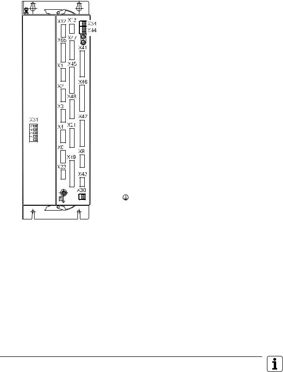
3.7.1 LE 370 D
X1 to
X4 Position encoder
X6 Encoder for spindle position
X8 Nominal value output
X12 Triggering touch probe for workpiece measurement
X13 Triggering touch probe for tool measurement
X21 RS-232-C/V24 data interface
X23 Handwheel input
X30 Reference signal for spindle
X41 PLC output
X42 PLC input
X44 PLC power supply
X43 Flat-panel display BF 370 B
X45 TNC keyboard
X46 Machine operating panel
X47 PLC expansion PL410B/PL405B
X48 PLC analog input
X31 NC power supply
B Signal ground
Protective ground (YL/GN)
3–10 |
TNC 370 D |
Mounting and Electrical Installation |
July 02 |
3.7.2 Power Supply
X31 NC Power Supply
Terminal |
Assignment |
|
X31 |
|
|
|
|
|
PE |
Protective ground (YL/GN) |
|
|
|
|
U1 |
L1 |
330 Vac to 450 Vac; |
U2 |
L2 |
50 to 60 Hz |
–UZ |
Do not use |
|
+UZ |
Do not use |
|
Danger to internal components!
Do not engage or disengage any connections while the unit is under power.
July 02 |
Mounting and Electrical Installation |
TNC 370 D 3–11 |

X44 PLC Power Supply
Terminal |
Assignment |
Fuse |
|
|
|
|
|
1 |
+ 24 |
Vdc can be switched off via EMERGENCY STOP |
F 3,15 A |
|
|
|
|
2 |
+ 24 |
Vdc cannot be switched off via EMERGENCY STOP |
F 2 A |
|
|
|
|
3 |
0 V |
|
|
|
|
|
|
HEIDENHAIN recommends that you operate the PLC of the LE (and the PL 410B/PL 405B) with a 24 V control voltage that is generated as per VDE 0551. The control voltage must be smoothed with approx. 150µF / A (at 15 A, this corresponds to a smoothing capacity of 2250 µF), where a minimum capacity of 1000µF (63V) is to be ensured.
The 0 V line of the PLC power voltage must be connected by a grounding line ( 6 mm2) with the central signal ground of the machine.
Supply |
Voltage range, |
Max. current consumption |
Current |
|||
voltage |
mean dc voltage |
(when half of the outputs |
consumption |
|||
|
|
|
|
|
are on simultaneously) |
(when half of the |
|
|
|
|
|
|
outputs are on |
|
|
|
|
|
|
simultaneously) |
|
|
|
|
|||
24 Vdc |
Lower limit |
LE 370 D: 2 A |
LE 370 D: 48 W |
|||
|
19,2 V - - -, |
|
|
|
|
|
|
|
|
|
|||
EN 61 131- |
Upper limit |
|
|
|||
2: 1994; |
30 V - - -, |
|
|
|
|
|
|
|
|
||||
VDE 0411 Part |
|
|
|
|
|
|
500 |
|
|
|
|
|
|
|
|
|
|
|
|
|
Besides the voltage tolerance, a dc component with a peak value of 5% of the rated voltage is permissible. The absolute limits lie at 30 V/19.2 V.
Danger to internal components!
Use only original replacement fuses.
3–12 |
TNC 370 D |
Mounting and Electrical Installation |
July 02 |

3.7.3 Measuring System Inputs
HEIDENHAIN TNC contouring controls are designed for use with incremental linear and angular encoders as measuring systems.
However, HEIDENHAIN recommends using encoders with distance-coded reference marks because they significantly reduce the traverse distance required to establish the absolute position.
Maximum current load per encoder input: |
200 mA |
Use only original HEIDENHAIN encoder cables, connectors and couplings. For maximum cable lengths see “Cable Overview.”
Encoder for Position with 1 VSS
Maximum input frequency: 350 kHz (via MP 115.1 switchable to 50 kHz)
X1, X2, X3, X4 and X6 (Spindle) Encoder (1 VPP) (via MP 115.0 switchable to 11µA)
|
Logic unit |
|
D-sub |
|
Assignment |
|
||
terminal |
|
|
(male) 15-pin |
|
|
|
|
|
1 |
|
+ 5 V (UP) |
2 |
|
0 V (UN) |
3 |
|
A+ |
|
|
|
4 |
|
A– |
|
|
|
5 |
|
0 V |
|
|
|
6 |
|
B+ |
|
|
|
7 |
|
B– |
|
|
|
8 |
|
0 V |
|
|
|
9 |
|
+ 5 V |
|
|
|
10 |
|
R+ |
|
|
|
11 |
|
0 V |
|
|
|
12 |
|
R– |
|
|
|
13 |
|
0 V |
|
|
|
14 |
|
Do not use |
|
|
|
15 |
|
Do not use |
|
|
|
Housing |
|
External shield |
|
|
|
Encoder cable |
|
D-sub |
|
|
|
connector |
|
(female) 15-pin |
|
|
|
1 |
Brown/Green |
|
|
2 |
White/Green |
|
|
3 |
Brown |
|
|
4 |
Green |
|
|
5 |
|
|
|
6 |
Gray |
|
|
7 |
Pink |
|
|
8 |
|
|
|
9 |
Blue |
|
|
10 |
Red |
|
|
11 |
White |
|
|
12 |
Black |
|
|
13 |
|
|
|
14 |
Violet |
|
|
15 |
|
|
|
Housing |
External shield |
|
|
For the spindle position, HEIDENHAIN recommends the ROD 486 with 1024 or 2048 lines. The 1 VPP signals are interpolated by a factor of 1024.
July 02 |
Mounting and Electrical Installation |
TNC 370 D 3–13 |

3.7.4 Reference Signal for the Spindle
Usually, the reference mark of the spindle encoder is evaluated as a reference signal for the spindle. In special cases, a 24 V signal on terminal X30 can be evaluated as a reference signal for the spindle or as a reference signal release (see chapter “Spindle”). For reliable evaluation, the signal must last for at least 3 milliseconds.
X30 Spindle Reference Signal
Terminal |
Assignment |
|
|
1 |
+24 V input |
|
|
2 |
0 V |
|
|
3.7.5 Supply voltage for Control-is-Ready Signal
The power supply for the control-is-ready signal is taken from the 24 V power supply of the PLC.
X34 power supply for control-is-ready signal
Connecting terminal |
Assignment |
|
|
1 |
+24 V PLC |
|
|
2 |
0 V |
|
|
3–14 |
TNC 370 D |
Mounting and Electrical Installation |
July 02 |

3.7.6 Analog Nominal Value Output
Maximum loading of the analog outputs: |
2 mA |
Maximum capacitance: |
2 nF |
X8 Nominal Value Output
|
|
Logic unit |
|
D-sub terminal |
|
Assignment |
|
|
|||
(female) 15-pin |
|
|
|
|
|
|
|
1 |
|
Nominal value output 1 |
|
|
|
|
|
2 |
|
Analog input |
|
|
|
|
|
3 |
|
Nominal value output 2 |
|
|
|
|
|
4 |
|
Do not use |
|
|
|
|
|
5 |
|
Nominal value output 3 |
|
|
|
|
|
6 |
|
Do not use |
|
|
|
|
|
7 |
|
Nominal value output 4 |
|
|
|
|
|
8 |
|
Nominal value output 5 |
|
|
|
|
|
9 |
|
0V |
Nominal value output 1 |
|
|
|
|
10 |
|
0V |
Analog input |
|
|
|
|
11 |
|
0V |
Nominal value output 2 |
|
|
|
|
12 |
|
Do not use |
|
|
|
|
|
13 |
|
0V |
Nominal value output 3 |
|
|
|
|
14 |
|
0V |
Nominal value output 4 |
|
|
|
|
15 |
|
0V |
Nominal value output 5 |
|
|
|
|
Housing |
|
External shield |
|
|
|
|
|
Connecting Cable |
||
D-sub |
|
Color |
|
||
connector |
|
|
(male) 15-pin |
|
|
|
|
|
1 |
|
BN |
|
|
|
2 |
|
BN/GN |
|
|
|
3 |
|
YL |
|
|
|
4 |
|
RD/BL |
|
|
|
5 |
|
PK |
|
|
|
6 |
|
GY/PK |
|
|
|
7 |
|
RD |
|
|
|
8 |
|
VI |
|
|
|
9 |
|
WH |
|
|
|
10 |
|
WH/GY |
|
|
|
11 |
|
GN |
|
|
|
12 |
|
|
|
|
|
13 |
|
GY |
|
|
|
14 |
|
BL |
|
|
|
15 |
|
BK |
|
|
|
Housing |
|
External shield |
|
|
|
The connecting cables to the nominal value outputs must not have more than one intermediate terminal.
If it is necessary to branch to physically separate servo inputs, the connection must be made in a grounded terminal box. Suitable terminal boxes are available from HEIDENHAIN (Id. Nr. 251 249 01).
The chassis of the terminal box must be electrically connected with frame of the machine.
The 0 V connection of the nominal-value-difference inputs must be connected with signal ground. Required cross section Ø 6 mm².
Use only original HEIDENHAIN connecting cables and connecting elements.
July 02 |
Mounting and Electrical Installation |
TNC 370 D 3–15 |
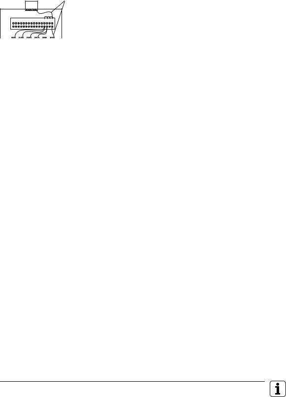
The following wiring plan is suggested for shielding in the terminal box :
LE
•
1 |
2 |
3 |
4 |
5 |
6 |
7 |
8 |
9 10 11 12 13 14 15 16 |
•
|
|
|
|
|
|
|
|
|
|
|
|
|
|
|
X |
|
Y |
|
Z |
|
IV |
|
|
|
S |
|
|
|
|
|
|
|
|
|
|
|
|
|
|
|
|
|
|
|
|
|
SERVO |
|
|
|
|
|
|||
Insulated against housing
Insulated against housing
Leads are provided with en sleeves.
Cable screens are led onto 0.14 mm2
insulated strands via crimp eyelets.
Leads are provided with end sleeves
Cable shields are led onto 0.14 mm² insulated wires via crimp eyelets.
Connection |
Assignment |
|
terminal |
|
|
|
|
|
1 |
Nominal value output |
X axis |
|
|
|
2 |
Nominal value output 0 V |
X axis |
|
|
|
3 |
Nominal value output |
Y axis |
|
|
|
4 |
Nominal value output 0 V |
Y axis |
|
|
|
5 |
Nominal value output |
Z axis |
|
|
|
6 |
Nominal value output 0 V |
Z axis |
|
|
|
7 |
Nominal value output |
IV axis |
|
|
|
8 |
Nominal value output 0 V |
IV axis |
|
|
|
9 |
Not used |
|
|
|
|
10 |
Not used |
|
|
|
|
11 |
Nominal value output |
S axis |
|
|
|
12 |
Nominal value output 0 V |
S axis |
|
|
|
13 |
Shield connection |
|
|
|
|
14 |
Shield connection |
|
|
|
|
15 |
Shield connection |
|
|
|
|
16 |
Shield connection |
|
|
|
|
3–16 |
TNC 370 D |
Mounting and Electrical Installation |
July 02 |

3.7.7 Switching Inputs 24 Vdc for the PLC
Voltage ranges: |
Logic unit |
|
PL 410 B/PL 405 B |
|
|
|
|
“1” signal: Ui |
|
13 V to 30.2 V |
|
|
|
|
|
“0” signal: Ui |
|
–20 V to 3.2 V |
|
|
|
|
|
Current ranges: |
|
|
|
|
|
|
|
“1” signal: Ii |
3.8 mA to 8.9 mA |
2.5 mA to 6 mA |
|
|
|
|
|
“0” signal: Ii when Ui = 3.2 V |
1.0 mA |
0.65 mA |
|
|
|
|
|
Address |
No. of inputs |
Device |
|
|
|
|
|
I0 to I31 |
31 + control-is-ready signal |
Logic unit X42 |
(PLC input) |
|
|
|
|
I128 to I152 |
25 |
Logic unit X46 |
(machine operating panel) |
|
|
|
|
I64 to I127 |
64 |
First PLC input/output board PL 410 B |
|
|
|
|
|
I92 to I255 |
64 |
Second PLC input/output board PL 410 B |
|
|
|
|
|
I64 to I95 |
32 |
PL 405 B |
|
|
|
|
|
July 02 |
Mounting and Electrical Installation |
TNC 370 D 3–17 |
X42 PLC Input at the LE
Logic unit |
|
|
D-sub connector |
|
Assignment |
|
||
(female) 37-pin |
|
|
1 |
|
D-sub connection (female) 37-pin |
|
|
|
2 |
|
I1 |
|
|
|
3 |
|
I2 |
|
|
|
4 |
|
I3 acknowledge "control-is-ready"; main processor |
|
|
|
5 |
|
I4 |
|
|
|
6 |
|
I5 |
|
|
|
7 |
|
I6 |
|
|
|
8 |
|
I7 |
|
|
|
9 |
|
I8 |
|
|
|
10 |
|
I9 |
|
|
|
11 |
|
I10 |
|
|
|
12 |
|
I11 |
|
|
|
13 |
|
I12 |
|
|
|
14 |
|
I13 |
|
|
|
15 |
|
I14 |
|
|
|
16 |
|
I15 |
|
|
|
17 |
|
I16 |
|
|
|
18 |
|
I17 |
|
|
|
19 |
|
I18 |
|
|
|
20 |
|
I19 |
|
|
|
21 |
|
I20 |
|
|
|
22 |
|
I21 |
|
|
|
23 |
|
I22 |
|
|
|
24 |
|
I23 |
|
|
|
25 |
|
I24 |
|
|
|
26 |
|
I25 |
|
|
|
27 |
|
I26 |
|
|
|
28 |
|
I27 |
|
|
|
29 |
|
I28 |
|
|
|
30 |
|
I29 |
|
|
|
31 |
|
I30 |
|
|
|
32 |
|
I31 |
|
|
|
33 |
|
I32 (do not use) |
|
|
|
34 |
|
Do not use |
|
|
|
35 |
|
0 V (PLC) Test output; Do not use |
|
|
|
36 |
|
0 V (PLC) Test output; Do not use |
|
|
|
37 |
|
0 V (PLC) Test output; Do not use |
|
|
|
Housing |
|
External shield |
|
|
|
Con. cable Id.-Nr 244 005 .. / Id. Nr. 263 954 ..
D-sub connector |
|
(male) 37-pin |
|
1 |
Gray/Red |
|
|
2 |
Brown/Black |
|
|
3 |
White/Black |
|
|
4 |
Green/Black |
|
|
5 |
Brown/Red |
|
|
6 |
White/Red |
|
|
7 |
White/Green |
|
|
8 |
Red/Blue |
|
|
9 |
Yellow/Red |
|
|
10 |
Gray/Pink |
|
|
11 |
Black |
|
|
12 |
Pink/Brown |
|
|
13 |
Yellow/Blue |
|
|
14 |
Green/Blue |
|
|
15 |
Yellow |
|
|
16 |
Red |
|
|
17 |
Gray |
|
|
18 |
Blue |
|
|
19 |
Pink |
|
|
20 |
White/Gray |
|
|
21 |
Yellow/Gray |
|
|
22 |
Green/Red |
|
|
23 |
White/Pink |
|
|
24 |
Gray/Green |
|
|
25 |
Yellow/Brown |
|
|
26 |
Gray/Brown |
|
|
27 |
Yellow/Black |
|
|
28 |
White/Yellow |
|
|
29 |
Gray/Blue |
|
|
30 |
Pink/Blue |
|
|
31 |
Pink/Red |
|
|
32 |
Brown/Blue |
|
|
33 |
Pink/Green |
|
|
34 |
Brown |
|
|
35 |
Yellow/Pink |
|
|
36 |
Violet |
|
|
37 |
White |
|
|
Housing |
External shield |
|
|
3–18 |
TNC 370 D |
Mounting and Electrical Installation |
July 02 |

PLC Input at the PL 410 B/PL 405 B
X3
Connection terminal |
Assignment |
||
|
1st PL 410 B |
|
2nd PL 410 B |
|
|
||
|
PL 405 B |
|
|
|
|
|
|
1 |
I64 |
|
I192 |
|
|
|
|
2 |
I65 |
|
I193 |
|
|
|
|
3 |
I66 |
|
I194 |
|
|
|
|
4 |
I67 |
|
I195 |
|
|
|
|
5 |
I68 |
|
I196 |
|
|
|
|
6 |
I69 |
|
I197 |
|
|
|
|
7 |
I70 |
|
I198 |
|
|
|
|
8 |
I71 |
|
I199 |
|
|
|
|
9 |
I72 |
|
I200 |
|
|
|
|
10 |
I73 |
|
I201 |
|
|
|
|
11 |
I74 |
|
I202 |
|
|
|
|
12 |
I75 |
|
I203 |
|
|
|
|
13 |
I76 |
|
I204 |
|
|
|
|
14 |
I77 |
|
I205 |
|
|
|
|
15 |
I78 |
|
I206 |
|
|
|
|
16 |
I79 |
|
I207 |
|
|
|
|
X5 |
|
|
|
|
|
||
Connection terminal |
Assignment |
||
|
1st PL 410 B |
|
2nd PL 410 B |
|
|
||
|
|
|
|
1 |
I96 |
|
I224 |
|
|
|
|
2 |
I97 |
|
I225 |
|
|
|
|
3 |
I98 |
|
I226 |
|
|
|
|
4 |
I99 |
|
I227 |
|
|
|
|
5 |
I100 |
|
I228 |
|
|
|
|
6 |
I101 |
|
I229 |
|
|
|
|
7 |
I102 |
|
I230 |
|
|
|
|
8 |
I103 |
|
I231 |
|
|
|
|
9 |
I104 |
|
I232 |
|
|
|
|
10 |
I105 |
|
I233 |
|
|
|
|
11 |
I106 |
|
I234 |
|
|
|
|
12 |
I107 |
|
I235 |
|
|
|
|
13 |
I108 |
|
I236 |
|
|
|
|
14 |
I109 |
|
I237 |
|
|
|
|
15 |
I110 |
|
I238 |
|
|
|
|
16 |
I111 |
|
I239 |
|
|
|
|
X4
Connection terminal |
Assignment |
||
|
1st PL 410 B |
|
2nd PL 410 B |
|
|
||
|
PL 405 B |
|
|
|
|
|
|
1 |
I80 |
|
I208 |
|
|
|
|
2 |
I81 |
|
I209 |
|
|
|
|
3 |
I82 |
|
I210 |
|
|
|
|
4 |
I83 |
|
I211 |
|
|
|
|
5 |
I84 |
|
I212 |
|
|
|
|
6 |
I85 |
|
I213 |
|
|
|
|
7 |
I86 |
|
I214 |
|
|
|
|
8 |
I87 |
|
I215 |
|
|
|
|
9 |
I88 |
|
I216 |
|
|
|
|
10 |
I89 |
|
I217 |
|
|
|
|
11 |
I90 |
|
I218 |
|
|
|
|
12 |
I91 |
|
I219 |
|
|
|
|
13 |
I92 |
|
I220 |
|
|
|
|
14 |
I93 |
|
I221 |
|
|
|
|
15 |
I94 |
|
I222 |
|
|
|
|
16 |
I95 |
|
I223 |
|
|
|
|
X6 |
|
|
|
|
|
||
Connection terminal |
Assignment |
||
|
1st PL 410 B |
|
2nd PL 410 B |
|
|
||
|
|
|
|
1 |
I112 |
|
I240 |
|
|
|
|
2 |
I113 |
|
I241 |
|
|
|
|
3 |
I114 |
|
I242 |
|
|
|
|
4 |
I115 |
|
I243 |
|
|
|
|
5 |
I116 |
|
I244 |
|
|
|
|
6 |
I117 |
|
I245 |
|
|
|
|
7 |
I118 |
|
I246 |
|
|
|
|
8 |
I119 |
|
I247 |
|
|
|
|
9 |
I120 |
|
I248 |
|
|
|
|
10 |
I121 |
|
I249 |
|
|
|
|
11 |
I122 |
|
I250 |
|
|
|
|
12 |
I123 |
|
I251 |
|
|
|
|
13 |
I124 |
|
I252 |
|
|
|
|
14 |
I125 |
|
I253 |
|
|
|
|
15 |
I126 |
|
I254 |
|
|
|
|
16 |
I127 |
|
I255 |
|
|
|
|
July 02 |
Mounting and Electrical Installation |
TNC 370 D 3–19 |

3.7.8 Switching Outputs 24 Vdc for the PLC
Transistor outputs with current limiting
|
Logic unit |
PL 410 B/PL 405 B |
|
|
|
Min. output voltage for “1” signal |
3 V below supply voltage |
|
|
|
|
Nominal operating current per output |
0.125 A with simultaneity |
1.2 A with simultaneity |
|
factor of 0.5 |
factor of 0.5; |
|
|
2 A with max. current |
|
|
consumption of 20 A |
|
|
|
Permissible load: resistive load; inductive load only with quenching diode parallel to the inductance.
No more than one output may be shorted on the logic unit at any time. Short circuit of one output does not cause an overload.
No more than half the PLC outputs may be driven at the same time (simultaneity factor 0.5).
Address |
No. of outputs |
Device |
|
|
|
O0 to O30 |
31 |
Logic unit X41 (PLC output) |
|
|
|
O0 to O7 |
|
Logic unit X46 (machine operating panel) |
|
|
|
O32 to O62 |
31 |
First PL 410 B |
|
|
|
O64 to O94 |
31 |
Second PL 410 B |
|
|
|
O48 to O62 |
15 |
PL 405 B |
|
|
|
X44 Power Supply for the outputs of the LE
Terminal |
Assignment |
PLC outputs |
|
|
|
|
|
|
|
1 |
+24 |
Vdc can be switched off via EMERGENCY |
O0 to O23 |
|
|
STOP |
|
|
|
|
|
|
|
|
2 |
+24 |
Vdc cannot be switched off via EMERGENCY |
O24 to O30 |
|
|
STOP |
|
|
|
|
|
|
|
|
3 |
0V |
|
|
|
|
|
|
|
|
Power Supply for the outputs on the PL 410 B/ PL 405 B |
|
|
||
|
|
|
|
|
Terminal |
Assignment |
1st PL 410 B |
2nd PL 410 B |
|
|
|
|
Pl 405 B |
|
|
|
|
|
|
X9 |
0 V |
|
|
|
|
|
|
|
|
X10 |
+24 |
Vdc power supply for logic and for control-is-ready signal |
|
|
|
|
|
|
|
X11 |
+24 |
Vdc power supply for outputs |
O32 to O39 |
O64 to O71 |
|
|
|
|
|
X12 |
+24 |
Vdc power supply for outputs |
O40 to O47 |
O72 to O79 |
|
|
|
|
|
X13 |
+24 |
Vdc power supply for outputs |
O48 to O55 |
O80 to O87 |
|
|
|
|
|
X14 |
+24 |
Vdc power supply for outputs |
O56 to O62 |
O88 to O94 |
|
|
|
|
|
For connecting the PL 410 B to the LE, see section 3.9.14.
3–20 |
TNC 370 D |
Mounting and Electrical Installation |
July 02 |

X41 PLC Outputs on the LE
|
|
Logic unit |
D-sub terminal |
|
Assignment |
|
||
(female) 37-pin |
|
|
1 |
|
O0 |
2 |
|
O1 |
|
|
|
3 |
|
O2 |
|
|
|
4 |
|
O3 |
|
|
|
5 |
|
O4 |
6 |
|
O5 |
|
|
|
7 |
|
O6 |
|
|
|
8 |
|
O7 |
|
|
|
9 |
|
O8 |
10 |
|
O9 |
|
|
|
11 |
|
O10 |
|
|
|
12 |
|
O11 |
|
|
|
13 |
|
O12 |
14 |
|
O13 |
|
|
|
15 |
|
O14 |
|
|
|
16 |
|
O15 |
|
|
|
17 |
|
O16 |
18 |
|
O17 |
19 |
|
O18 |
|
|
|
20 |
|
O19 |
|
|
|
21 |
|
O20 |
|
|
|
22 |
|
O21 |
23 |
|
O22 |
|
|
|
24 |
|
O23 |
|
|
|
25 |
|
O24 |
|
|
|
26 |
|
O25 |
27 |
|
O26 |
|
|
|
28 |
|
O27 |
|
|
|
29 |
|
O28 |
|
|
|
30 |
|
O29 |
31 |
|
O30 |
|
|
|
32 |
|
Do not use |
|
|
|
33 |
|
Do not use |
|
|
|
34 |
|
Control-is-ready signal |
35 |
|
24 V (PLC) test output; Do not use |
|
|
|
36 |
|
24 V (PLC) test output; Do not use |
|
|
|
37 |
|
24 V (PLC) test output; Do not use |
|
|
|
Housing |
|
External shield |
Connecting cable
Id. Nr 244 005 .. / Id. Nr. 263 954 ..
D-sub connector |
|
(male) 37-pin |
|
1 |
Gray/Red |
2 |
Brown/Black |
|
|
3 |
White/Black |
|
|
4 |
Green/Black |
|
|
5 |
Brown/Red |
6 |
White/Red |
|
|
7 |
White/Green |
|
|
8 |
Red/Blue |
|
|
9 |
Yellow/Red |
10 |
Gray/Pink |
|
|
11 |
Black |
|
|
12 |
Pink/Brown |
|
|
13 |
Yellow/Blue |
14 |
Green/Blue |
|
|
15 |
Yellow |
|
|
16 |
Red |
|
|
17 |
Gray |
18 |
Blue |
19 |
Pink |
|
|
20 |
White/Gray |
|
|
21 |
Yellow/Gray |
|
|
22 |
Green/Red |
23 |
White/Pink |
|
|
24 |
Gray/Green |
|
|
25 |
Yellow/Brown |
|
|
26 |
Gray/Brown |
27 |
Yellow/Black |
|
|
28 |
White/Yellow |
|
|
29 |
Gray/Blue |
|
|
30 |
Pink/Blue |
31 |
Pink/Red |
|
|
32 |
Brown/Blue |
|
|
33 |
Pink/Green |
|
|
34 |
Brown |
35 |
Yellow/Pink |
|
|
36 |
Violet |
|
|
37 |
White |
|
|
Housing |
External shield |
July 02 |
Mounting and Electrical Installation |
TNC 370 D 3–21 |

PLC Outputs on the PL 410 B/PL405 B
X7
Connection terminal |
Assignment |
||
|
1st PL 410 B |
|
2nd PL 410 B |
|
|
||
|
|
|
|
1 |
O32 |
|
O64 |
|
|
|
|
2 |
O33 |
|
O65 |
|
|
|
|
3 |
O34 |
|
O66 |
|
|
|
|
4 |
O35 |
|
O67 |
|
|
|
|
5 |
O36 |
|
O68 |
|
|
|
|
6 |
O37 |
|
O69 |
|
|
|
|
7 |
O38 |
|
O70 |
|
|
|
|
8 |
O39 |
|
O71 |
|
|
|
|
9 |
O40 |
|
O72 |
|
|
|
|
10 |
O41 |
|
O73 |
|
|
|
|
11 |
O42 |
|
O74 |
|
|
|
|
12 |
O43 |
|
O75 |
|
|
|
|
13 |
O44 |
|
O76 |
|
|
|
|
14 |
O45 |
|
O77 |
|
|
|
|
15 |
O46 |
|
O78 |
|
|
|
|
16 |
O47 |
|
O79 |
|
|
|
|
X8
Connection terminal |
Assignment |
||
|
1st PL 410 B |
|
2nd PL 410 B |
|
|
||
|
PL 405 B |
|
|
|
|
|
|
1 |
O48 |
|
O80 |
|
|
|
|
2 |
O49 |
|
O81 |
|
|
|
|
3 |
O50 |
|
O82 |
|
|
|
|
4 |
O51 |
|
O83 |
|
|
|
|
5 |
O52 |
|
O84 |
|
|
|
|
6 |
O53 |
|
O85 |
|
|
|
|
7 |
O54 |
|
O86 |
|
|
|
|
8 |
O55 |
|
O87 |
|
|
|
|
9 |
O56 |
|
O88 |
|
|
|
|
10 |
O57 |
|
O89 |
|
|
|
|
11 |
O58 |
|
O90 |
|
|
|
|
12 |
O59 |
|
O91 |
|
|
|
|
13 |
O60 |
|
O92 |
|
|
|
|
14 |
O61 |
|
O93 |
|
|
|
|
15 |
O62 |
|
O94 |
|
|
|
|
16 |
Control-is-ready signal |
||
|
|
|
|
3–22 |
TNC 370 D |
Mounting and Electrical Installation |
July 02 |

3.7.9 Machine Operating Panel
Logic unit |
|
Connecting cable Id. Nr. 263 954 .. |
|
|
TE 370 |
|||||
D-sub terminal |
|
Assignment |
|
D-sub |
|
D-sub connector |
|
X3 D-sub |
|
Key |
|
|
|
|
|
||||||
(female) 37-pin |
|
|
|
connector |
|
(female) 37-pin |
|
connector |
|
|
|
|
|
|
(male) 37-pin |
|
|
|
(female) 37-pin |
|
|
|
|
|
|
|
|
|
|
|
|
|
1 |
|
I128 |
|
1 |
Gray/Red |
1 |
|
1 |
|
Coolant ON |
|
|
|
|
|
|
|
|
|
|
|
2 |
|
I129 |
|
2 |
Brown/Black |
2 |
|
2 |
|
Coolant OFF |
|
|
|
|
|
|
|
|
|
|
|
3 |
|
I130 |
|
3 |
White/Black |
3 |
|
3 |
|
Spindle OFF |
|
|
|
|
|
|
|
|
|
|
|
4 |
|
I131 |
|
4 |
Green/Black |
4 |
|
4 |
|
NC STOP |
|
|
|
|
|
|
|
|
|
|
|
5 |
|
I132 |
|
5 |
Brown/Red |
5 |
|
5 |
|
NC START |
|
|
|
|
|
|
|
|
|
|
|
6 |
|
I133 |
|
6 |
White/Red |
6 |
|
6 |
|
X- |
|
|
|
|
|
|
|
|
|
|
|
7 |
|
I134 |
|
7 |
White/Green |
7 |
|
7 |
|
Y- |
|
|
|
|
|
|
|
|
|
|
|
8 |
|
I135 |
|
8 |
Red/Blue |
8 |
|
8 |
|
Z- |
|
|
|
|
|
|
|
|
|
|
|
9 |
|
I136 |
|
9 |
Yellow/Red |
9 |
|
9 |
|
Z+ |
|
|
|
|
|
|
|
|
|
|
|
10 |
|
I137 |
|
10 |
Gray/Pink |
10 |
|
10 |
|
Y+ |
|
|
|
|
|
|
|
|
|
|
|
11 |
|
I138 |
|
11 |
Black |
11 |
|
11 |
|
X+ |
|
|
|
|
|
|
|
|
|
|
|
12 |
|
I139 |
|
12 |
Pink/Brown |
12 |
|
12 |
|
4+ |
|
|
|
|
|
|
|
|
|
|
|
13 |
|
I140 |
|
13 |
Yellow/Blue |
13 |
|
13 |
|
4- |
|
|
|
|
|
|
|
|
|
|
|
14 |
|
I141 |
|
14 |
Green/Blue |
14 |
|
14 |
|
Rapid traverse |
|
|
|
|
|
|
|
|
|
|
|
15 |
|
I142 |
|
15 |
Yellow |
15 |
|
15 |
|
Spindle ON |
|
|
|
|
|
|
|
|
|
|
|
16 |
|
I143 |
|
16 |
Red |
16 |
|
16 |
|
- |
|
|
|
|
|
|
|
|
|
|
|
17 |
|
I144 |
|
17 |
Gray |
17 |
|
17 |
|
- |
|
|
|
|
|
|
|
|
|
|
|
18 |
|
I145 |
|
18 |
Blue |
18 |
|
18 |
|
- |
|
|
|
|
|
|
|
|
|
|
|
19 |
|
I146 |
|
19 |
Pink |
19 |
|
19 |
|
- |
|
|
|
|
|
|
|
|
|
|
|
20 |
|
I147 |
|
20 |
White/Gray |
20 |
|
20 |
|
KEY F5 |
|
|
|
|
|
|
|
|
|
|
|
21 |
|
I148 |
|
21 |
Yellow/Gray |
21 |
|
21 |
|
KEY F1 |
|
|
|
|
|
|
|
|
|
|
|
22 |
|
I149 |
|
22 |
Green/Red |
22 |
|
22 |
|
KEY F2 |
|
|
|
|
|
|
|
|
|
|
|
23 |
|
I150 |
|
23 |
White/Pink |
23 |
|
23 |
|
KEY F3 |
|
|
|
|
|
|
|
|
|
|
|
24 |
|
I151 |
|
24 |
Gray/Green |
24 |
|
24 |
|
KEY F4 |
|
|
|
|
|
|
|
|
|
|
|
25 |
|
I152 |
|
25 |
Yellow/Brown |
25 |
|
25 |
|
- |
|
|
|
|
|
|
|
|
|
|
|
26 |
|
O0 |
|
26 |
Gray/Brown |
26 |
|
26 |
|
|
|
|
|
|
|
|
|
|
|
|
|
27 |
|
O1 |
|
27 |
Yellow/Black |
27 |
|
27 |
|
|
|
|
|
|
|
|
|
|
|
|
|
28 |
|
O2 |
|
28 |
White/Yellow |
28 |
|
28 |
|
|
|
|
|
|
|
|
|
|
|
|
|
29 |
|
O3 |
|
29 |
Gray/Blue |
29 |
|
29 |
|
|
|
|
|
|
|
|
|
|
|
|
|
30 |
|
O4 |
|
30 |
Pink/Blue |
30 |
|
30 |
|
|
|
|
|
|
|
|
|
|
|
|
|
31 |
|
O5 |
|
31 |
Pink/Red |
31 |
|
31 |
|
|
|
|
|
|
|
|
|
|
|
|
|
32 |
|
O6 |
|
32 |
Brown/Blue |
32 |
|
32 |
|
|
|
|
|
|
|
|
|
|
|
|
|
33 |
|
O7 |
|
33 |
Pink/Green |
33 |
|
33 |
|
|
|
|
|
|
|
|
|
|
|
|
|
34 |
|
0 V (PLC) |
|
34 |
Brown |
34 |
|
34 |
|
|
|
|
|
|
|
|
|
|
|
|
|
35 |
|
0 V (PLC) |
|
35 |
Yellow/Pink |
35 |
|
35 |
|
|
|
|
|
|
|
|
|
|
|
|
|
36 |
|
+24 V (PLC) |
|
36 |
Violet |
36 |
|
36 |
|
|
|
|
|
|
|
|
|
|
|
|
|
37 |
|
+24 V (PLC) |
|
37 |
White |
37 |
|
37 |
|
|
|
|
|
|
|
|
|
|
|
|
|
Housing |
|
External |
|
Housing |
External shield |
Housing |
|
Housing |
|
|
|
|
shield |
|
|
|
|
|
|
|
|
|
|
|
|
|
|
|
|
|
|
|
July 02 |
Mounting and Electrical Installation |
TNC 370 D 3–23 |

3.7.10 TNC Keyboard
The TNC keyboard is connected by cable with the logic unit, and by flat cable with the soft keys of the visual display unit. The flat cable is included with the visual display unit.
X1 on the TNC Keyboard for Connecting the Soft Keys of the Visual Display Unit
Connecting element |
Assignment |
(male) 9-pin |
|
|
|
1 |
SL0 |
|
|
2 |
SL1 |
|
|
3 |
SL2 |
|
|
4 |
SL3 |
|
|
5 |
Do not use |
|
|
6 |
RL15 |
|
|
7 |
RL14 |
|
|
8 |
RL13 |
|
|
9 |
RL12 |
|
|
3–24 |
TNC 370 D |
Mounting and Electrical Installation |
July 02 |

X45 TNC Keyboard (TE 370)
|
|
Logic unit |
|
Connecting cable Id. Nr. 263 954 .. |
|
TE 420 |
||
D-sub terminal |
|
Assignment |
|
D-sub |
|
D-sub connector |
|
X2 D-sub terminal |
|
|
|
|
|||||
(female) 37-pin |
|
|
|
connector |
|
(female) 37-pin |
|
(male) 37-pin |
|
|
|
|
(male) 37-pin |
|
|
|
|
1 |
|
RL0 |
|
1 |
Gray/Red |
1 |
|
1 |
|
|
|
|
|
|
|
|
|
2 |
|
RL1 |
|
2 |
Brown/Black |
2 |
|
2 |
|
|
|
|
|
|
|
|
|
3 |
|
RL2 |
|
3 |
White/Black |
3 |
|
3 |
|
|
|
|
|
|
|
|
|
4 |
|
RL3 |
|
4 |
Green/Black |
4 |
|
4 |
|
|
|
|
|
|
|
|
|
5 |
|
RL4 |
|
5 |
Brown/Red |
5 |
|
5 |
|
|
|
|
|
|
|
|
|
6 |
|
RL5 |
|
6 |
White/Red |
6 |
|
6 |
|
|
|
|
|
|
|
|
|
7 |
|
RL6 |
|
7 |
White/Green |
7 |
|
7 |
|
|
|
|
|
|
|
|
|
8 |
|
RL7 |
|
8 |
Red/Blue |
8 |
|
8 |
|
|
|
|
|
|
|
|
|
9 |
|
RL8 |
|
9 |
Yellow/Red |
9 |
|
9 |
|
|
|
|
|
|
|
|
|
10 |
|
RL9 |
|
10 |
Gray/Pink |
10 |
|
10 |
|
|
|
|
|
|
|
|
|
11 |
|
RL10 |
|
11 |
Black |
11 |
|
11 |
|
|
|
|
|
|
|
|
|
12 |
|
RL11 |
|
12 |
Pink/Brown |
12 |
|
12 |
|
|
|
|
|
|
|
|
|
13 |
|
RL12 |
|
13 |
Yellow/Blue |
13 |
|
13 |
|
|
|
|
|
|
|
|
|
14 |
|
RL13 |
|
14 |
Green/Blue |
14 |
|
14 |
|
|
|
|
|
|
|
|
|
15 |
|
RL14 |
|
15 |
Yellow |
15 |
|
15 |
|
|
|
|
|
|
|
|
|
16 |
|
RL15 |
|
16 |
Red |
16 |
|
16 |
|
|
|
|
|
|
|
|
|
17 |
|
RL16 |
|
17 |
Gray |
17 |
|
17 |
|
|
|
|
|
|
|
|
|
18 |
|
RL17 |
|
18 |
Blue |
18 |
|
18 |
|
|
|
|
|
|
|
|
|
19 |
|
RL18 |
|
19 |
Pink |
19 |
|
19 |
|
|
|
|
|
|
|
|
|
20 |
|
SL0 |
|
20 |
White/Gray |
20 |
|
20 |
|
|
|
|
|
|
|
|
|
21 |
|
SL1 |
|
21 |
Yellow/Gray |
21 |
|
21 |
|
|
|
|
|
|
|
|
|
22 |
|
SL2 |
|
22 |
Green/Red |
22 |
|
22 |
|
|
|
|
|
|
|
|
|
23 |
|
SL3 |
|
23 |
White/Pink |
23 |
|
23 |
|
|
|
|
|
|
|
|
|
24 |
|
SL4 |
|
24 |
Gray/Green |
24 |
|
24 |
|
|
|
|
|
|
|
|
|
25 |
|
SL5 |
|
25 |
Yellow/Brown |
25 |
|
25 |
|
|
|
|
|
|
|
|
|
26 |
|
SL6 |
|
26 |
Gray/Brown |
26 |
|
26 |
|
|
|
|
|
|
|
|
|
27 |
|
SL7 |
|
27 |
Yellow/Black |
27 |
|
27 |
|
|
|
|
|
|
|
|
|
28 |
|
RL19 |
|
28 |
White/Yellow |
28 |
|
28 |
|
|
|
|
|
|
|
|
|
29 |
|
RL20 |
|
29 |
Gray/Blue |
29 |
|
29 |
|
|
|
|
|
|
|
|
|
30 |
|
Not used |
|
30 |
Pink/Blue |
30 |
|
30 |
|
|
|
|
|
|
|
|
|
31 |
|
RL21 |
|
31 |
Pink/Red |
31 |
|
31 |
|
|
|
|
|
|
|
|
|
32 |
|
RL22 |
|
32 |
Brown/Blue |
32 |
|
32 |
|
|
|
|
|
|
|
|
|
33 |
|
RL23 |
|
33 |
Pink/Green |
33 |
|
33 |
|
|
|
|
|
|
|
|
|
34 |
|
Spindle override (wiper) |
|
34 |
Brown |
34 |
|
34 |
|
|
|
|
|
|
|
|
|
35 |
|
Feed rate override (wiper) |
|
35 |
Yellow/Pink |
35 |
|
35 |
|
|
|
|
|
|
|
|
|
36 |
|
+5 V override potentiometer |
|
36 |
Violet |
36 |
|
36 |
|
|
|
|
|
|
|
|
|
37 |
|
0 V override potentiometer |
|
37 |
White |
37 |
|
37 |
|
|
|
|
|
|
|
|
|
July 02 |
Mounting and Electrical Installation |
TNC 370 D 3–25 |
 Loading...