


TNC 426
User's Manual
HEIDENHAIN
Conversational
Programming
7/99
TNC 426 B
TNC 430
NC Software
280 472 xx
280 473 xx
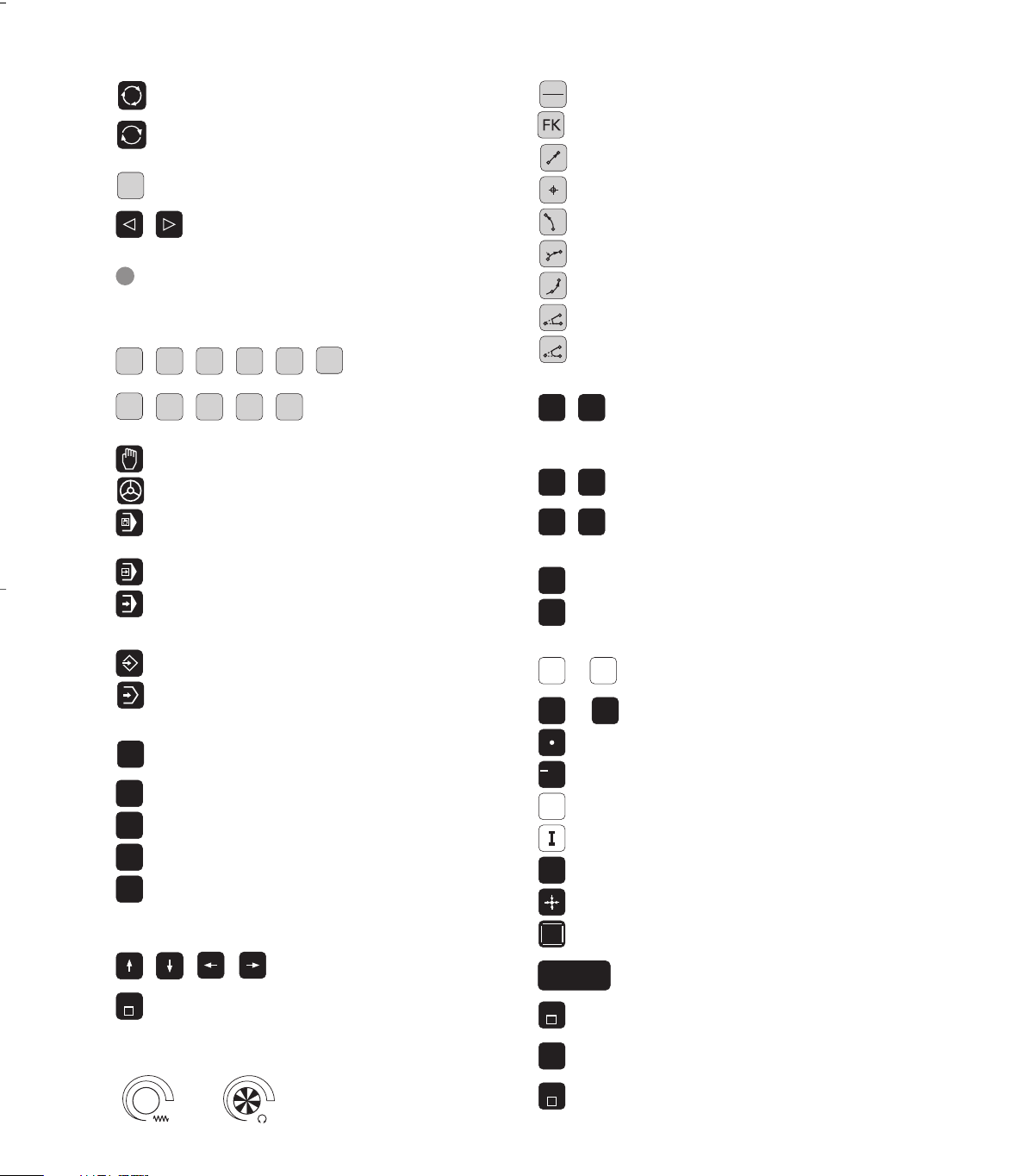
Controls on the visual display unit
Split screen layout
Switch between machining or
programming modes
Soft keys for selecting functions
in screen
Switching the soft-key rows
Changing the screen settings
(only BC 120)
Typewriter keyboard for entering letters and
symbols
Q
W E
R
T
Y
File name
Comments
G
F S T M
ISO programs
Machine operating modes
MANUAL OPERATION
ELECTRONIC HANDWHEEL Operating Modes
POSITIONING WITH MANUAL DATA INPUT
(MDI)
PROGRAM RUN, SINGLE BLOCK
PROGRAM RUN, FULL SEQUENCE
Programming modes
PROGRAMMING AND EDITING
TEST RUN
Program/file management, TNC functions
PGM
MGT
Select or delete programs and files
External data transfer
PGM
CALL
Enter program call in a program
MOD
MOD functions
HELP
Displaying help texts for NC error messages
CALC
Pocket calculator
Moving the cursor, going directly to blocks, cycles
and parameter functions
Move highlight
GOTO
Go directly to blocks, cycles and parameter
functions
Override control knobs for feed rate/spindle speed
Programming path movements
APPR
DEP
Approach/depart contour
FK free contour programming
L
Straight line
CC
Circle center/pole for polar coordinates
C
Circle with center
CR
Circle with radius
CT
Circular arc with tangential connection
CHF
Chamfer
RND
Corner rounding
Tool functions
TOOL
DEF
TOOL
CALL
Enter or call tool length and radius
Cycles, subprograms and program section
repeats
CYCL
DEF
CYCL
CALL
Define and call cycles
LBL
SET
LBL
CALL
Enter and call labels for
subprogramming and program
section repeats
STOP
Program stop in a program
TOUCH
PROBE
Enter touch probe functions in a program
Coordinate axes and numbers, editing
X
...
V
Select coordinate axes or enter
them in a program
0
...
9
Numbers
Decimal point
+
/
Change arithmetic sign
P
Polar coordinates
Incremental dimensions
Q
Q parameters
Capture actual position
NO
ENT
Skip dialog questions, delete words
ENT
Confirm entry and resume
dialog
END
End block
CE
Clear numerical entry or TNC error
message
DEL
Abort dialog, delete program section
Controls on the TNC
1
50
0
50
100
S %
1
50
0
50
100
F %


Contents
IHEIDENHAIN TNC 426 B, TNC 430
TNC Models, Software and
Features
This manual describes functions and features provided by
the TNCs as of the following NC software numbers.
TNC Model NC Software No.
TNC 426 CB, TNC 426 PB 280 472 xx
TNC 426 CF, TNC 426 PF 280 473 xx
TNC 430 CA, TNC 430 PA 280 472 xx
TNC 430 CE, TNC 430 PE 280 473 xx
The suffixes E and F indicate the export versions of the TNC
which have the following limitations:
■ Linear movement is possible in no more than 4 axes
simultaneously
The machine tool builder adapts the useable features of the
TNC to his machine by setting machine parameters. Some
of the functions described in this manual may not be
among the features provided by your machine tool.
TNC functions that may not be available on your machine
include:
■ Probing function for the 3-D touch probe
■ Digitizing option
■ Tool measurement with the TT 120
■ Rigid tapping
■ Returning to the contour after an interruption
Please contact your machine tool builder to become familiar
with the individual implementation of the control on your
machine.
Many machine manufacturers, as well as HEIDENHAIN,
offer programming courses for the TNCs. We recommend
these courses as an effective way of improving your
programming skill and sharing information and ideas with
other TNC users.
User's Manual - Touch Probe Cycles
All of the touch probe functions are described in a separate
manual. Please contact HEIDENHAIN if you require a copy
of this User's Manual. Id. Nr.: 329 203 xx.
Location of use
The TNC complies with the limits for a Class A device in
accordance with the specifications in EN 55022, and is
intended for use primarily in industrially-zoned areas.


Contents
IIIHEIDENHAIN TNC 426 B, TNC 430
Introduction
Manual Operation and Setup
Programming: Tools
Contents
Programming: Fundamentals of NC,
File Management, Programming Aids
Positioning with Manual Data Input (MDI)
Programming: Programming Contours
Programming: Miscellaneous Functions
Programming: Cycles
Programming: Subprograms and
Program Section Repeats
Programming: Q Parameters
Test Run and Program Run
MOD Functions
Tables and Overviews
1
2
3
4
5
6
7
8
9
10
11
12
13

Contents
Contents
IV
1 INTRODUCTION ..... 1
1.1 The TNC 426 B, the TNC 430 ..... 2
1.2 Visual Display Unit and Keyboard ..... 3
1.3 Modes of Operation ..... 5
1.4 Status Displays ..... 7
1.5 Accessories: HEIDENHAIN 3-D Touch Probes and Electronic Handwheels ..... 11
2 MANUAL OPERATION AND SETUP ..... 13
2.1 Switch-on, Switch-off ..... 14
2.2 Moving the Machine Axes ..... 15
2.3 Spindle Speed S, Feed Rate F and Miscellaneous Functions M ..... 17
2.4 Datum Setting (Without a 3-D Touch Probe) ..... 18
2.5 Tilting the Working Plane ..... 19
3 POSITIONING WITH MANUAL DATA INPUT (MDI) ..... 23
3.1 Programming and Executing Simple Machining Operations ..... 24
4 PROGRAMMING: FUNDAMENTALS OF NC, FILE MANAGEMENT,
PROGRAMMING AIDS, PALLET MANAGEMENT ..... 27
4.1 Fundamentals of NC ..... 28
4.2 File Management: Fundamentals ..... 33
4.3 Standard File Management ..... 34
4.4 File Management with Additional Functions ..... 40
4.5 Creating and Writing Programs ..... 53
4.6 Interactive Programming Graphics ..... 57
4.7 Structuring Programs ..... 58
4.8 Adding Comments ..... 59
4.9 Creating Text Files ..... 60
4.10 Integrated Pocket Calculator ..... 63
4.11 HELP for NC error messages ..... 64
4.12 Managing Pallet Tables ..... 65

Contents
VHEIDENHAIN TNC 426 B, TNC 430
5 PROGRAMMING: TOOLS ..... 67
5.1 Entering Tool-Related Data ..... 68
5.2 Tool Data ..... 69
5.3 Tool Compensation ..... 78
5.4 Three-Dimensional Tool Compensation ..... 82
5.5 Working with Cutting Data Tables ..... 84
6 PROGRAMMING: PROGRAMMING CONTOURS ..... 91
6.1 Overview of Tool Movements ..... 92
6.2 Fundamentals of Path Functions ..... 93
6.3 Contour Approach and Departure ..... 96
Overview: Types of paths for contour approach and departure ..... 96
Important positions for approach and departure ..... 96
Approaching on a straight line with tangential connection: APPR LT ..... 97
Approaching on a straight line perpendicular to the first contour point: APPR LN ..... 98
Approaching on a circular arc with tangential connection: APPR CT ..... 98
Approaching on a circular arc with tangential connection from a straight line to the contour:
APPR LCT ..... 99
Departing tangentially on a straight line: DEP LT ..... 100
Departing on a straight line perpendicular to the last contour point: DEP LN ..... 100
Departing tangentially on a circular arc: DEP CT ..... 101
Departing on a circular arc tangentially connecting the contour and a straight line: DEP LCT ..... 101
6.4 Path Contours — Cartesian Coordinates ..... 102
Overview of path functions ..... 102
Straight line L ..... 103
Inserting a chamfer CHF between two straight lines ..... 103
Circle center CC ..... 104
Circular path C around circle center CC ..... 105
Circular path CR with defined radius ..... 106
Circular path CT with tangential connection ..... 107
Corner Rounding RND ..... 108
Example: Linear movements and chamfers with Cartesian coordinates ..... 109
Example: Circular movements with Cartesian coordinates ..... 110
Example: Full circle with Cartesian coordinates ..... 111

Contents
Contents
VI
6.5 Path Contours—Polar Coordinates ..... 112
Polar coordinate origin: Pole CC ..... 112
Straight line LP ..... 113
Circular path CP around pole CC ..... 113
Circular path CTP with tangential connection ..... 114
Helical interpolation ..... 114
Example: Linear movement with polar coordinates ..... 116
Example: Helix ..... 117
6.6 Path Contours — FK Free Contour Programming ..... 118
Fundamentals ..... 118
Graphics during FK programming ..... 118
Initiating the FK dialog ..... 119
Free programming of straight lines ..... 120
Free programming of circular arcs ..... 120
Auxiliary points ..... 122
Relative data ..... 123
Closed contours ..... 125
Converting FK programs ..... 125
Example: FK programming 1 ..... 126
Example: FK programming 2 ..... 127
Example: FK programming 3 ..... 128
6.7 Path Contours - Spline Interpolation ..... 130

Contents
VIIHEIDENHAIN TNC 426 B, TNC 430
7 PROGRAMMING: MISCELLANEOUS FUNCTIONS ..... 133
7.1 Entering Miscellaneous Functions M and STOP ..... 134
7.2 Miscellaneous Functions for Program Run Control, Spindle and Coolant ..... 135
7.3 Miscellaneous Functions for Coordinate Data ..... 135
7.4 Miscellaneous Functions for Contouring Behavior ..... 138
Smoothing corners: M90 ..... 138
Insert rounding arc between straight lines: M112 ..... 139
Machining small contour steps: M97 ..... 139
Machining open contours: M98 ..... 140
Feed rate factor for plunging movements: M103 ..... 141
Feed rate at circular arcs: M109/M110/M111 ..... 142
Calculating the radius-compensated path in advance (LOOK AHEAD): M120 ..... 142
Superimposing handwheel positioning during program run: M118 ..... 143
7.5 Miscellaneous Functions for Rotary Axes ..... 144
Feed rate in mm/min on rotary axes A, B, C: M116 ..... 144
Shorter-path traverse of rotary axes: M126 ..... 144
Reducing display of a rotary axis to a value less than 360°: M94 ..... 145
Automatic compensation of machine geometry when working with tilted axes: M114 ..... 146
Maintaining the position of the tool tip when positioning with tilted axes (TCPM*): M128 ..... 147
Exact stop at corners with nontangential transitions: M134 ..... 148
7.6 Miscellaneous Functions for Laser Cutting Machines ..... 149

Contents
Contents
VIII
PROGRAMMING: CYCLES ..... 151
8.1 General Information on Cycles ..... 152
8.2 Drilling Cycles ..... 154
PECKING (Cycle 1) ..... 154
DRILLING (Cycle 200) ..... 156
REAMING (Cycle 201) ..... 157
BORING (Cycle 202) ..... 158
UNIVERSAL DRILLING (Cycle 203) ..... 159
BACK BORING (Cycle 204) ..... 161
TAPPING with a floating tap holder (Cycle 2) ..... 163
RIGID TAPPING (Cycle 17) ..... 164
THREAD CUTTING (Cycle 18) ..... 165
Example: Drilling cycles ..... 166
Example: Drilling cycles ..... 167
8.3 Cycles for milling pockets, studs and slots ..... 168
POCKET MILLING (Cycle 4) ..... 169
POCKET FINISHING (Cycle 212) ..... 170
STUD FINISHING (Cycle 213) ..... 172
CIRCULAR POCKET MILLING (Cycle 5) ..... 173
CIRCULAR POCKET FINISHING (Cycle 214) ..... 175
CIRCULAR STUD FINISHING (Cycle 215) ..... 176
SLOT MILLING (Cycle 3) ..... 178
SLOT with reciprocating plunge-cut (Cycle 210) ..... 179
CIRCULAR SLOT with reciprocating plunge-cut (Cycle 211) ..... 181
Example: Milling pockets, studs and slots ..... 183
8.4 Cycles for Machining Hole Patterns ..... 185
CIRCULAR PATTERN (Cycle 220) ..... 186
LINEAR PATTERN (Cycle 221) ..... 187
Example: Circular hole patterns ..... 189

Contents
IXHEIDENHAIN TNC 426 B, TNC 430
8.5 SL Cycles ..... 191
CONTOUR GEOMETRY (Cycle 14) ..... 193
Overlapping contours ..... 193
CONTOUR DATA (Cycle 20) ..... 195
PILOT DRILLING (Cycle 21) ..... 197
ROUGH-OUT (Cycle 22) ..... 198
FLOOR FINISHING (Cycle 23) ..... 199
SIDE FINISHING (Cycle 24) ..... 199
CONTOUR TRAIN (Cycle 25) ..... 200
CYLINDER SURFACE (Cycle 27) ..... 202
Example: Roughing-out and fine-roughing a pocket ..... 205
Example: Pilot drilling, roughing-out and finishing overlapping contours ..... 206
Example: Contour train ..... 208
Example: Cylinder surface ..... 210
8.6 Cycles for Multipass Milling ..... 212
RUN DIGITIZED DATA (Cycle 30) ..... 212
MULTIPASS MILLING (Cycle 230) ..... 214
RULED SURFACE (Cycle 231) ..... 216
Example: Multipass milling ..... 219
8.7 Coordinate Transformation Cycles ..... 219
DATUM SHIFT (Cycle 7) ..... 220
DATUM SHIFT with datum tables (Cycle 7) ..... 221
MIRROR IMAGE (Cycle 8) ..... 224
ROTATION (Cycle 10) ..... 225
SCALING FACTOR (Cycle 11) ..... 226
AXIS-SPECIFIC SCALING (Cycle 26) ..... 227
WORKING PLANE (Cycle 19) ..... 228
Example: Coordinate transformation cycles ..... 233
8.8 Special Cycles ..... 235
DWELL TIME (Cycle 9) ..... 235
PROGRAM CALL (Cycle 12) ..... 235
ORIENTED SPINDLE STOP (Cycle 13) ..... 236
TOLERANCE (Cycle 32) ..... 237

Contents
Contents
X
9 PROGRAMMING: SUBPROGRAMS AND PROGRAM SECTION REPEATS ..... 239
9.1 Marking Subprograms and Program Section Repeats ..... 240
9.2 Subprograms ..... 240
9.3 Program Section Repeats ..... 241
9.4 Program as Subprogram ..... 242
9.5 Nesting ..... 243
Subprogram within a subprogram ..... 243
Repeating program section repeats ..... 244
Repeating a subprogram ..... 245
9.6 Programming Examples ..... 246
Example: Milling a contour in several infeeds ..... 246
Example: Groups of holes ..... 247
Example: Groups of holes with several tools ..... 248
10 PROGRAMMING: Q PARAMETERS ..... 251
10.1 Principle and Overview ..... 252
10.2 Part Families — Q Parameters in Place of Numerical Values ..... 254
10.3 Describing Contours Through Mathematical Functions ..... 255
10.4 Trigonometric Functions ..... 257
10.5 Calculating Circles ..... 258
10.6 If-Then Decisions with Q Parameters ..... 259
10.7 Checking and Changing Q Parameters ..... 260
10.8 Additional Functions ..... 261
10.9 Entering Formulas Directly ..... 270
10.10 Preassigned Q Parameters ..... 273
10.11 Programming Examples ..... 276
Example: Ellipse ..... 276
Example: Concave cylinder machined with spherical cutter ..... 278
Example: Convex sphere machined with end mill ..... 280
11 TEST RUN AND PROGRAM RUN ..... 283
11.1 Graphics ..... 284
11.2 Functions for Program Display in Program Run and Test Run ..... 289
11.3 Test run ..... 289
11.4 Program Run ..... 291
11.5 Optional block skip ..... 296

Contents
XIHEIDENHAIN TNC 426 B, TNC 430
12 MOD FUNCTIONS ..... 297
12.1 Selecting, Changing and Exiting the MOD Functions ..... 298
12.2 Software Numbers and Option Numbers ..... 299
12.3 Code Number ..... 299
12.4 Setting the Data Interfaces ..... 300
12.5 Ethernet Interface ..... 304
12.6 Configuring PGM MGT ..... 311
12.7 Machine-Specific User Parameters ..... 311
12.8 Showing the Workpiece in the Working Space ..... 311
12.9 Position Display Types ..... 313
12.10Unit of Measurement ..... 313
12.11 Programming Language for $MDI ..... 314
12.12 Selecting the Axes for Generating L Blocks ..... 314
12.13 Axis Traverse Limits, Datum Display ..... 314
12.14 Displaying HELP files ..... 315
12.15 Machining Times ..... 316
13 TABLES AND OVERVIEWS ..... 317
13.1 General User Parameters ..... 318
13.2 Pin Layout and Connecting Cable for the Data Interfaces ..... 333
13.3 Technical Information ..... 337
13.4 Exchanging the Buffer Battery ..... 340

Introduction
1
2
1.1 The TNC 426 B, the TNC 430
HEIDENHAIN TNC controls are workshop-oriented contouring
controls that enable you to program conventional machining
operations right at the machine in an easy-to-use conversational
programming language. They are designed for milling, drilling and
boring machines, as well as for machining centers. The TNC 426 B
can control up to 5 axes; the TNC 430 can control up to 9 axes. You
can also change the angular position of the spindle under program
control.
An integrated hard disk provides storage for as many programs as
you like, even if they were created off-line or by digitizing. For quick
calculations you can call up the on-screen pocket calculator at any
time.
Keyboard and screen layout are clearly arranged in a such way that
the functions are fast and easy to use.
Programming: HEIDENHAIN conversational and ISO formats
HEIDENHAIN conversational programming is an especially easy
method of writing programs. Interactive graphics illustrate the
individual machining steps for programming the contour. If a
production drawing is not dimensioned for NC, the HEIDENHAIN
FK free contour programming carries out the necessary calculations
automatically. Workpiece machining can be graphically simulated
either during or before actual machining. It is also possible to
program in ISO format or DNC mode.
You can also enter and test one program while the TNC is running
another.
Compatibility
The TNC can execute all part programs that were written on
HEIDENHAIN controls TNC 150 B and later.
The TNC 426 B, the TNC 430
1 Introduction
3HEIDENHAIN TNC 426 B, TNC 430
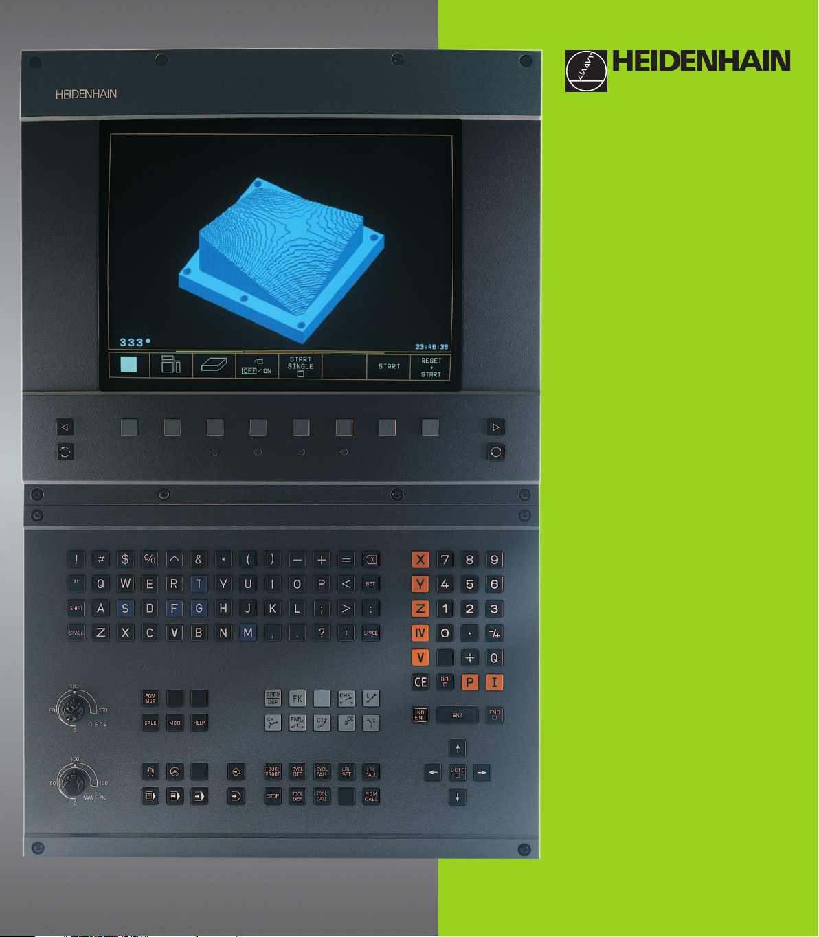
1.2 Visual Display Unit and Keyboard
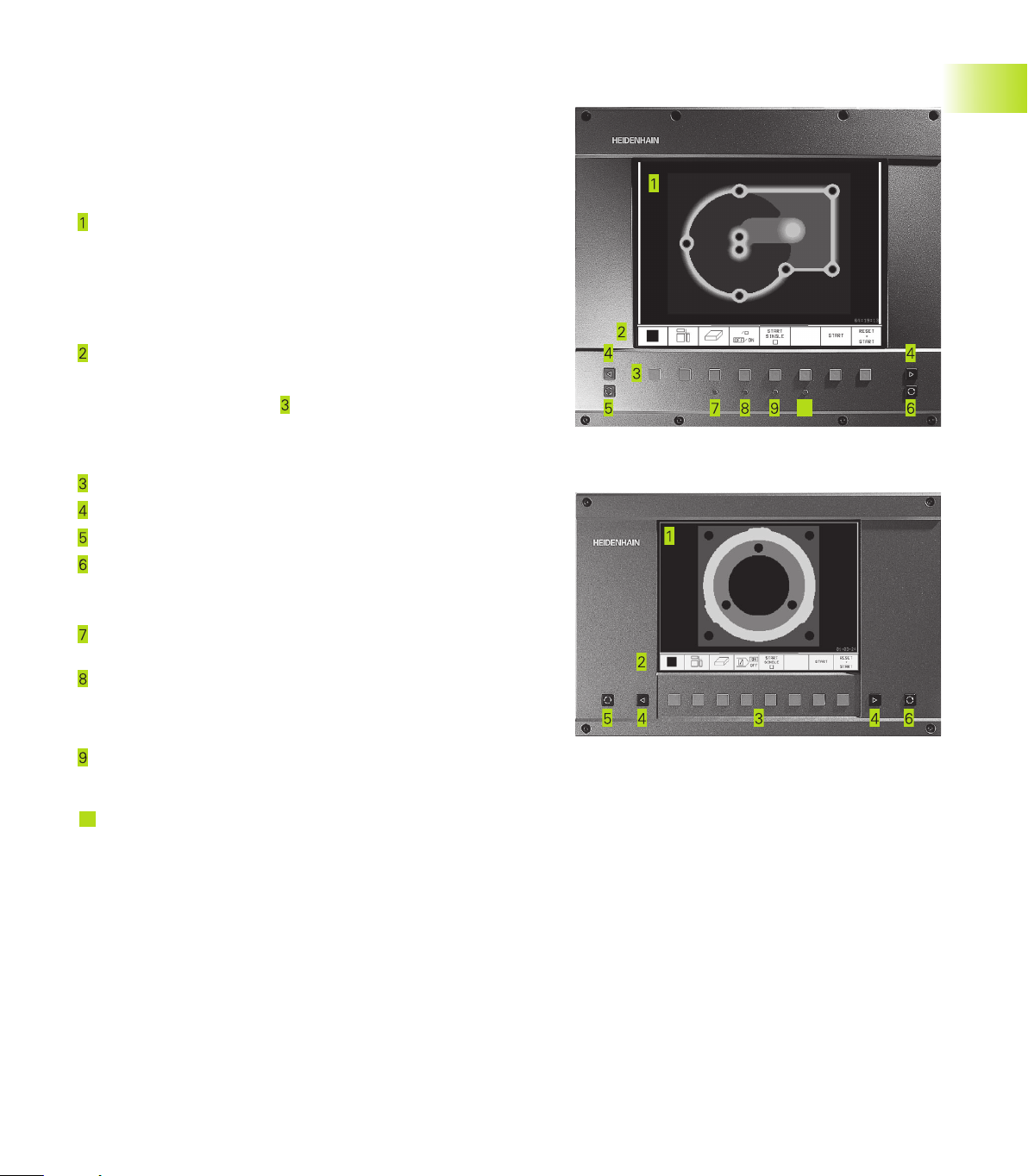
Visual display unit
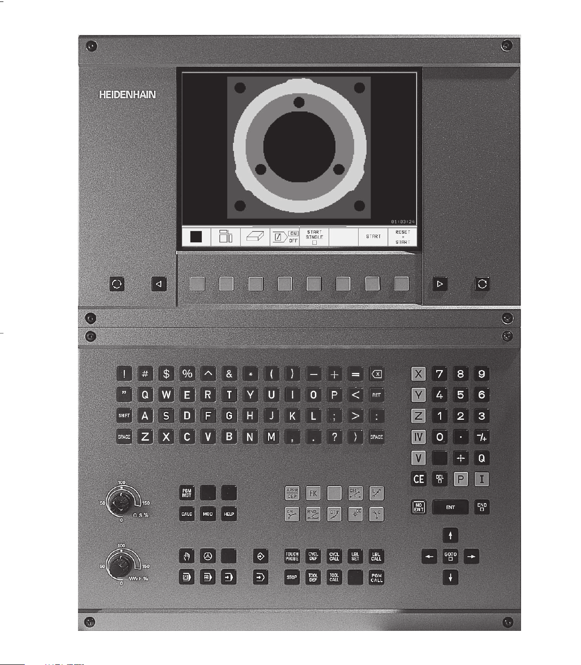
The TNC is available with either a color CRT screen (BC 120) or a
TFT flat panel display (BF 120. The figures at right show the keys
and controls on the BC 120 (upper right) and the BF 120 (middle
right).
Header
When the TNC is on, the selected operating modes are shown
in the screen header: the machining mode at the left and the
programming mode at right. The currently active mode is
displayed in the larger box, where the dialog prompts and TNC
messages also appear (unless the TNC is showing only
graphics).
Soft keys
In the footer the TNC indicates additional functions in a soft-key
row. You can select these functions by pressing the keys
immediately below them
. The lines immediately above the
soft-key row indicate the number of soft-key rows that can be
called with the black arrow keys to the right and left. The line
representing the active soft-key row is highlighted.
Soft key selector keys
Switching the soft-key rows
Setting the screen layout
Shift key for switchover between machining and programming
modes
Keys on BC 120 only
Screen demagnetization;
Exit main menu for screen settings
Select main menu for screen settings;
In the main menu: Move highlight downward
In the submenu: Reduce value
Move picture to the left or downward
In the main menu: Move highlight upward
In the submenu: Increase value
Move picture to the right or upward
10
In the main menu: Select submenu
In the submenu: Exit submenu
See next page for the screen settings.
10
1.2 Visual Display Unit and Keyboard
4
1.2 Visual Display Unit and Keyboard
1 Introduction
Main menu dialog Function
BRIGHTNESS Adjust brightness
CONTRAST Adjust contrast
H-POSITION Adjust horizontal position
H-SIZE Adjust picture width
V-POSITION Adjust vertical position
V-SIZE Adjust picture height
SIDE-PIN Correct barrel-shaped distortion
TRAPEZOID Correct trapezoidal distortion
ROTATION Correct tilting
COLOR TEMP Adjust color temperature
R-GAIN Adjust strength of red color
B-GAIN Adjust strength of blue color
RECALL No function
The BC 120 is sensitive to magnetic and electromagnetic noise,
which can distort the position and geometry of the picture.
Alternating fields can cause the picture to shift periodically or to
become distorted.
Screen layout
You select the screen layout yourself: In the PROGRAMMING AND
EDITING mode of operation, for example, you can have the TNC
show program blocks in the left window while the right window
displays programming graphics. You could also display the program
structure in the right window instead, or display only program
blocks in one large window. The available screen windows depend
on the selected operating mode.
To change the screen layout:
Press the switch-over key: The soft-key row
shows the available layout options (see section
1.3 ”Modes of Operation”).
<
Select the desired screen layout.
5HEIDENHAIN TNC 426 B, TNC 430
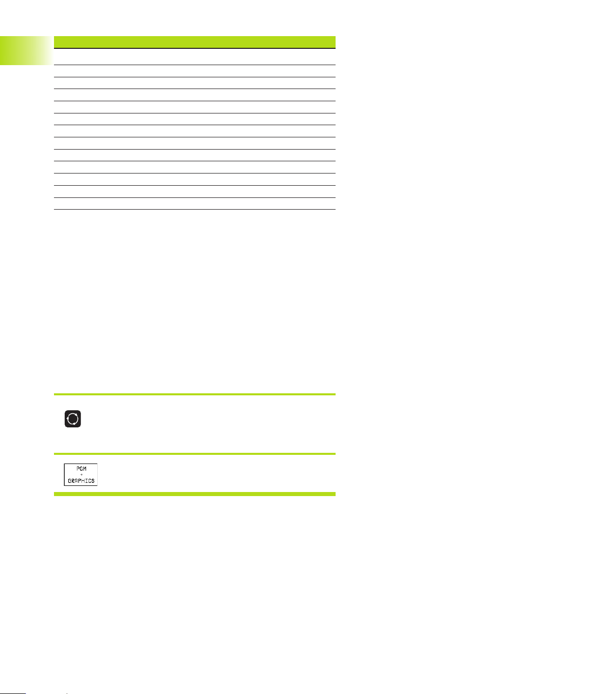
Keyboard
The figure at right shows the keys of the keyboard grouped
according to their functions:
Alphanumeric keyboard
for entering texts and file names, as well as for programming in
ISO format
File management,
pocket calculator,
MOD functions,
HELP functions
Programming modes
Machine operating modes
Initiation of programming dialog
Arrow keys and GOTO jump command
Numerical input and axis selection
The functions of the individual keys are described on the inside
front cover. Machine panel buttons, e.g. NC START, are described in
the manual for your machine tool.
1.3 Modes of Operation
The TNC offers the following modes of operation for the various
functions and working steps that you need to machine a workpiece:
Manual Operation and Electronic Handwheel
The Manual Operation mode is required for setting up the machine
tool. In this operating mode, you can position the machine axes
manually or by increments, set the datums, and tilt the working
plane.
The Electronic Handwheel mode of operation allows you to move
the machine axes manually with the HR electronic handwheel.
Soft keys for selecting the screen layout
(select as described previously)
Screen windows Soft key
Positions
Left: positions. Right: status display.
1.3 Modes of Operation
6
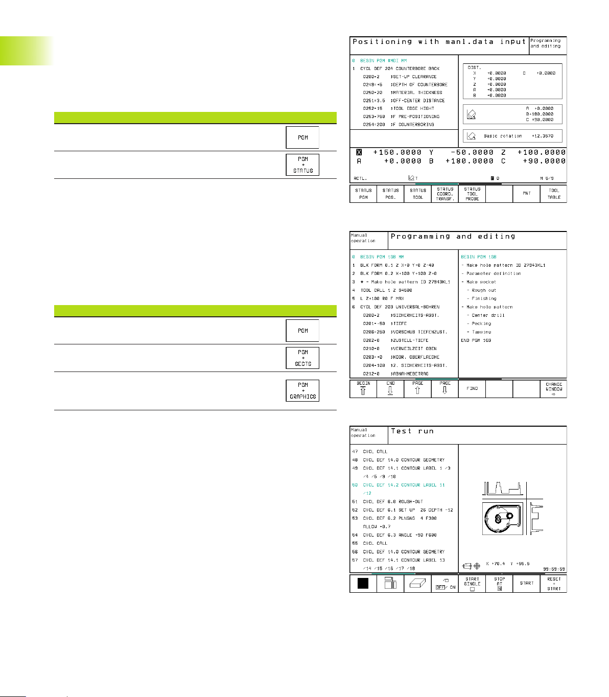
Positioning with Manual Data Input (MDI)
This mode of operation is used for programming simple traversing
movements, such as for face milling or pre-positioning. You can also
define point tables for setting the digitizing range in this mode.
Soft keys for selecting the screen layout
Screen windows Soft key
Program
Left: program blocks, right: status display
Programming and Editing
In this mode of operation you can write your part programs. The FK
free programming feature, the various cycles and the Q parameter
functions help you with programming and add necessary
information. If desired, you can have the programming graphics
show the individual steps, or you can use a separate screen
window to prepare your program structure.
Soft keys for selecting the screen layout
Screen windows Soft key
Program
Left: program blocks, right: program structure
Left: program blocks, right: programming
graphics
Test run
In the Test Run mode of operation, the TNC checks programs and
program sections for errors, such as geometrical incompatibilities,
missing or incorrect data within the program or violations of the
work space. This simulation is supported graphically in different
display modes.
Soft keys for selecting the screen layout
Same as in the Program Run operating modes on the next page.
1.3 Modes of Operation
1 Introduction
7HEIDENHAIN TNC 426 B, TNC 430
1.4 Status Displays1.4 Status Displays
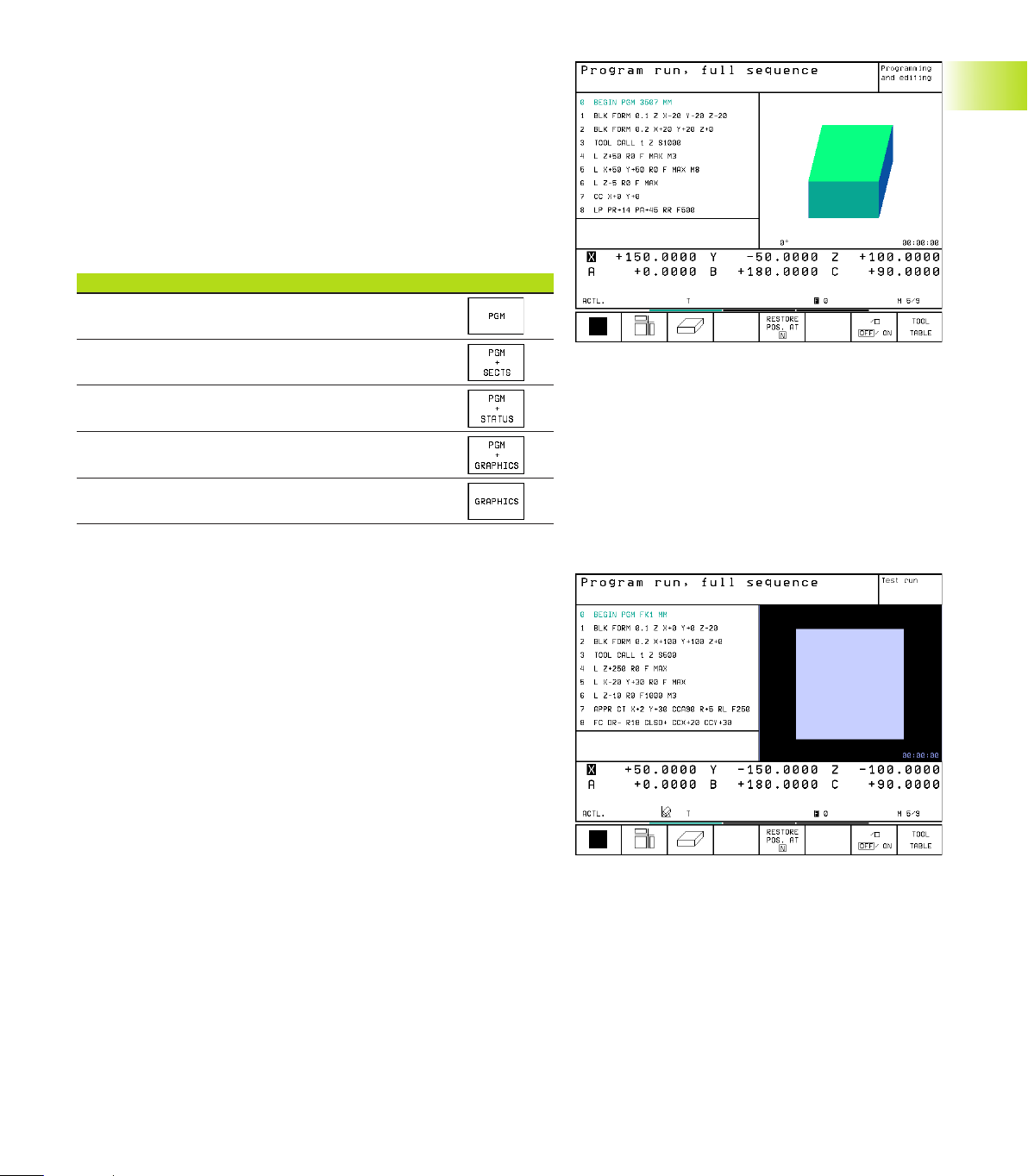
Program Run, Full Sequence and
Program Run, Single Block
In the Program Run, Full Sequence mode of operation the TNC
executes a part program continuously to its end or to a manual or
programmed stop. You can resume program run after an
interruption.
In the Program Run, Single Block mode of operation you execute
each block separately by pressing the machine START button.
Soft keys for selecting the screen layout
Screen windows Soft key
Program
Left: program blocks, right: program structure
Left: program blocks, right: STATUS
Left: program blocks, right: graphics
Graphics
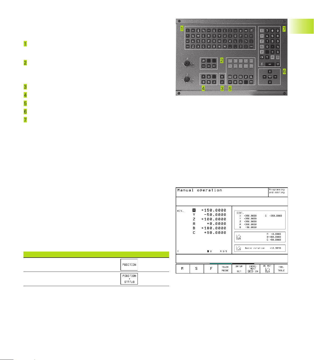
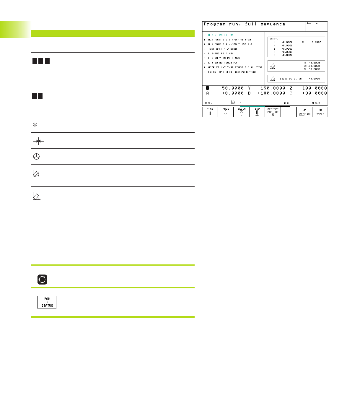
1.4 Status Displays
“General” status display
The status display informs you of the current state of the machine
tool. It is displayed automatically in the following modes of
operation:
■ Program Run, Single Block and Program Run, Full Sequence,
except if the screen layout is set to display graphics only, and
■ Positioning with Manual Data Input (MDI).
In the operating modes Manual and Electronic Handwheel, the
status display is shown in the large window.
8
1 Introduction
Information in the status display
The Meaning
ACTL. Actual or nominal coordinates of the current position
X Y Z Machine axes; the TNC displays auxiliary axes in
lower-case letters. The sequence and quantity of
displayed axes is determined by the machine tool builder.
Refer to your machine manual for more information
F S M The displayed feed rate in inches corresponds to
one tenth of the effective value.
Spindle speed S, feed rate F and active M functions
Program run started
Axis locked
Axis can be moved with the handwheel
Axes are moving in a tilted working
plain
Axes are moving under a basic
rotation
Additional status displays
The additional status displays contain detailed information on the
program run. They can be called in all operating modes, except in
the Programming and Editing mode of operation.
To switch on the additional status display:
Call the soft-key row for screen layout.
<
Select the layout option for the additional status
display.
1.4 Status Displays

9HEIDENHAIN TNC 426 B, TNC 430
You can choose between several additional status displays with the
following soft keys:
Shift the soft-key rows until the STATUS soft
keys appear.
<
Select the desired additional status display,
e.g. general program information.
General program information
Name of main program
Active programs
Active machining cycle
Circle center CC (pole)
Operating time
Dwell time counter
Positions and coordinates
Position display
Type of position display, e.g. actual positions
Tilt angle of the working plane
Angle of a basic rotation
1.4 Status Displays
10
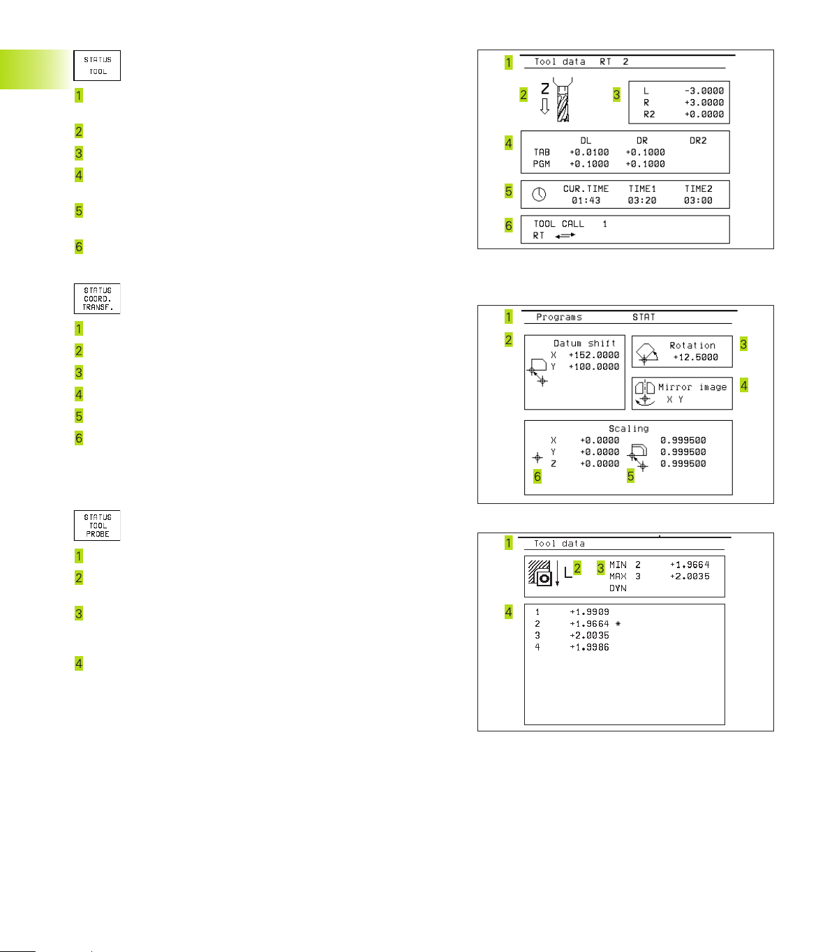
Information on tools
T: Tool number and name
RT: Number and name of a replacement tool
Tool axis
Tool length and radii
Oversizes (delta values) from TOOL CALL (PGM) and the tool
table (TAB)
Tool life, maximum tool life (TIME 1) and maximum tool life for
TOOL CALL (TIME 2)
Display of the active tool and the (next) replacement tool
Coordinate transformations
Name of main program
Active datum shift (Cycle 7)
Active rotation angle (Cycle 10)
Mirrored axes (Cycle 8)
Active scaling factor(s) (Cycles 11 / 26)
Scaling datum
See also section 8.7 “Coordinate Transformation Cycles.”
Tool measurement
Number of the tool to be measured
Display whether the tool radius or the tool length is being
measured
MIN and MAX values of the individual cutting edges and the
result of measuring the rotating tool (DYN = dynamic
measurement)
Cutting edge number with the corresponding measured value.
If the measured value is followed by an asterisk, the allowable
tolerance in the tool table was exceeded.
1 Introduction
1.4 Status Displays
11HEIDENHAIN TNC 426 B, TNC 430
1.5 Accessories: HEIDENHAIN 3-D
Touch Probes and Electronic
Handwheels
3-D Touch Probes
With the various HEIDENHAIN 3-D touch probe systems you can:
■ Automatically align workpieces
■ Quickly and precisely set datums
■ Measure the workpiece during program run
■ Digitize 3-D surfaces (option), and
■ Measure and inspect tools
All of the touch probe functions are described in a
separate manual. Please contact HEIDENHAIN if you
require a copy of this User's Manual. Id. Nr.: 329 203 xx.
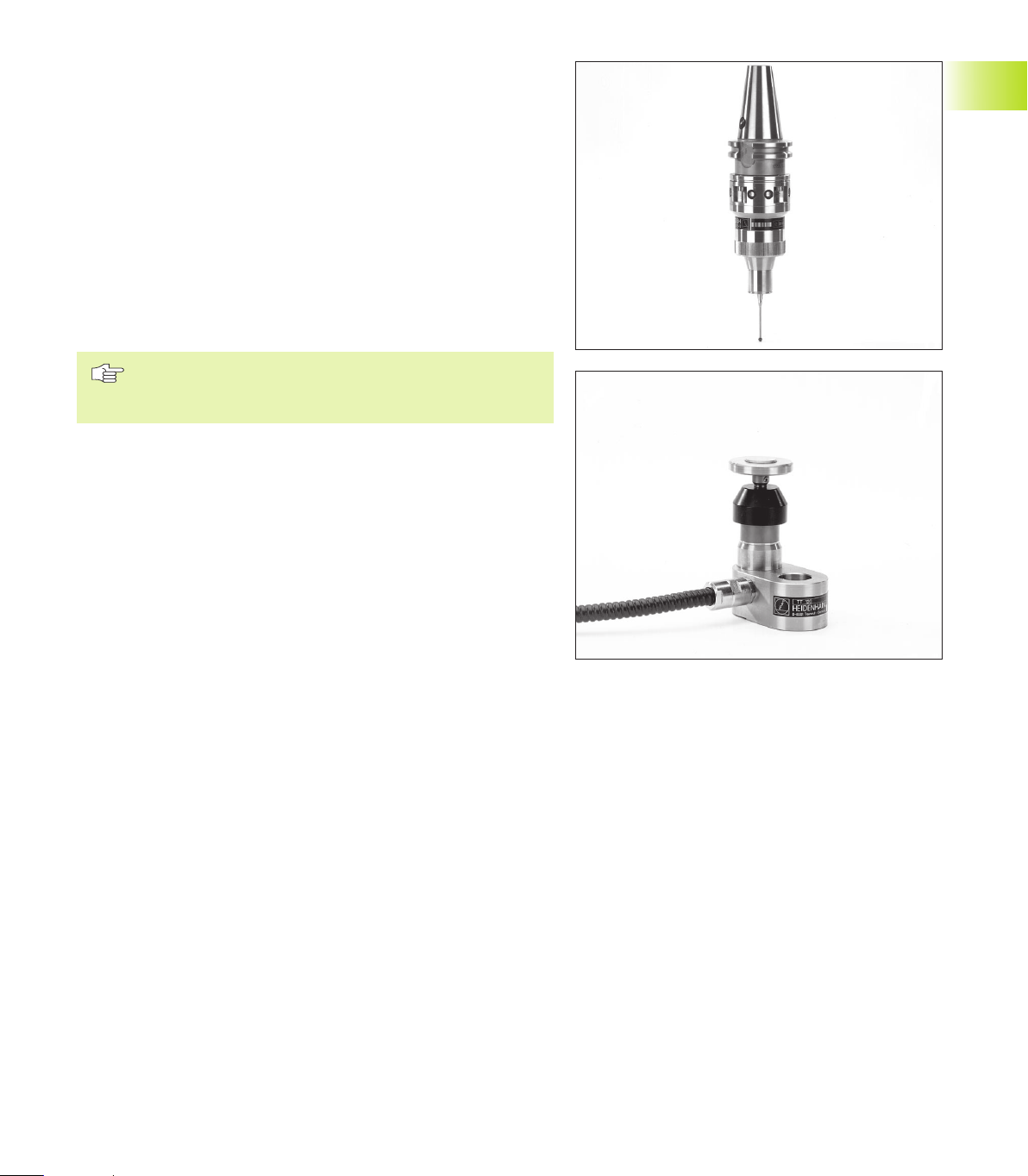
TS 220 and TS 630 touch trigger probes
These touch probes are particularly effective for automatic
workpiece alignment, datum setting, workpiece measurement and
for digitizing. The TS 220 transmits the triggering signals to the TNC
via cable and is a cost-effective alternative for applications where
digitizing is not frequently required.
The TS 630 features infrared transmission of the triggering signal to
the TNC. This makes it highly convenient for use on machines with
automatic tool changers.
Principle of operation: HEIDENHAIN triggering touch probes feature
a wear resisting optical switch that generates an electrical signal as
soon as the stylus is deflected. This signal is transmitted to the
TNC, which stores the current position of the stylus as an actual
value.
During digitizing the TNC generates a program containing straight
line blocks in HEIDENHAIN format from a series of measured
position data. You can then output the program to a PC for further
processing with the SUSA evaluation software. This evaluation
software enables you to calculate male/female transformations or
correct the program to account for special tool shapes and radii that
differ from the shape of the stylus tip. If the tool has the same
radius as the stylus tip you can run these programs immediately.
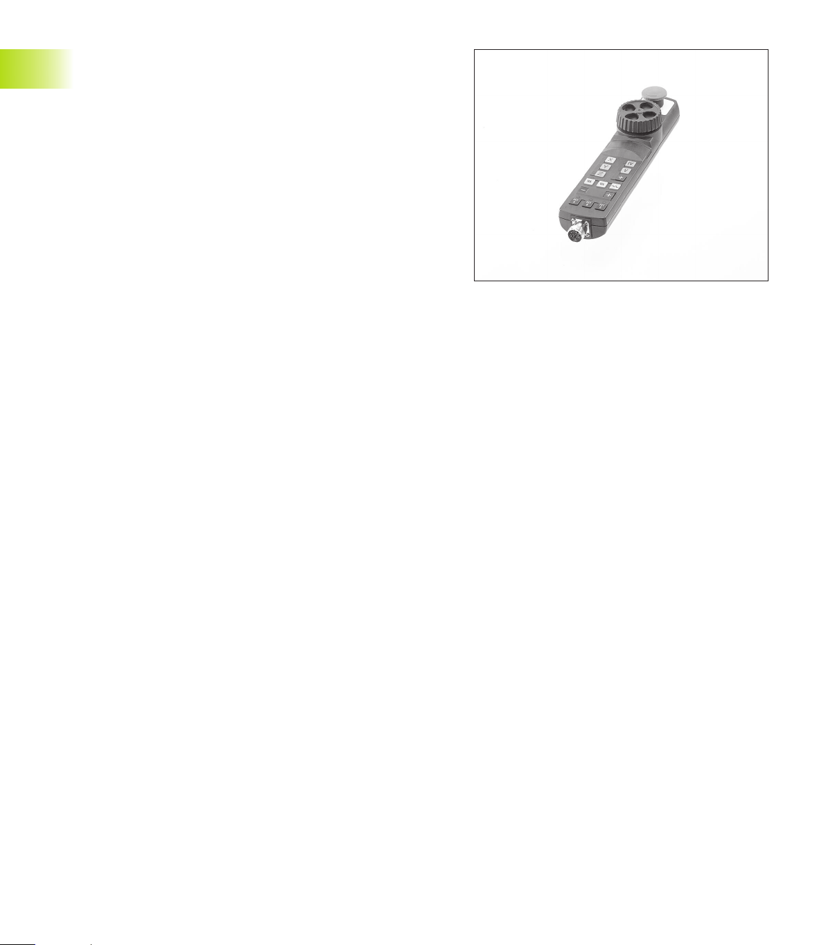
TT 120 tool touch probe for tool measurement
The TT 120 is a triggering 3-D touch probe for tool measurement
and inspection. Your TNC provides three cycles for this touch probe
with which you can measure the tool length and radius
automatically — either with the spindle rotating or stopped.
The TT 120 features a particularly rugged design and a high degree
of protection, which make it insensitive to coolants and swarf. The
triggering signal is generated by a wear-resistant and highly reliable
optical switch.
1.5 Accessories: HEIDENHAIN 3-D Touch Probes and Electronic Handwheels
12
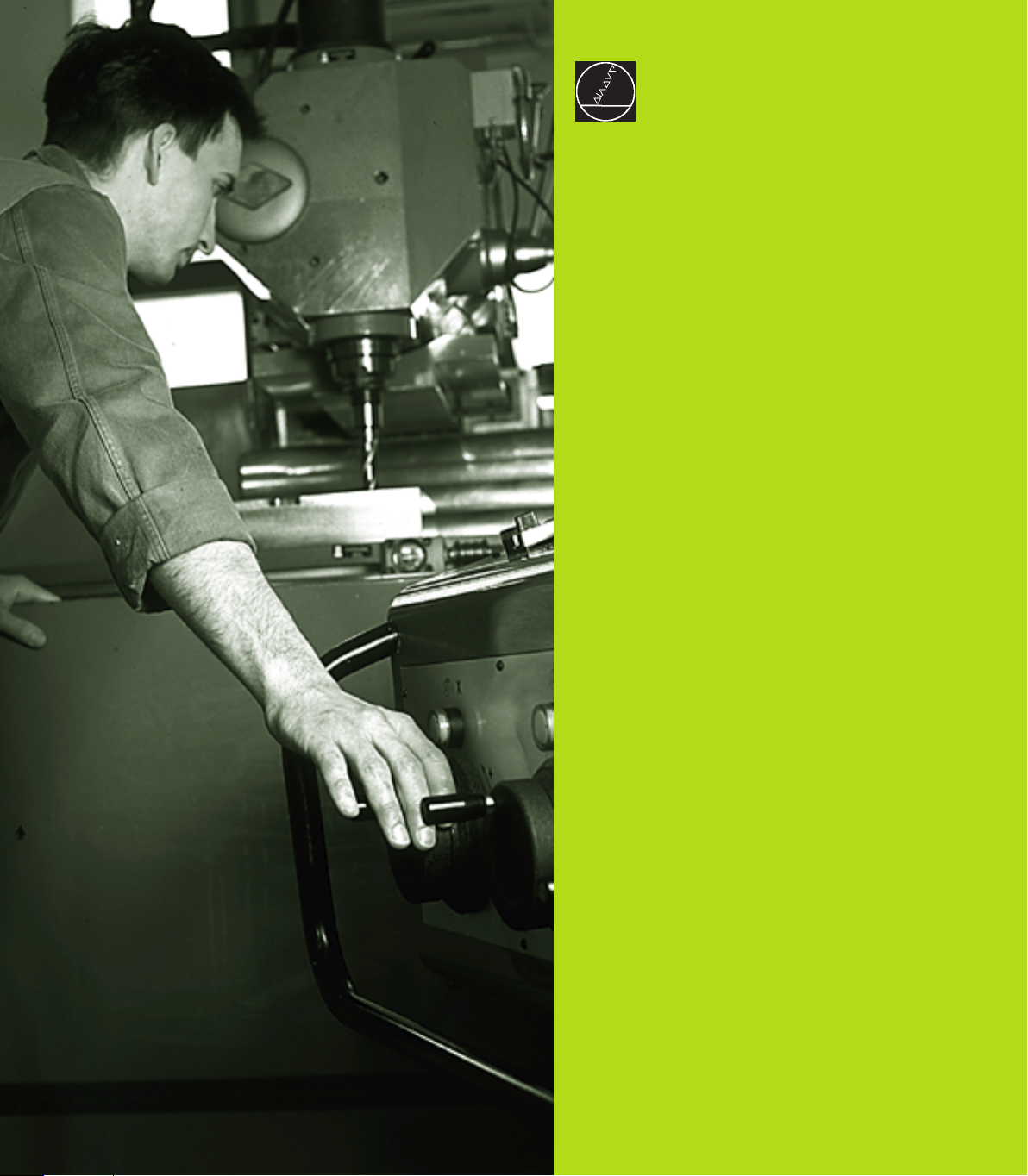
HR electronic handwheels
Electronic handwheels facilitate moving the axis slides precisely by
hand. A wide range of traverses per handwheel revolution is
available. Apart from the HR 130 and HR 150 integral handwheels,
HEIDENHAIN also offers the HR 410 portable handwheel (see
figure at right).
1.5 Accessories: HEIDENHAIN 3-D Touch Probes and Electronic Handwheels
Manual Operation and Setup
2
14
The reference points need only be
traversed if the machine axes are to be
moved. If you intend only to write, edit or
test programs, you can select the
Programming and Editing or Test Run
modes of operation immediately after
switching on the control voltage.
You can then traverse the reference
points later by pressing the PASS OVER
REFERENCE soft key in the Manual
Operation mode.
Traversing the reference point in a tilted working
plane
The reference point of a tilted coordinate system
can be traversed by pressing the machine axis
direction buttons. The “tilting the working plane”
function (see section 2.5 “Tilting the Working
Plane”) must be active in the Manual Operation
mode. The TNC then interpolates the corresponding
axes.
The NC START button is not effective. Pressing this
button may result in an error message.
Make sure that the angle values entered in the
menu for tilting the working plane match the actual
angle of the tilted axis.
Switch-off
To prevent data being lost at switch-off, you need to
run down the operating system as follows:
ú Select the Manual mode
ú Select the function for run-down,
confirm again with the YES soft key.
ú When the TNC displays the message
„Now you can switch off the TNC“ in a
superimposed window, you may cut
off the power supply to the TNC.
Inappropriate switch-off of the TNC can
lead to data loss.
2.1 Switch-on, Switch-off
2 Manual Operation and Setup
2.1 Switch-on, Switch-off
Switch-On
Switch-on and traversing the reference points can vary
depending on the individual machine tool. Your machine
manual provides more detailed information.
Switch on the power supply for control and machine.
The TNC automatically initiates the following dialog
Memory Test
<
The TNC memory is automatically checked.
Power Interrupted
<
TNC message that the power was interrupted
— clear the message.
Translate PLC Program
<
The PLC program of the TNC is automatically compiled.
Relay Ext. DC Voltage Missing
<
Switch on the control voltage.
The TNC checks the functioning of the
EMERGENCY STOP circuit.
Manual Operation
Traverse Reference Points
<
Cross the reference points manually in the
displayed sequence: For each axis press the
machine START button, or
cross the reference points in any sequence:
Press and hold the machine axis direction
button for each axis until the reference point has
been traversed.
The TNC is now ready for operation in the
Manual Operation mode.
 Loading...