


User’s Manual
ND 710
ND 750
Position Display Units for Milling Machines
English (en) 12/2001
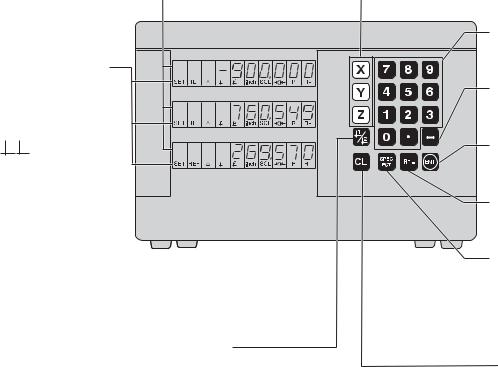
Position display |
• Select coordinate axes |
(ND 710 only two axes) |
(ND 710 only X and Y) |
|
• Select axis-specific operating parameters |
Status display:
SET = Datum setting REF = blinking:
Traverse the reference points. On continuously: Reference points
have been traversed. D = Distance-to-go display 1 2 Datum 1 or 2
Inch = Display in inches
SCL = Scaling factor
-> <- = Touching the edge / centerline
R = Radius/diameter HEIDENHAIN display
R+/– = Radius compensation
•Select datum 1 or 2
•Page backward in the list of special functions
•Page backward in the list of parameters
Numerical input
•Change the algebraic sign
•Call the last dialog
•Edit parameters in the list of parameters
•Confirm entry
•Page forward in the list of parameters
Call radius compensation of the current tool
•Select special functions
•Page forward in the list of special functions
•Cancel entry
•Reset the operating mode
•Zero the selected axis (if activated in P80)
•Select parameters:
CL plus two-digit number

This manual is for the ND display units with the following software numbers or higher:
ND 710 for two axes |
246 271-07 |
ND 750 for three axes |
246 271-07 |
About this manual
This manual is divided into two parts:
Part I: Operating Instructions
•Fundamentals of positioning
•ND functions
Part II: Installation and Specifications
•Mounting the display unit on the machine
•Description of operating parameters
Part I Operating Instructions
Fundamentals |
|
4 |
|
|
|
Switch-On, Traversing the Reference Points |
9 |
|
|
|
|
Datum Setting |
|
10 |
|
|
|
Tool Compensation |
|
19 |
|
|
|
Moving the Axes with Distance-To-Go |
|
20 |
|
|
|
Bolt Hole Circles and Bolt Hole Circle Segments |
22 |
|
|
|
|
Linear Hole Patterns |
|
25 |
|
|
|
Working with a Scaling Factor |
|
28 |
|
|
|
Error Messages |
|
29 |
|
|
|
Part II |
|
|
Installation and |
Page 31 |
|
Specifications |
and following |
|
Part I Operating Instructions
3
Fundamentals |
Fundamentals |
|
|
||
You can skip this chapter if you are already familiar with |
||
|
||
|
coordinate systems, incremental and absolute dimensions, |
|
|
nominal positions, actual positions and distance-to-go. |
|
|
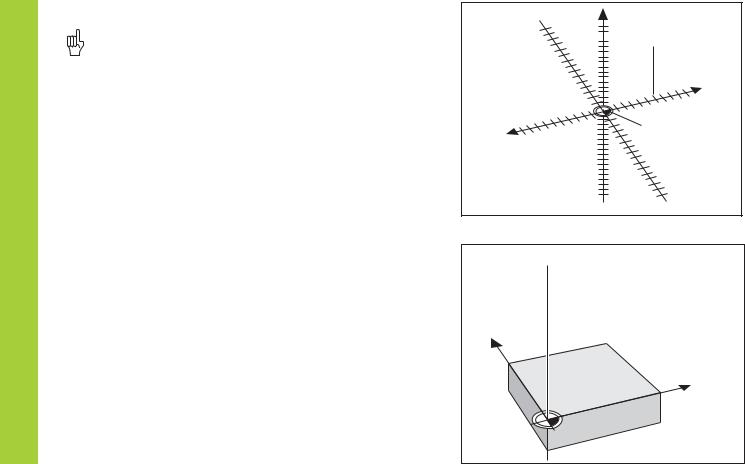
Coordinate system |
|
|
To describe the geometry of a workpiece, the Cartesian* coordinate |
|
|
system is used. The Cartesian coordinate system consists of three |
|
|
mutually perpendicular axes X, Y and Z. The point of intersection of |
|
|
these axes is called the datum or origin of the coordinate system. |
Think of the axes as scales with divisions (usually in millimeters) which allow us to fix points in space referenced to the datum.
To determine positions on a workpiece, the coordinate system is “laid” onto the workpiece.
The machine axes are parallel to the axes of the coordinate system. The Z axis is normally the tool axis.
4 |
1) |
Named in honor of the French mathematician and philosopher |
|
René Descartes (1596 to 1650) |
+Y +Z
+Z
 Graduation
+X
–X |
Datum or |
|
origin |
–Z
 –Y
–Y
Z
Y
X

Datum setting
The workpiece drawing is used as the basis for machining the workpiece. To enable the dimensions in the drawing to be converted into traverse distances of machine axes X, Y and Z, each drawing dimension requires a datum or reference point on the workpiece (since a position can only be defined in relationship to another position).
The workpiece drawing always indicates one absolute datum (the datum for absolute dimensions). However, it may contain additional relative datums.
In the context of a numerical position display unit, datum setting means bringing the workpiece and the tool into a defined position in relation to each other and then setting the axis displays to the value which corresponds to that position. This establishes a fixed relationship between the actual positions of the axes and the displayed positions.
You can set 9 absolute datum points and store them in nonvolatile memory.
1225 
750 
320 
0 
Absolute datum
-250 |
-216,5 |
-125 |
0 |
125 |
216,5 |
250 |
|
|
|
|
|
|
|
216,5 |
250 |
|
|
|
|
|
|
|
|
|
|
|
|
|
|
125 |
|
|
|
|
|
|
|
0 |
|
|
|
|
|
|
|
-125 |
|
|
|
|
|
|
|
-216,5 |
-250 |
|
|
|
|
|
|
|

 150 0
150 0
300±0,1 |
-150 |
|
|
Relative |
0 |
|
datums |
||
0 |
325 |
450 |
700 |
900 950 |
Fundamentals
5
Fundamentals
6
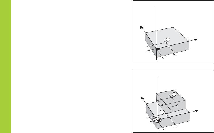
Absolute workpiece positions
Each position on the workpiece is uniquely defined by its absolute coordinates.
Example |
Absolute coordinates of position 1: |
||
|
X |
= |
10 mm |
|
Y |
= |
5 mm |
|
Z |
= |
0 mm |
If you are working according to a workpiece drawing with absolute dimensions, then you are moving the tool to the coordinates.
Relative workpiece positions
A position can also be defined relative to the previous nominal position. The datum for the dimension is then located at the previous nominal position. Such coordinates are termed relative coordinates or chain dimensions. Incremental coordinates are indicated by a preceding I.
Example |
Relative coordinate of position 2 referenced to |
|
|
position 1: |
|
|
IX = |
10 mm |
|
IY = |
10 mm |
If you are working according to a workpiece drawing with incremental dimensions, then you are moving the tool by the dimensions.
Sign for incremental dimensioning
A relative dimension has a positive sign when the axis is moved in the positive direction, and a negative sign when it is moved in the negative direction.
Z 
Y
X
1
5 

 10
10
Z
Y |
2 |
|
10 |
10 |
X |
11
5 
 10
10

Nominal position, actual position and distance-to-go
The position to which the tool is to move is called the nominal position ( S ). The position at which the tool is actually located at any given moment is called the actual position ( I ).
The distance from the nominal position to the actual position is called the distance-to-go ( R ).
Sign for distance-to-go
When you are using the distance-to-go display, the nominal position becomes the relative datum (display value 0). The distance-to-go is therefore negative when you move in the positive axis direction, and positive when you move in the negative axis direction.
Z 
S
I
R
Y
X
Fundamentals
7

Fundamentals
8
Position encoders
The position encoders on the machine convert the movements of the machine axes into electrical signals. The ND display unit evaluates these signals, determines the actual position of the machine axes and displays the position as a numerical value.
If the power is interrupted, the relationship between the machine axis positions and the calculated actual positions is lost. The reference marks on the position encoders and the REF reference mark evaluation feature enable the ND to quickly re-establish this relationship again when the power is restored.
|
Z |
Y |
Workpiece |
|
|
|
X |
|
Position |
|
encoder |
Reference marks
The scales of the position encoders contain one or more reference marks. When a reference mark is crossed over, a signal is generated which identifies that position as a reference point (scale datum = machine datum).
When this reference mark is crossed over, the ND's reference mark evaluation feature (REF) restores the relationship between axis slide positions and display values which you last defined by setting the datum. If the linear encoders have distance-coded reference marks, you only need to move the machine axes a maximum of 20 mm to do this.
Scale in |
Distance-coded |
linear encoder |
reference marks |
Reference mark
Switch-On, Traversing the Reference Marks
0 1 |
Turn on power (switch located on rear panel). |
REF and decimal points in status display blink. |
ENT...CL
ENT |
Confirm reference traverse mode. REF remains |
|
on continuously. Decimal points blink. |
Cross over the reference marks in all axes (in any sequence). Each axis display becomes active when its reference mark is crossed over.
Crossing over the reference marks stores the last relationship between axis slide positions and display values for datum points 1 and 2 in nonvolatile memory.
Note that if you choose not to traverse the reference marks (by clearing the dialog ENT ... CL with the CL key), this relationship will be lost if the power is interrupted or when the unit is switched off.
Switch-On, Traversing the Reference Marks
If you wish to use multipoint axis error compensation you |
|
must traverse the reference marks (see “Multipoint axis error |
9 |
compensation”)! |

Datum Setting
Datum Setting
If you want to save the datum points in nonvolatile memory, you must first cross over the reference marks.
Only after crossing over the reference marks can you set new datums or activate existing ones.
In P70, you can select:
•Two datum points: The selected datum
is displayed via 1 or 2
•Nine datum points: The selected datum is displayed in the lowest axis via d1 to d9.
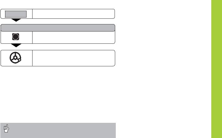
There are several ways to set datums:
Touch the edge of the workpiece with the tool and then set the desired datum. You can also touch two edges and set the centerline between them as a datum, or touch the inside of a circle and set the circle center as a datum (see examples). The tool data of the tool used for this are automatically considered (see “Tool Compensation”).
To call a datum point you have set, proceed as follows:
You have set two datum points in P70:
Select datum 1 or 2.
You have set nine datum points in P70:
Press the datum key (“d” blinks).
Enter a datum number (1 to 9).
1ENT
10
Probing a workpiece edge to find a datum
The ND display units support the following probing functions:
“PROBE EDGE” |
Setting a workpiece edge as datum. |
“PROBE MIDPOINT” Setting a midpoint between two workpiece edges as datum.
“PROBE CIRCLE” |
Setting the center of a circle as datum. |
The probing functions are accessible in the SPEC FCT mode of operation.
The functions “PROBE EDGE”, “PROBE MIDPOINT” and “PROBE CIRCLE” are described on the following pages.
Datum setting with the tool
Example:
Working plane |
X / Y |
Tool axis |
Z |
Tool radius |
R = 5 mm |
Axis sequence |
X – Y – Z |
for datum setting |
|
Z 
 R=5mm
R=5mm
Y
X
1
2
Datum Setting
11

Datum Setting
Probing a workpiece edge to find a datum
Select a datum number (see page 10).
SPEC
FCT
SPEC or
FCT
PROBING
ENT
PROBE EDGE
ENT
X
•
•
Select the special functions.
Select the “probing function.”
Confirm selection.
Confirm “Probe edge.”
Select the X axis (if not already selected). SET lights. The <- status symbol starts to blink.
PROBE X
ENT
(appears only briefly))
Touch workpiece edge 1 with the tool.
X position is captured. “SET edge“ appears briefly. SET starts to blink. Retract tool from workpiece.
The <- status symbol lights.
0 |
• |
ENT |
Enter position value for the datum. |
Tool radius is automatically |
|||
|
• |
|
compensated. |
|
• |
|
|
|
|
|
YSelect the Y axis. SET lights.
The <- status symbol starts to blink.
PROBE Y (appears only briefly)
Touch workpiece edge 2 with the tool.
•
•
12
Y position is captured. “SET
ENT edge“appears briefly. SET starts to blink. Retract tool from workpiece.
The <- status symbol lights.
Enter position value for the datum in the 0 ENT Y axis. Tool radius is automatically
compensated.
Z |
Select the Z axis. SET lights. |
1) |
|
||
The <- status symbol starts to blink. |
|
|
|
|
|
|
|
|
PROBE Z (appears only briefly)
Touch workpiece surface with the tool.
Z position is captured. “SET edge“
ENT appears briefly. SET starts to blink.
Retract tool from workpiece.
The <- status symbol lights.
•
•
1) only with ND 750
0ENT
SPEC |
or CL |
FCT |
Enter position value for the datum in the Z axis.
After setting the datum, exit the probing funtions.
Datum Setting
13

Datum Setting
Probing workpiece edges to find a midpoint datum |
|
||
|
|
Z |
|
The edges to be probed run parallel to the Y axis. |
|
||
Follow the procedure below for all midpoints between two edges: |
|
||
|
|
Y |
2 |
|
|
Select a datum number (see page 10). |
|
|
|
|
|
|
|
1 |
M |
|
|
|
X? |
|
|
|
X |
|
SPEC |
Select the special functions. |
|
|
FCT |
|
|
SPEC |
or |
Select the probing function. |
|
FCT |
|
|
|
PROBING
Confirm selection.
ENT
•
•
•
14
 Loading...