


ND 530
Working with the position
HEIDENHAIN
display unit
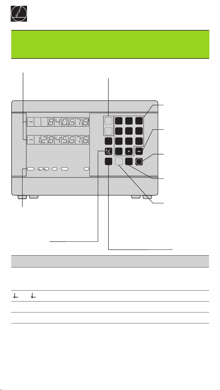
Actual value and input display
(7-segment LED, 8 decades and
sign); upper display: X axis;
lower display: Z axis
ND 530
• Select coordinate axis
• Select axis-specific operating parameters
Numeric keypad
and decimal point
1
REF
HEIDENHAIN
Status indicators
2
in. SCL R
• Select datum
• Page backward in
parameter list
X
7
4
Z
1
1
0
2
R
CL
x
x
• Clear entry
• CL plus two-digit number:
select parameter
• Clear parameter entry
MOD
9
8
5
6
3
2
ENT
• Sign
• Change parameter
Confirm entry
• Call operating
parameters
• Page forward in
parameter list
Select radius
display for X axis
Indicator Meaning
REF Reference mark crossed over – datum points are now stored in
nonvolatile memory.
Blinking: Waiting for confirmation from operator.
1 / 2 Datum point 1 / Datum point 2 currently active.
in. Position values displayed in inches
SCL Scaling factor active
R
x
Radius display for X axis active
The ND 530 display unit for lathes is designed for use with two HEIDENHAIN linear
encoders with sinusoidal output signals.
The linear encoders have one reference mark or several (preferably distance-coded)
reference marks. When a reference mark is crossed over, a signal is generated which
identifies that position as a reference point.
After switch-on, crossing over the reference marks restores the relationship between
axis slide positions and display values last established by datum setting. With encoders that have distance-coded reference marks, this requires a traverse of no more
than 20 mm.
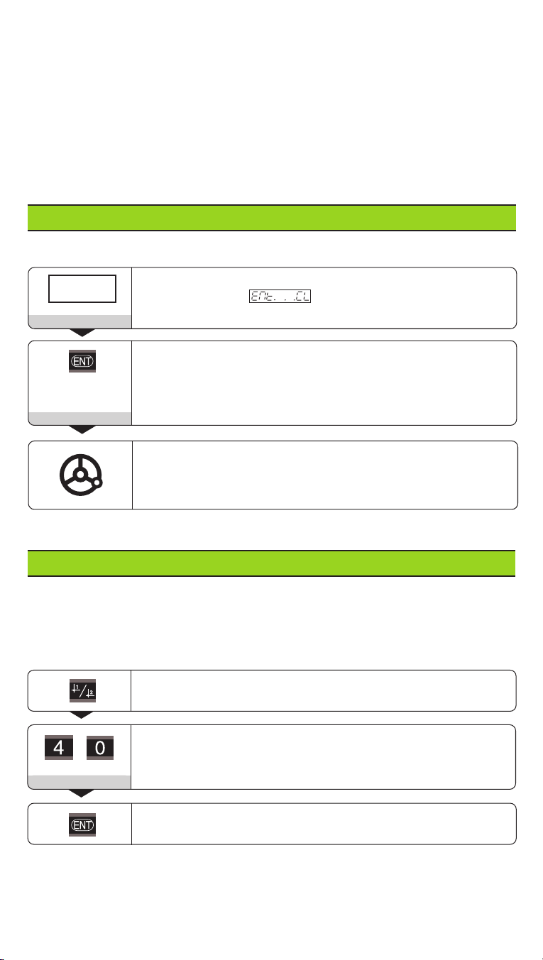
Switch-On
0 ➤1
Ent...CL
5 , 6 9 7
If you do not wish reference mark evaluation, press CL instead of ENT.
Turn on the display unit (switch located on rear panel).
• Display shows .
• REF blinks.
Switch on reference mark evaluation.
• The display shows the value last assigned to the reference
mark position.
• REF glows.
• The decimal point blinks.
Cross over the reference mark.
Move the axis until the display becomes active and the decimal
point stops blinking.
The display unit is now ready for operation.
Datum Setting
The datum setting procedure assigns a specific axis position to the associated display
value. For example, you can set the workpiece face to Z = 0 mm and a shoulder on
the workpiece to its associated X coordinate.
You can set two separate datum points.
Select datum point 1 or 2.
Enter a numerical value, such as 40.
4 0
Confirm your entry.
You can switch from one datum point to the other at any time.
Use datum point 2 if you want to display incremental dimensions.
Radius Display for the X Axis
There are two ways to switch the X axis from diameter to radius display:
• Operating parameter or
• The Rx key.
When Rx lights up the radius display is active.
Working with Scaling Factors
The ND 510 and the ND 550 can display the axis traverse lengthened or shortened
by a scaling factor. You enter a scaling factor separately for each axis in the user
parameter P12, then activate the scaling factor function with the user parameter
P11. SCL is highlighted.
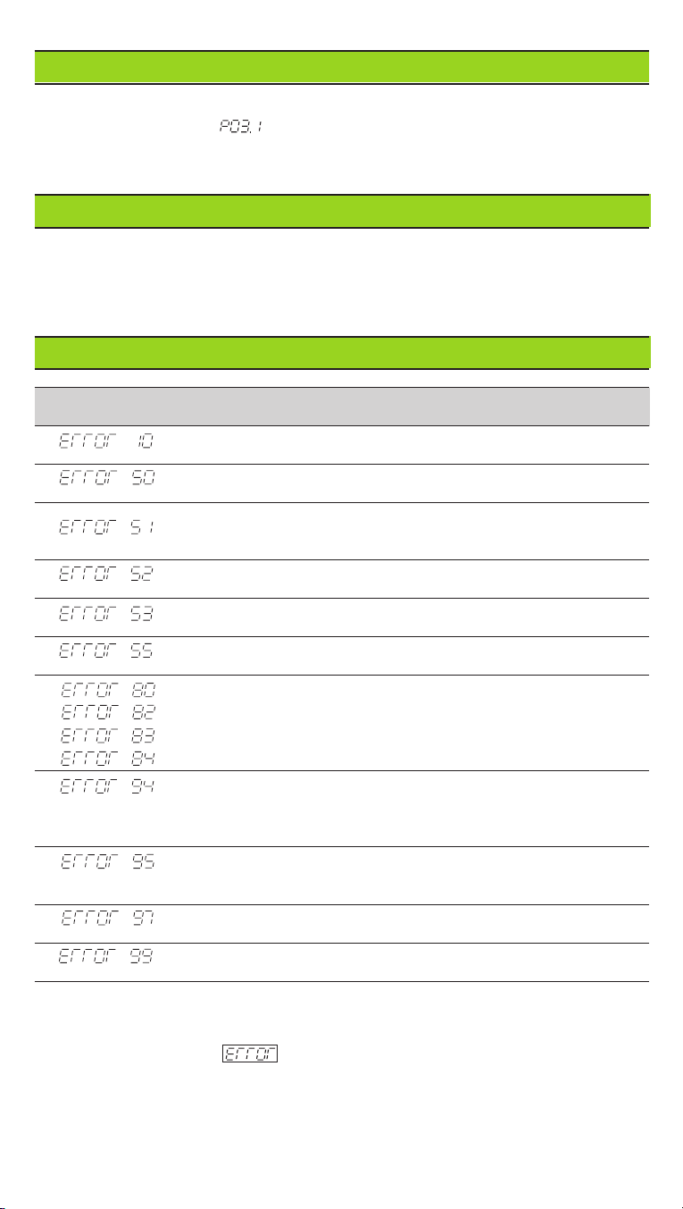
Error Messages
Message Cause and effect
Incorrect input value
Encoder signal too weak (encoder may be contaminated)
Input frequency too high for encoder input
(will occur for example when traverse speed too high)
Encoder signal to strong
Internal counter overflow
Error while crossing over reference marks
To clear the error message: Switch off the display unit.
Should any of these error codes recur,
contact your HEIDENHAIN service agency.
Offset compensation values for encoder signals have been
erased:
contact your service agency.
Compensation values for nonlinear axis error compensation have
been erased
Datums have been erased
Erase the operating parameters.
If all decimal points light up, the measured value is too large or too small.
Set a new datum.
To clear error message :
When you have removed the cause of the error,
➤ press CL.
 Loading...