


 Loading...
Addendum
IK 5000 QUADRA-CHEK
Software Version 3.0.x
English (en) 12/2013
Information contained in this manual
This addendum covers the operating and setup feature additions and improvements implemented in IK 5000 Software v3.0.x. For OEM setup feature additions refer to the IK 5000 QUADRA-CHEK OEM Addendum (ID 1041353-2x), available by request from HEIDENHAIN.
Minimum system requirements
Component |
w/o 3D Profiling |
w/ 3D Profiling |
PC |
2.66 GHz dual-core Pentium |
2.8 GHz quad-core Pentium |
|
|
|
Operating System (OS) |
Windows XP |
|
|
Windows Vista 32-bit |
|
|
Windows 7 32-bit, Windows 7 64-bit |
|
|
Windows 8 32-bit, Windows 8 64-bit |
|
|
|
|
RAM |
1GB |
2GB |
|
|
|
Available Hard Disk |
500MB |
1GB |
|
|
|
PCI |
1 PCI slot and 1 to 3 additional empty slots (depending on the version) |
|
|
|
|
|
Note: PCI Express slot required for PC2-COMP Express frame grabber board, refer to "PC2- |
|
|
COMP Express frame grabber board on page 80”. The PC2-COMP Express frame grabber |
|
|
board is compatible with 32-bit operating systems only. |
|
|
|
|
Video Display Unit |
1024 x 768 resolution |
|
|
|
|
Windows users rights |
Administrator |
|
Backward compatibility
The IK 5000 QUADRA-CHEK v3.0.x software version is compatible with several previous versions down to version 2.93.0. It can be used to update any prior version starting at version 2.93.0 and up. To update a previous version refer to “Software Updates” below.
Software updates
End users should only update the IK 5000 software after consultation with the machine manufacturer. Observe the system requirements as described in “Minimum System Requirements” above. For software updating procedures, refer to " Updating the IK 5000 software on page 78”.
Fonts used in these instructions
Items of special interest or concepts that are emphasized to the user are shown in bold type.
Software controls and Windows are shown in letter gothic bold type.
IK 5000 QUADRA-CHEK |
3 |
4 |
Preface |

1 Operation ..... |
9 |
1.1 Operation |
..... 10 |
|
|
|
|
|
|
|
|
|
Adjusting for change of part size ..... |
10 |
|
|
|
|
|||||
|
Part scaling example ..... |
11 |
|
|
|
|
|
|||
Auto probe a plane |
..... |
12 |
|
|
|
|
|
|
||
|
Grid pattern auto probe ..... |
12 |
|
|
|
|
||||
|
Disc pattern auto probe ..... |
13 |
|
|
|
|
||||
Programming changes |
..... 14 |
|
|
|
|
|
||||
Programming wizards ..... |
15 |
|
|
|
|
|
|
|||
|
Grids ..... |
15 |
|
|
|
|
|
|
|
|
|
Polar grids ..... |
19 |
|
|
|
|
|
|
||
|
Palletize ..... |
|
21 |
|
|
|
|
|
|
|
|
Random placement ..... |
24 |
|
|
|
|
|
|||
Additional tolerance check Axial Runout for Plane feature |
..... 34 |
|||||||||
Palletizing multiple parts ..... |
35 |
|
|
|
|
|
||||
Profile import points ..... |
36 |
|
|
|
|
|
|
|||
Measuring rectangles ..... |
38 |
|
|
|
|
|
|
|||
Profile3D measurements ..... |
39 |
|
|
|
|
|
||||
|
Profile3D measurement screen functions |
..... |
40 |
|
||||||
|
Profile3D window menu ..... |
41 |
|
|
|
|
||||
|
The Profile3D measurement process ..... |
42 |
|
|
||||||
|
Start Profile3D measurement ..... |
43 |
|
|
|
|||||
|
Import part profile ..... |
43 |
|
|
|
|
|
|||
|
Enable or prohibit data shifts for Profile3D fit |
..... 45 |
||||||||
|
Assign tolerances ..... |
46 |
|
|
|
|
|
|||
|
Probe part surfaces ..... |
48 |
|
|
|
|
|
|||
|
Perform Profile3D fit analysis ..... |
49 |
|
|
|
|||||
|
Profile3D automatic fit analysis ..... |
50 |
|
|
|
|||||
|
Profile3D Pass Only option ..... |
51 |
|
|
|
|||||
|
Six point alignment ..... |
52 |
|
|
|
|
|
|||
|
Resetting the fit analysis ..... |
53 |
|
|
|
|
||||
|
Adjust the display magnification of error whiskers |
..... 54 |
||||||||
|
Add Profile3D feature to the Feature template ..... |
55 |
||||||||
IK 5000 QUADRA-CHEK |
5 |
Auto Focus (option) ..... |
57 |
|
|
||
Autofocus final check ..... |
60 |
|
|
||
Exploding the Data Cloud ..... |
61 |
|
|
||
Rotating and positioning of VED tools using part reference frame ..... |
62 |
||||
ISO Tolerance ..... |
62 |
|
|
|
|
Continuous probe firing ..... |
66 |
|
|
||
Programming continuous probe firing ..... |
67 |
|
|||
Initial settings step |
..... 67 |
|
|
||
Program step ..... |
68 |
|
|
||
Measure shortcuts ..... |
69 |
|
|
|
|
Ellipse shortcut ..... |
|
69 |
|
|
|
Torus shortcut ..... |
|
69 |
|
|
|
Profile shortcut ..... |
|
69 |
|
|
|
Profile3D shortcut ..... |
69 |
|
|
||
Symmetry tolerance ..... |
70 |
|
|
||
Symmetry tolerance applied to a line ..... |
70 |
|
|||
Symmetry tolerance applied to a plane ..... |
72 |
|
|||
Plane probing technique ..... |
74 |
|
|
||
6

2 Setup ..... |
77 |
2.1 Setup ..... |
78 |
|
|
|
|
|
|
|
|
Updating the IK 5000 software ..... |
78 |
|
|
|
|
||||
|
Backup system settings ..... |
78 |
|
|
|
|
|||
|
Uninstall old software version ..... |
78 |
|
|
|
||||
|
Install new software version ..... |
78 |
|
|
|
||||
|
Restore system settings ..... |
78 |
|
|
|
|
|||
Files and folders ..... |
79 |
|
|
|
|
|
|
||
PC2-COMP Express frame grabber board ..... |
80 |
|
|
||||||
Use current reference frame ..... |
81 |
|
|
|
|
||||
Camera parameters |
..... 83 |
|
|
|
|
|
|
||
Specify video probe parameters ..... |
84 |
|
|
|
|
||||
Spotter camera options ..... |
85 |
|
|
|
|
|
|||
Scale factor for Open Loop joystick control (Optional) ..... |
87 |
||||||||
Shutdown ..... |
89 |
|
|
|
|
|
|
|
|
Debounce parameters ..... |
90 |
|
|
|
|
|
|||
Touch probe requalification and starting point |
..... |
91 |
|
||||||
Reset template text colors |
..... 92 |
|
|
|
|
||||
Default fixtures files location ..... |
93 |
|
|
|
|
||||
External amplifier Open Loop control (Optional) ..... |
94 |
|
|||||||
|
Joystick button assignment ..... |
95 |
|
|
|
||||
IK 5000 QUADRA-CHEK |
7 |
8

Operation

 1.1 Operation
1.1 Operation
Adjusting for change of part size
The location of features in a part under measure can change due to change in size of the part. A program can adjust to measure the features at the new locations by using the Prompt user for part scaling function. This function prompts the user for a scaling factor that repositions all features in a program. The new feature position is calculated using the recorded feature position multiplied by the scaling factor. The scaling factor is prompted for each time the program is run.
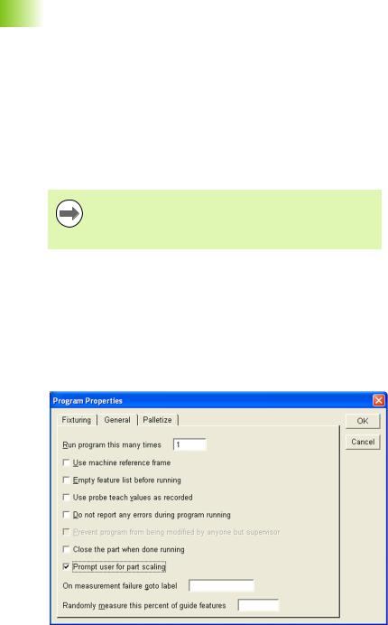
The Prompt user for part scaling function is located in the General tab of the Program Properties dialog.
The size of the features under measure in the program are not altered by the part scaling function, hence the system will probe the features at the recorded size but new scaled position.
To prompt a user for part scaling:
Start recording a program
Double click Program Properties in the Program template window
Click the General tab
Check the check box next to Prompt user for part scaling and then click OK
The operator will now be prompted to enter a scaling factor when the program is run.
Selecting Prompt User for Part Scaling
10 |
1 Operation |
Part scaling example
This example shows measurement results before and after part scaling has been applied.
Start recording a program
Measure a feature and note the position of the feature
Feature measurement results
Stop recording the program
Activate Prompt user for part scaling as described on page 10.
Run the recorded program. A prompt will appear requiring the user to enter a part scaling factor.
Enter Part Scaling prompt
Re-measure the feature and complete program execution
Note that the program feature CIRCLE 2 will now be probed at a position scaled by a factor of 0.500 (X=4.00000, Y=2.50000, Z=0.00000)
1.1 Operation
IK 5000 QUADRA-CHEK |
11 |


 1.1 Operation
Auto probe a plane
Plane measurement accuracy is increased by probing more than the three required points. IK 5000 systems with CNC and touch probe options can automatically probe multiple points by using the
Auto Probe Plane feature in the Measure Plane Dialog.
To auto probe a plane:
Click the Auto Probe... button in the Measure Plane dialog.The
Auto Probe Plane dialog appears.
Select the Grid or DISC tab
Probe the required positions and enter the required parameters
Click OK
Grid pattern auto probe
4
1
5 |
3 |
2
Grid dialog |
|
Grid pattern |
|
|
|
|
|
|
Parameter |
Description |
|
1 |
Corner position 1 |
The first corner position in the grid |
|
|
|
|
|
2 |
Corner position 2 |
The second corner position in the |
|
|
|
grid |
|
|
|
|
|
3 |
Corner position 3 |
The third corner position in the grid |
|
|
|
|
|
4 |
# Points on longer side |
The number of points on the longest |
|
|
|
side of the grid |
|
|
|
|
|
5 |
# Points on shorter |
The number of points on the |
|
|
side |
shortest side of the grid |
|
|
|
|
|
|
Normal position |
A position above the plane for the |
|
|
|
probe to retract to after probing a |
|
|
|
point |
|
|
|
|
|
12 |
1 Operation |
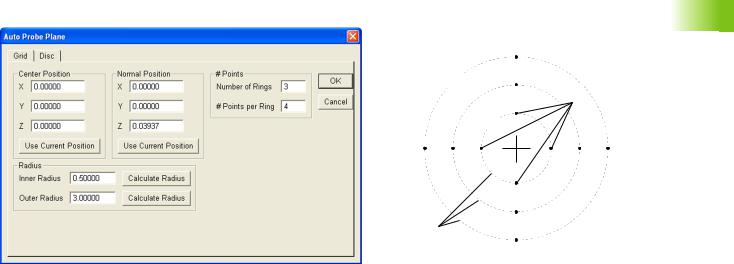
Disc pattern auto probe
5
3
4
1
|
|
|
|
2 |
|
Disc dialog |
|
Disc pattern |
|||
|
|
|
|||
|
Parameter |
Description |
|
||
1 |
Center position |
The center position of the disc pattern |
|
||
|
|
|
|
||
2 |
Number of rings |
The number of rings in the pattern |
|||
|
|
|
|
||
3 |
# Points per ring |
The number of points probed per ring |
|||
|
|
|
|
||
4 |
Inner radius |
The radius of the inner ring of the pattern |
|||
|
|
|
|
||
5 |
Outer radius |
The radius of the outer ring of the pattern |
|||
|
|
|
|
||
|
Normal position |
A position above the plane for the probe |
|||
|
|
to retract to after probing a point |
|||
|
|
|
|
|
|
1.1 Operation
IK 5000 QUADRA-CHEK |
13 |


 1.1 Operation
Programming changes
While recording a program that is intended to include a looping function (such as a loop, grid, polar grid, palletize or random placement), it is important to record the entire program with the looping function before completing the program and running or editing it. This ensures proper handling of any datum steps in the loop, if any, and proper insertion of offset recall tags.
Tags are not displayed in the program.
When a feature is under measure during program playback, that feature is now removed from the feature list. Previously, the recorded feature was maintained in the feature list during measurement and replaced by the newly measured feature once the measurement was completed.
Grids, polar grids, palletizations and random placements are described in Programming wizards on page 15.
14 |
1 Operation |

Programming wizards
Use programming wizards to create the following program steps:
Grids
Polar grids
Palletizations
Random placements
Grids
Use the Create a Grid wizard to measure arrays or a series of like features within a single part. For example, create a grid to measure an array of evenly spaced holes on a pc board. The IK 5000 requires the user to input the X and Y offset distance, the X and Y distance from one feature to the next.
All features in a grid must be evenly spaced.
Before creating a grid begin a new part program with a datum.
To create a grid:
Position the first array feature as shown
1.1 Operation
IK 5000 QUADRA-CHEK |
15 |

 1.1 Operation
Click the center mouse button to fire the probe tool
Click OK in the dialog box
16 |
1 Operation |

Highlight the first array feature in the Program template as shown
Right-click in the Program template and select Programming Wizards, then select Create a Grid
1.1 Operation
IK 5000 QUADRA-CHEK |
17 |

 1.1 Operation
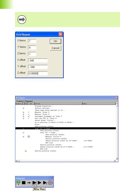
Enter the number of features and type in the desired X and Y offsets as shown
Items are the number of features in each axis direction. Offsets are the distance to the next feature relative from previous feature.
Click OK in the dialog box
The grid is created and the program is ready to run
Click New Run to run the program
18 |
1 Operation |

Polar grids
A polar grid measures a part with like features that are in a rotational array. For example, create a polar grid to measure a bolt hole pattern. The programming wizard that creates a polar grid requires the user to input the number of features and the angle between the features.
All features in a polar grid must be evenly spaced.
Before creating a polar grid, create a new part program. Use the center of the polar grid features as the zero point of the part.
Make certain the program is recording before completing the following steps.
To create a polar grid:
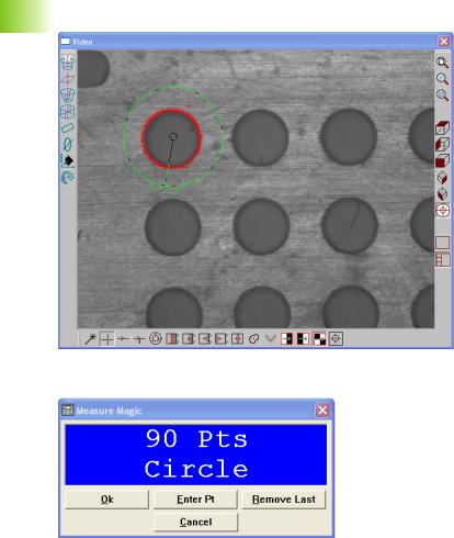
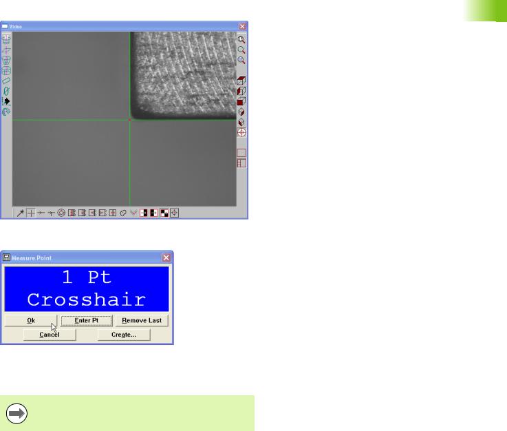
Position the first feature in the polar array in the center of the field of view as shown
1.1 Operation
IK 5000 QUADRA-CHEK |
19 |


 1.1 Operation
Select Measure>Circle
Click Enter Point in the Measure Circle dialog
Click OK
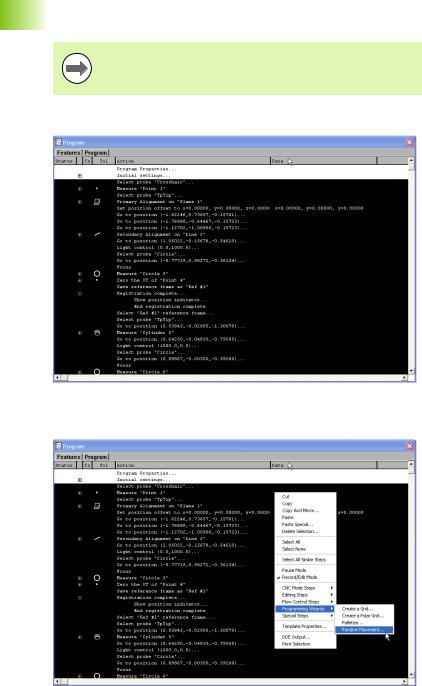
Select the measured Circle in the Program template
Select Tools>Programming>Programming Wizards>Create a Polar
Grid
Enter the number of times to loop in the Times to Repeat field
Enter the loop increment angle in the Angle Increment field
Click OK
The polar grid is created and the program is ready to run.
20 |
1 Operation |
Palletize
Use the Palletize wizard for measuring multiple parts placed on a precision fixture.
All palletized parts must be in a fixture that evenly spaces the individual parts.
Before palletizing parts, create a new part program measuring all the features of the part.
Save the reference frame in the part program immediately after creating the datum.
Make certain the program is recording before completing the following steps.
To palletize multiple parts:
Highlight the desired features as shown
1.1 Operation
IK 5000 QUADRA-CHEK |
21 |


 1.1 Operation
Right-click in the Program template and select Programming Wizards, then select Palletize
Enter the number of features and type in the desired X and Y offsets as shown
Items are the number of parts in each axis direction. Offsets are the distance to the next part relative from previous part.
22 |
1 Operation |

Click OK in the dialog box
The palletization is completed and the program is ready to run.
Click New Run to run the program
1.1 Operation
IK 5000 QUADRA-CHEK |
23 |


 1.1 Operation
Random placement
Use the Random Placement wizard for multiple parts on a stage without a fixture.
All parts must have the same orientation on the stage and be square to the axes of the machine.
Before creating a random placement, create a new part program with reference steps.
Reference steps
To insert reference steps in a part program:
Click the Record/Edit button on the Program toolbar
Position the desired reference feature as shown
The reference feature is a repeatable point to help the IK 5000 locate the randomly placed parts.
24 |
1 Operation |
Click the center mouse button to fire the probe tool
Click OK in the dialog
The IK 5000 will use this feature to locate the randomly place parts.
Create a the rest of the part program measuring all the features of the part.
Save the reference frame in the part program immediately after creating the datum.
1.1 Operation
IK 5000 QUADRA-CHEK |
25 |

 1.1 Operation
Random Placement
To create a random placement:
Make certain the program is recording before completing the following steps.
Highlight the desired features, and the reference point as shown
Right-click in the Program template and select Programming Wizards, then select Random Placement
26 |
1 Operation |

The IK 5000 inserts the required steps for the random placement.
To run a parts program with a random placement:
Click the New Run button on the Program toolbar
1.1 Operation
IK 5000 QUADRA-CHEK |
27 |


 1.1 Operation
Measure the reference point for the first part
Repeat these steps until all parts are entered.
Click OK in the dialog box
Click the Remove Last button to remove the last point enter. Reenter the point for that part.
Click the Use Last Run button to use the same offsets as the previous run.
28 |
1 Operation |

Copy and paste special
Before performing a copy and paste special, record a new part program with a datum.
To copy and paste special:
Position the first array feature as shown
Click the center mouse button to fire the probe tool
1.1 Operation
IK 5000 QUADRA-CHEK |
29 |


 1.1 Operation
Click OK in the dialog box
Highlight the first array feature in the Program template as shown
Right-click in the Program template and select Copy
30 |
1 Operation |
Loading...