


 Loading...
Operating Instructions
ND 2100G GAGE-CHEK
Software Version 2.60.x
English (en) 10/2011
ND 2100G Introduction
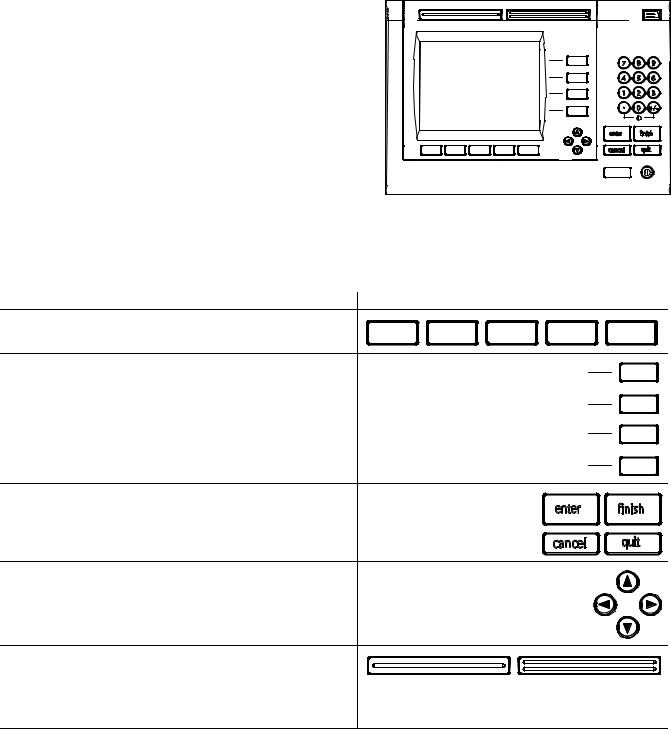
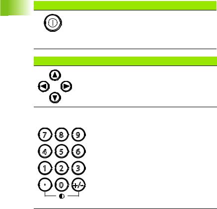
1LCD screen
2Soft keys
3Dimension keys
4Command keys
5Arrow cursor keys
6Numeric Keypad
7Fast track keys
8Send key
9LCD on/off key
7 |
|
|
|
8 |
|
|
|
3 |
|
|
|
|
|
|
7 |
8 |
9 |
1 |
|
6 |
4 |
5 |
6 |
|
|
|
1 |
2 |
3 |
|
|
4 |
|
0 |
+/- |
|
|
|
|
|
|
|
|
enter |
|
finish |
|
2 |
5 |
cancel |
|
quit |
|
|
|
|
|
||
|
|
|
|
|
9 |
ND 2100G panel keys
Panel keys are used to initiate feature measurements, apply tolerances, send reports of measurement results and configure operational parameters.
Panel function key |
Panel key |
Soft keys: Functions change in support of the activities displayed on the LCD.
Dimension keys: Can be assigned one of six hot key functions for use when DRO screen is displayed. When graph, bar value or data screens are displayed, dimension keys are used to display values for single dimensions or a smaller group of dimensions.
Command keys: Control measurement and data entry
processes. |
enter |
finish |
cancel quit
Arrow cursor keys: Used to scroll through lists and navigate menus and setup screen data fields.
Fast track keys: Two programmable fast track keys are used to perform frequently used functions. These keys can easily be located by touch without taking your eyes off the part. Users can program either fast track key as described later in the Hotkeys portion of Chapter 2: Installation, Setup and Specifications.
ND 2100G GAGE-CHEK |
3 |

Panel function key |
Panel key |
Numeric keypad: Used to enter numeric data. Additionally, the decimal point key and +/- key are used to adjust the contrast of the LCD display.
Send key: Used to transmit measurement results to a computer, USB printer or USB flash drive.
LCD On/Off key: Press the LCD on/off button to turn the LCD display off without removing power from the ND 2100G. Press the button a second time to restore the LCD display. Additionally, the LCD On/Off key can be used to clear channel calibrations, delete data stored for a single part or delete data stored for all parts.
7 
 8
8 
 9
9
4 
 5
5 
 6
6
1 
 2
2 
 3
3
0 
 +/-
+/-
4 |
Preface |
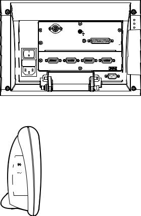
ND 2100G rear panel
1Power switch
2Power connection with fuse
3Ground (protective ground)
4Encoder inputs
5Relay outputs
6Parallel I/O port
7RS-232-C interface
ND 2100G side panel
1Speaker/headset jack
2USB Type A connector
3RJ-45 Foot switch/hand switch/keypad connector
15 |
3 |
|
|
|
16 |
1 |
14 |
|
|
2 |
7 |
|
1 
21 
3 

ND 2100G GAGE-CHEK |
5 |

Information contained in this manual
This User's manual covers the operation, installation, setup and specifications of the ND 2100G. Operating information is contained in chapter 1. Installation, setup instructions and specifications are contained in chapter 2.
Fonts used in this manual
The following fonts are used to indicate operator controls or to show emphasis:
Operator controls - soft keys and other panel keys are shown in upper case
Emphasis - Items of special interest or concepts that are emphasized to the user are shown in bold type
Showing sequences of key presses
The ND 2100G user performs sequences of soft key and panel key presses to measure part features and complete other tasks. These sequences are indicated using text as shown in the following example:
Press the MENU... soft key, press the DATUM... soft key and then press the MASTER soft key is sometimes abbreviated as:
Press MENU/DATUM/MASTER
Symbols within notes
Notes are marked with symbols on the left indicating the type, or potential severity of the information.
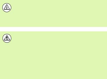
General Information
This is additional or supplementary information about an activity or concept.
Warning
This warns of a situation or condition that could lead to measurement errors, equipment malfunction or equipment damage. Do not proceed until the message is read and understood.
Caution - Risk of electric shock
This warns of a situation or condition that could lead to electrical shock and to personal injury or death. Do not proceed until the message is read and understood.
6 |
Preface |
Safety considerations
General accepted safety precautions must be followed when operating the system. Failure to observe these precautions could result in damage to the equipment, or injury to personnel. It is understood that safety rules within individual companies vary. If a conflict exists between the material contained in this manual and the rules of a company using this system, the more stringent rules should take precedence.
The ND 2100G is equipped with a 3-wire power plug that includes a separate ground connection. Always connect the power plug to a 3-wire grounded outlet. Use of 2-wire power plug adapters or any other connection accessories that remove the third grounded connection create a safety hazard and should not be permitted.
Unplug the ND 2100G from the power outlet and seek the assistance of a qualified service technician if:
The power cord is frayed or damaged or the power plug is damaged
Liquid is spilled or splashed onto the enclosure
The ND 2100G has been dropped or the exterior has been damaged
The ND 2100G exhibits degraded performance or indicates a need for service some other way
ND 2100G channel inputs
The ND 2100G can be connected to the following channel configurations.
1, 4, or 8 single input channels
Up to 16 networked RS-232 input channels
Or combinations of single input channels and networked RS-232 input channels for a total of up to 16 channels
Software version
The software version is shown in the About setup screen discussed later in chapter 2.
Cleaning
Use only a cloth dampened with water and a mild detergent for cleaning the exterior surfaces. Never use abrasive cleaners, and never use strong detergents or solvents. Only dampen the cloth, do not use a cleaning cloth that is dripping wet.
ND 2100G GAGE-CHEK |
7 |
8 |
Preface |
....1 Operation |
17 |
|
|
|
|
|
|
|
|
1.1 ND 2100G Overview .... |
18 |
|
|
|
|
|
|||
Overview .... 18 |
|
|
|
|
|
|
|
|
|
1.2 Basic operation of the ND 2100G |
.... 20 |
|
|
|
|
||||
Switching on the ND 2100G .... |
20 |
|
|
|
|
||||
Switching off the ND 2100G .... |
20 |
|
|
|
|
||||
1.3 Panel key descriptions |
21.... |
|
|
|
|
|
|||
Dimension keys |
.... |
|
23 |
|
|
|
|
|
|
1.4 LCD screens and menus 26.... |
|
|
|
|
|
||||
Screen navigation .... |
26 |
|
|
|
|
|
|||
Home screen .... |
27 |
|
|
|
|
|
|||
DRO screen .... |
27 |
|
|
|
|
|
|
||
View soft keys and screens .... |
28 |
|
|
|
|
||||
|
View soft keys for subgroups of one |
.... 28 |
|
|
|||||
|
Dimension graphs for SPC subgroups of one .... |
28 |
|
||||||
|
Dimension histograms for SPC subgroups of one .... |
29 |
|||||||
|
Bar and dial current value displays .... |
30 |
|
|
|||||
|
Dimension data tables for SPC subgroups of one .... |
31 |
|||||||
|
View soft keys for subgroups greater than one .... |
32 |
|||||||
|
Dimension |
|
charts for subgroups greater than one |
32 |
|||||
|
x |
||||||||
|
Dimension r charts for subgroups greater than one |
.... 33 |
|||||||
|
Dimension data tables for subgroups greater than one .... 34 |
||||||||
in/mm menu items |
35.... |
|
|
|
|
|
|||
Master menu items and screens .... |
35 |
|
|
|
|||||
|
Master screen for calibrating encoder datums .... |
35 |
|||||||
|
Master screen for calibrating transducer ranges .... |
|
36 |
||||||
Menu soft keys |
.... |
|
37 |
|
|
|
|
|
|
|
The datum menu functions .... |
37 |
|
|
|
||||
|
The Extra menu functions .... |
38 |
|
|
|
||||
|
Fast3 .... |
39 |
|
|
|
|
|
|
|
|
Setup menu functions .... |
40 |
|
|
|
|
|||
ND 2100G GAGE-CHEK |
9 |
1.5 Operating instructions .... |
41 |
|
|
|
|
|
Select a part to begin a measurement |
.... 42 |
|
|
|||
Establish a reference for the measurement |
.... 43 |
|
||||
Calibrating channels using the Master function .... 43 |
|
|||||
Calibration of a single reference point .... |
44 |
|
||||
Calibration groups (G1, G2, G3... |
G18) .... |
45 |
|
|
||
Calibrations of transducer resolution (Min-Max calibrations) .... |
46 |
|||||
Establishing a temporary dimension reference .... |
48 |
|
||||
Zeroing a dimension reference .... |
48 |
|
|
|||
Presetting a dimension reference to a specific value .... |
49 |
|||||
Clearing channel calibrations .... |
50 |
|
|
|
||
Clearing dimension references (presets) .... |
50 |
|
||||
Conducting measurements .... |
51 |
|
|
|
|
|
Manual measurements .... |
51 |
|
|
|
|
|
Sequential measurements .... 52 |
|
|
|
|||
Dynamically sampled measurements .... |
53 |
|
||||
Semi-automated measurements .... |
54 |
|
|
|||
Reviewing measurements .... 55 |
|
|
|
|
||
Printing reports or sending results to a computer .... 55 |
|
|||||
Printing reports |
.... 55 |
|
|
|
|
|
Sending data to a computer .... |
56 |
|
|
|
||
Data reports .... |
57 |
|
|
|
|
|
Clearing stored measurement data .... |
58 |
|
||||
10
....2 Installation, Setup, Formulas and Specifications |
59 |
|
||||||||
2.1 ND 2100G Shipment Contents .... |
60 |
|
|
|
|
|
||||
Items included with the ND 2100G .... |
60 |
|
|
|
|
|||||
Optional items possibly included |
.... 60 |
|
|
|
|
|||||
Repackaging the ND 2100G |
.... 61 |
|
|
|
|
|
||||
2.2 Hardware Installation .... |
62 |
|
|
|
|
|
|
|
||
Assembling the mounting stand .... |
62 |
|
|
|
|
|
||||
Benchtop location and mounting .... |
62 |
|
|
|
||||||
Arm mounting (optional) .... |
63 |
|
|
|
|
|
||||
Connecting power .... |
64 |
|
|
|
|
|
|
|
||
Connecting channel inputs .... |
65 |
|
|
|
|
|
|
|||
Connecting a computer |
.... 66 |
|
|
|
|
|
|
|||
Connecting headphones and USB printer .... |
66 |
|
|
|
||||||
Connecting headphones .... |
66 |
|
|
|
|
|
||||
Connecting a USB printer .... |
66 |
|
|
|
|
|||||
Connecting an optional foot switch or remote keypad .... |
67 |
|
||||||||
2.3 Software setup .... |
68 |
|
|
|
|
|
|
|
|
|
Setup menu .... |
69 |
|
|
|
|
|
|
|
|
|
Accessing and navigating the Setup menu .... |
70 |
|
|
|
||||||
Using dimension keys in the setup mode .... |
71 |
|
|
|||||||
Entering data into setup fields .... |
71 |
|
|
|
|
|
||||
Deleting data entries .... |
|
72 |
|
|
|
|
|
|
|
|
Entering setup parameters .... |
72 |
|
|
|
|
|
|
|||
Changing the channel or dimension number .... |
72 |
|
||||||||
Entering parameters .... |
73 |
|
|
|
|
|
||||
Copying parameters to other parts, dimensions or channels .... 73 |
||||||||||
Saving a parameter and advancing to the next .... |
74 |
|
||||||||
Saving a parameter and returning to the Setup menu .... |
74 |
|||||||||
Discarding changes and returning to the Setup menu .... |
74 |
|||||||||
Leaving the Setup menu .... |
75 |
|
|
|
|
|
|
|||
Printing ND 2100G setup configurations .... |
75 |
|
|
|
||||||
Saving or loading ND 2100G configurations |
.... 75 |
|
|
|
||||||
Minimum setup requirements .... |
76 |
|
|
|
|
|
||||
Setup screens .... |
76 |
|
|
|
|
|
|
|
|
|
About setup screen .... |
|
76 |
|
|
|
|
|
|
|
|
Dimensions setup screen .... |
77 |
|
|
|
|
|
|
|||
Creating part numbers .... |
77 |
|
|
|
|
|
||||
Selecting part numbers .... |
77 |
|
|
|
|
|
||||
Labeling parts and dimensions .... |
78 |
|
|
|
||||||
Defining visible and hidden dimensions .... |
78 |
|
|
|||||||
Copying dimension parameters to other parts .... |
79 |
|
||||||||
Deleting parts |
.... |
79 |
|
|
|
|
|
|
|
|
Formats setup screen .... |
80 |
|
|
|
|
|
|
|
||
Specifying a dimension .... |
80 |
|
|
|
|
|
||||
Specifying radius or diameter .... |
80 |
|
|
|
|
|||||
Display resolution .... |
81 |
|
|
|
|
|
|
|||
Formulas setup screen |
.... 82 |
|
|
|
|
|
|
|||
Variables setup screen .... |
83 |
|
|
|
|
|
|
|||
ND 2100G GAGE-CHEK |
11 |
Tolerances setup screen |
.... 84 |
|
|
|
|
|
|
||
|
Nominal values with tolerances .... |
|
85 |
|
|
|
|||
|
Nominal with +/- tolerances .... |
85 |
|
|
|
|
|
||
|
Nominal with ++ tolerances .... |
86 |
|
|
|
|
|
||
|
Nominal with -- tolerances .... |
87 |
|
|
|
|
|
||
|
Nominal with fixed limits .... |
88 |
|
|
|
|
|
||
|
Specifying an audio alert 89.... |
|
|
|
|
|
|||
|
Mirror values .... |
90 |
|
|
|
|
|
|
|
SPC setup screen |
|
|
|
|
|
|
|
||
|
Subgroup size .... |
91 |
|
|
|
|
|
|
|
|
Max subgroups .... |
91 |
|
|
|
|
|
|
|
|
Graph points .... |
92 |
|
|
|
|
|
|
|
|
Next record ID .... |
92 |
|
|
|
|
|
|
|
|
Dimension .... |
|
|
|
|
|
|
|
|
|
UCL and LCL .... |
93 |
|
|
|
|
|
|
|
|
|
|
93 |
|
|
|
|
|
|
|
x, r Ucl and Lcl .... |
|
|
|
|
|
|
||
|
Warning limits .... |
95 |
|
|
|
|
|
|
|
|
Showing and hiding SPC graphs .... |
|
95 |
|
|
|
|||
Header setup screen .... |
96 |
|
|
|
|
|
|
||
|
Labels 96.... |
|
|
|
|
|
|
|
|
|
Prompts .... |
|
|
|
|
|
|
|
|
Memory setup screen .... |
97 |
|
|
|
|
|
|
||
S labels setup screen .... |
97 |
|
|
|
|
|
|
||
S formulas setup screen |
.... 98 |
|
|
|
|
|
|
||
Globals setup screen .... |
98 |
|
|
|
|
|
|
||
Channels setup screen .... |
99 |
|
|
|
|
|
|
||
|
Specifying the input channel |
.... 99 |
|
|
|
|
|
||
|
Selecting the channel input type .... |
|
100 |
|
|
||||
|
Specifying input channel setup parameters .... |
|
101 |
||||||
|
Master link probe balancing .... |
101 |
|
|
|
|
|||
|
Setting the resolution for the linked channels .... |
|
102 |
||||||
|
Specifying channel input resolution |
.... 103 |
|
|
|||||
|
Specifying units of measure |
.... 104 |
|
|
|
||||
|
Reversing channel input polarity .... |
|
104 |
|
|
|
|||
|
Specifying encoder reference marks .... |
105 |
|
|
|||||
|
Changing the machine zero position .... |
106 |
|
|
|||||
|
Enabling scale error notification .... |
|
106 |
|
|
|
|||
|
Calibrating LVDT and HBT transducer gain .... |
106 |
|||||||
|
Centering (nulling) LVDT and HBT transducers |
.... 107 |
|||||||
|
Selecting an external RS-232 channel .... |
108 |
|
|
|||||
|
Specifying an RS-232 input port .... |
|
108 |
|
|
|
|||
|
EnDat 2.2 encoder interface |
.... 109 |
|
|
|
||||
Master setup screen .... |
111 |
|
|
|
|
|
|
||
|
Specifying the number of calibration points .... |
|
111 |
||||||
|
Selecting calibration type .... |
111 |
|
|
|
|
|
||
|
Locking the calibration process if warnings occur 112.... |
||||||||
|
Specifying a calibration interval .... |
112 |
|
|
|
||||
|
Using dynamic Min/Max values for calibration |
|
.... 113 |
||||||
|
Specifying Min and Max calibration warnings .... |
|
114 |
||||||
12
SLEC setup screen |
.... 115 |
|
|
|
|
||
SLEC or LEC, which is right for my application? .... 115 |
|||||||
LEC (Linear error correction) .... 115 |
|
||||||
SLEC (Segmented linear error correction) |
.... 116 |
||||||
SLEC setup procedure |
.... 118 |
|
|
|
|||
Clear all datums |
.... 118 |
|
|
|
|||
Cycle power & set machine zero |
.... 119 |
|
|||||
Clear old values & disable SLEC .... |
120 |
|
|||||
Enter machine zero offset |
.... 121 |
|
|||||
Enter new station values .... |
122 |
|
|
||||
Enable SLEC .... |
123 |
|
|
|
|
||
Display setup screen .... |
123 |
|
|
|
|
||
Radix for numeric displays |
.... 123 |
|
|||||
Display mode for angles .... |
123 |
|
|
||||
Startup angular and linear display modes .... |
124 |
||||||
Bar graph orientation .... |
125 |
|
|
||||
Bar graph or dial displays .... |
125 |
|
|
||||
Colors that indicate measurement results .... |
125 |
||||||
Units of measure .... 126 |
|
|
|
||||
Home screen .... |
126 |
|
|
|
|
||
Report setup screen .... |
127 |
|
|
|
|
||
Record number .... |
128 |
|
|
|
|||
Lines per page .... |
128 |
|
|
|
|||
Columns per page .... |
129 |
|
|
|
|||
Type of records to be printed .... |
129 |
|
|||||
Report characters setup screen .... |
130 |
|
|
||||
Send setup screen .... |
132 |
|
|
|
|
||
Auto Send Rec .... |
132 |
|
|
|
|||
Record Number .... |
132 |
|
|
|
|||
Record date, label and units of measure .... |
132 |
||||||
Record content .... |
133 |
|
|
|
|||
Min Dimen Size .... |
133 |
|
|
|
|||
Send characters setup screen .... |
134 |
|
|
||||
Parallel setup screen .... |
135 |
|
|
|
|
||
Remote control .... |
135 |
|
|
|
|||
I/O Debounce interval |
.... 135 |
|
|
||||
RS-232 setup screen .... |
136 |
|
|
|
|
||
Uart Id .... |
136 |
|
|
|
|
|
|
Baud rate .... |
136 |
|
|
|
|
||
Word length |
.... |
136 |
|
|
|
|
|
Stop bits |
.... |
137 |
|
|
|
|
|
Parity .... |
137 |
|
|
|
|
|
|
Handshaking .... |
137 |
|
|
|
|
||
End of character (EOC) delay .... |
137 |
|
|||||
Specifying end of line (EOL) delay .... 138 |
|
||||||
Serial port data type .... |
138 |
|
|
||||
ND 2100G GAGE-CHEK |
13 |
USB setup screen .... |
139 |
|
|
|
||
Data .... |
139 |
|
|
|
|
|
Destination .... |
139 |
|
|
|
||
File type .... 140 |
|
|
|
|
||
Current auto (file) number .... |
140 |
|
|
|||
Hot Keys setup screen .... |
141 |
|
|
|
||
Front panel keys for hot key mapping .... |
141 |
|
||||
Remote switches and parallel port pins for hot key mapping .... |
142 |
|||||
Assigning hot key functions .... |
143 |
|
|
|||
Clock setup screen .... |
152 |
|
|
|
||
Setting the date and time .... |
152 |
|
|
|||
Date format .... |
152 |
|
|
|
||
Time format .... |
153 |
|
|
|
||
External edge setup screen (optional) .... 154 |
|
|
||||
Edge input .... |
154 |
|
|
|
|
|
External edge probe timing .... |
154 |
|
|
|||
Edge Type .... |
155 |
|
|
|
|
|
Direction factor .... |
155 |
|
|
|
||
Teaching a probe diameter .... |
157 |
|
|
|||
Misc. setup screen .... |
158 |
|
|
|
||
Key delay .... |
158 |
|
|
|
|
|
Speaker volume .... |
158 |
|
|
|
||
Data entry message time .... |
158 |
|
|
|||
Switch view .... |
159 |
|
|
|
||
Cpk/Ppk display .... |
159 |
|
|
|
||
Slew limit .... |
159 |
|
|
|
|
|
Start Scr saver .... |
159 |
|
|
|
||
Scr Saver Off |
.... 160 |
|
|
|
||
Startup hold .... |
160 |
|
|
|
||
Strict Unit Check .... |
160 |
|
|
|
||
Supervisor setup screen .... |
161 |
|
|
|
||
Password .... |
161 |
|
|
|
|
|
Unlocking and locking critical functions .... |
161 |
|
||||
14
2.4 Formulas .... 163 |
|
|
|
|
|
|
|
|
|
Introduction to formulas .... |
|
163 |
|
|
|
||||
How do formulas relate inputs to dimensions? .... |
165 |
||||||||
Visible or hidden dimensions? |
.... 165 |
|
|
||||||
Visible dimensions .... |
|
165 |
|
|
|
||||
Hidden dimensions .... |
|
165 |
|
|
|
||||
When are dimensions stored in the ND 2100G database? .... 166 |
|||||||||
What can formulas do? .... |
166 |
|
|
||||||
When are formulas constructed or edited? .... |
167 |
|
|||||||
How can formulas be recorded for safekeeping? .... |
167 |
||||||||
Constructing and editing formulas .... |
168 |
|
|
||||||
Formula setup screen .... |
168 |
|
|
|
|||||
Formula construction example |
.... 171 |
|
|
||||||
Long formulas |
.... 175 |
|
|
|
|
||||
Deleting formula elements .... |
175 |
|
|
||||||
Formula functions .... |
|
176 |
|
|
|
|
|
|
|
Basic and advanced formula functions .... 177 |
|
||||||||
Basic formula functions .... |
178 |
|
|
|
|
||||
Channel functions .... |
|
179 |
|
|
|
||||
Dimension functions |
.... |
181 |
|
|
|
||||
Arithmetic operators |
.... |
183 |
|
|
|
||||
Units of measure .... |
|
184 |
|
|
|
||||
Basic math functions .... |
185 |
|
|
|
|||||
Exponent function (exp) |
.... 186 |
|
|
||||||
Trig and inverse trig functions (sin through atan) .... |
187 |
||||||||
Absolute value (abs) function .... |
188 |
|
|
||||||
Integer function (int) |
.... 189 |
|
|
|
|||||
Pi and other constants .... |
190 |
|
|
|
|||||
Advanced formula functions .... |
191 |
|
|
|
|||||
Commas (,) .... |
|
194 |
|
|
|
|
|
|
|
Semicolon (;) .... |
195 |
|
|
|
|
|
|||
Logical and control .... |
|
196 |
|
|
|
||||
Din .... |
198 |
|
|
|
|
|
|
|
|
Dout .... |
198 |
|
|
|
|
|
|
|
|
MinIndex and MaxIndex |
.... 199 |
|
|
||||||
RsetDyn .... |
199 |
|
|
|
|
|
|
||
If function .... |
200 |
|
|
|
|
|
|
||
Case function .... |
201 |
|
|
|
|
||||
Minimum (min) and maximum (max) functions .... |
204 |
||||||||
Average (avg) and median (md) functions .... |
206 |
|
|||||||
Modulo (mod) function .... |
207 |
|
|
|
|||||
Sequence (seq) function |
.... 208 |
|
|
||||||
Trip function and measurement automation .... |
212 |
||||||||
Dynamic minimum (Dmn) and dynamic maximum (Dmx) functions .... 215 |
|||||||||
Dynamic average (Davg) and dynamic median (Dmd) functions .... 217 |
|||||||||
Fail function |
.... |
218 |
|
|
|
|
|
|
|
ND 2100G GAGE-CHEK |
15 |
Xtra menu functions .... |
219 |
|
|
|
|
||||
Ask function .... |
222 |
|
|
|
|
||||
Beep function .... |
|
223 |
|
|
|
|
|||
Clear all data function .... |
224 |
|
|
||||||
Clear data function .... |
224 |
|
|
|
|||||
ClrTrig, SetTrig and user defined events .... |
225 |
||||||||
OnEvent function .... |
226 |
|
|
|
|
||||
DateStr function .... |
|
228 |
|
|
|
|
|||
TimeStr function .... |
|
228 |
|
|
|
|
|||
Time function .... |
|
229 |
|
|
|
|
|||
Din and DinBin function .... |
|
230 |
|
|
|||||
Din .... |
230 |
|
|
|
|
|
|
|
|
DinBin |
.... 232 |
|
|
|
|
|
|
|
|
Dout and DoutBin function |
.... 233 |
|
|
||||||
Dout .... |
233 |
|
|
|
|
|
|
|
|
DoutBin .... |
235 |
|
|
|
|
|
|
|
|
Display function |
.... |
|
237 |
|
|
|
|
||
FnDefine, FnParam and FnCall functions .... |
238 |
||||||||
Variable and Global functions .... 240 |
|
||||||||
Variables .... |
240 |
|
|
|
|
|
|
||
Globals .... |
242 |
|
|
|
|
|
|
|
|
Loop function .... |
|
243 |
|
|
|
|
|||
Remark function .... |
|
244 |
|
|
|
|
|||
HwDmn and HwDmx functions .... |
245 |
|
|||||||
RsetDyn function |
.... |
245 |
|
|
|
|
|||
HwLx function .... |
|
246 |
|
|
|
|
|||
Lookup and data lookup .... |
|
247 |
|
|
|||||
Master function |
.... |
|
250 |
|
|
|
|
||
MaxIndex and MinIndex functions |
.... 251 |
|
|||||||
PartNo function .... |
|
|
252 |
|
|
|
|
||
Preset function .... |
|
253 |
|
|
|
|
|||
Recall function .... |
|
254 |
|
|
|
|
|||
Relay function .... |
|
255 |
|
|
|
|
|||
Report function .... |
|
257 |
|
|
|
|
|||
Scan function .... |
|
258 |
|
|
|
|
|||
Send function .... |
|
263 |
|
|
|
|
|||
SendMsg function .... |
264 |
|
|
|
|||||
SendRec function .... |
265 |
|
|
|
|
||||
SetColor function |
.... |
266 |
|
|
|
|
|||
Setup function .... |
|
267 |
|
|
|
|
|||
Xlatch function .... |
|
268 |
|
|
|
|
|||
2.5 Specifications .... |
270 |
|
|
|
|
|
|
|
|
Dimensions .... |
272 |
|
|
|
|
|
|
|
|
Arm mount bracket |
.... 273 |
|
|
|
|||||
16

Operation
1.1 ND 2100G Overview
1.1 ND 2100G Overview
Overview
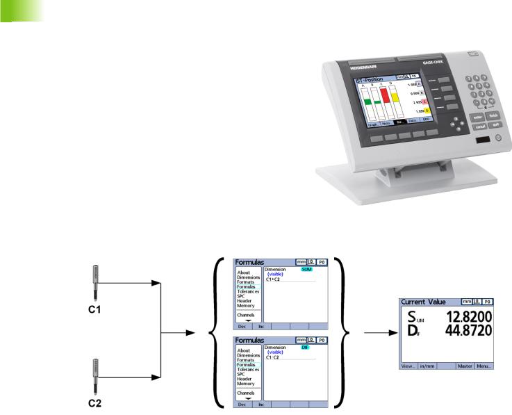
The ND 2100G is an advanced digital readout system for performing single or multiple gage measurements at very high levels of precision and accuracy. Dimensional inspections of components are performed using encoders or transducers as part of in-line production activities, or final quality inspection. Measurements are conducted under operator control, or are semi-automated and conducted in conjunction with a fixtured gage system.
The ND 2100G is configured at the factory to support
One, four or eight single-input channels, or
Up to 16 multiplexed RS-232 input channels, or
Combinations of single-input channels and multiplexed RS-232 input channels for a total of up to 16 channels
Channel inputs can be algebraically combined or processed by powerful math and control formulas to display dimensions such as flatness, volume and runout. Formulas are created as part of the ND 2100G setup using straightforward screen control and math functions.
C1=28.846 mm |
Sum=C1+C2 |
Sum=12.820 |
C2=-16.026 mm |
Dif=C1-C2 |
Dif=44.872 |
Channel inputs are processed by formulas to display dimensions.
18 |
1 Operation |

The intuitive user interface includes a large character color LCD for fast and accurate measurement feedback. User interface screens include a digital readout of current values, bar and dial position value indicators, graphs of values, histograms of measurement statistics and tables of measurement and of SPC data.
Digital readout (DRO) |
Horizontal bar |
Vertical bar |
Dial |
Graph of values |
Histogram of values |
Measurement data |
SPC data |
1.1 ND 2100G Overview
ND 2100G GAGE-CHEK |
19 |

1.2 Basic operation of the ND 2100G
1.2Basic operation of the ND 2100G
Switching on the ND 2100G
Switch on the ND 2100G. The POWER switch is located on the rear of the enclosure. After switching the power on, or after a power failure, the power-up screen will be displayed.
|
Press the FINISH key to advance from the power-up |
finish |
screen to the home screen. |
|
Your ND 2100G is now ready for operation.
Power-up screen.
Switching off the ND 2100G
Switch the ND 2100G off. The parts, formulas and dimensions that have been saved during operation will be retained in memory.
20 |
1 Operation |
1.3 |
Panel key descriptions |
|
|
|
descriptions |
||
|
|
|
|
||||
Descriptions of panel key functions are provided in the following |
|
|
|
|
|||
pages for Command, Fast Track, Send, LCD On/Off and Arrow Cursor |
|
|
|
|
|||
keys. Soft key functions are also described later as part of LCD |
|
|
|
|
|||
screens and menus. |
|
|
|
|
|
||
Command keys |
Function |
7 |
8 |
9 |
|
||
4 |
5 |
6 |
|
||||
|
|
Enter data: Press the ENTER key to enter |
|
||||
enter |
1 |
2 |
3 |
key |
|||
LCD is stored as measurement or |
|||||||
|
|
|
|||||
|
|
data for a measurement. Information on the |
|
0 |
+/- |
|
|
|
|
configuration data. This information includes |
enter |
finish |
Panel |
||
|
|
|
|
|
|||
|
|
current dimension values or alphanumeric |
cancel |
|
quit |
||
|
|
data for a configuration or user prompt data |
|
|
|
|
|
|
|
field. |
|
|
|
|
|
|
|
Exit a screen: Press the FINISH key to exit a |
ND 2100G Panel keys. |
|
|
1.3 |
|
finish |
screen saving any changes that were made. |
|
|
|
|||
The FINISH key may also be used to return |
|
|
|
|
|||
|
|
|
|
|
|
||
|
|
from the display of measurement or SPC data |
|
|
|
|
|
|
|
to the current home screen. |
|
|
|
|
|
cancel
Delete data or features: Press the CANCEL key to erase the last data value entered into the system from the numeric keypad or delete data in configuration fields.
quit
Quit current activity: Press the QUIT key to abort the current task and return to the home screen or to exit the current menu.
Fast Track keys |
Function |
|
Left frequently used function: |
|
Press the LEFT WIDE key to initiate |
|
the function programmed for this |
|
key. The factory default function for |
|
this key is RSETDYN. |
|
Right frequently used function: |
|
Press the RIGHT WIDE key to |
|
initiate the function programmed for |
|
this key. The factory default function |
|
for this key is ENTER. |
Send key |
Function |
|
Transmit measurement results: Press the |
|
SEND key to transmit measurement data to a |
|
computer, a USB printer or a USB memory |
|
drive. |
ND 2100G GAGE-CHEK |
21 |
1.3 Panel key descriptions
LCD On/Off key |
Function |
|
Turn the LCD off or clear data: Press the |
|
LCD ON/OFF key to toggle between LCD on |
|
and LCD off, or to clear channel calibrations, |
|
delete data stored for a single part or delete |
|
data stored for all parts |
Arrow cursor keys |
Function |
|
Navigate menus and setup screen |
|
data fields. |
Numeric keys |
Function |
7 
 8
8 
 9
9
4 
 5
5 
 6
6
1 
 2
2 
 3
3
0 
 +/-
+/-
The numeric keypad is used primarily for numeric data entry. The decimal point key and +/- key can also be used to increase or decrease the LCD screen contrast when a decimal point or +/- input are not expected by the system as part of a data entry process. The screen contrast setting will be saved when the system is powered down and used as the default contrast setting the next time the system is turned on.
22 |
1 Operation |
Dimension keys
Dimension keys can be assigned one of six hot key functions for use when the DRO screen is displayed. When graph, bar value and data screens are displayed, the dimension keys are used to display values for single dimensions or a smaller group of dimensions.
Dimension keys |
Function |
|
Pressing a dimension key in the: |
|
DRO screen: performs the function |
|
assigned in the hotkey setup |
|
screen. By default no hotkey |
|
function is assigned until the user |
|
makes the assignment |
|
Graph screens: displays a single |
|
graph for the corresponding |
|
dimension |
|
Bar screens: Displays a single bar |
|
showing current values for the |
|
corresponding dimension |
|
Data screens: displays a single data |
|
table of stored values for the |
|
corresponding dimension |
Hot key assignments are discussed in detail on page 141.
Soft keys Function
Soft keys initiate functions that are labeled above the keys at the bottom of the LCD screen. As different system functions are selected, the soft key labels change in support of those functions.
Pressing the dimension A key in a graph screen selects the A graph for display.
1.3 Panel key descriptions
ND 2100G GAGE-CHEK |
23 |
1.3 Panel key descriptions
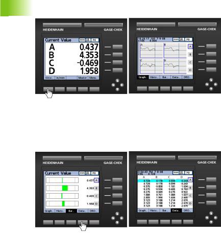
Pressing the VIEW... soft key changes soft key labels to show five screen viewing options, graph, histogram, bar, data and DRO.
Pressing the VIEW... soft key causes soft key labels to change, offering five options for viewing data.
When viewing graphs of stored data, current value bars or tables of stored data, pressing a different soft key changes to the view indicated by the soft key label.
Pressing the DATA... soft key when viewing bars causes the dimension data table to be displayed.
24 |
1 Operation |
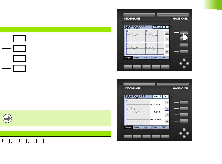
Pressing the currently highlighted soft key alternates between singledimension and multiple-dimensions displays.
Pressing the BAR... soft key when viewing multiple-dimensions causes the currently selected dimension to be displayed by itself.
The left most soft keys can be designated hotkeys to provide quick access to commonly used functions when the home screen is displayed. Hot key assignments are discussed in detail in Chapter 2: Installation, Setup and Specifications.
1.3 Panel key descriptions
ND 2100G GAGE-CHEK |
25 |
1.4 LCD screens and menus
1.4 LCD screens and menus
The ND 2100G LCD presents a variety of screens and menus selected by the user to display current dimension values, pass fail test results, dimension value graphs, statistical process control graphs and data tables, and setup and part configuration options.
Screen navigation
ND 2100G screen navigation is straightforward. For example, to display a bar graph of current values from the home screen, press the MENU... soft key, then press the VIEW... soft key and then the BAR...
soft key.
Press the VIEW... soft key then the BAR... soft key.
26 |
1 Operation |
Home screen
The home screen is displayed after the startup screen when power is applied to the ND 2100G, and is displayed after the FINISH key is pressed to complete a measurement or screen evaluation.The default home screen is the DRO, but can be reassigned to another screen in the Display setup screen.
The assignment of the home screen is discussed in detail in Chapter 2: Installation, Setup and Specifications.
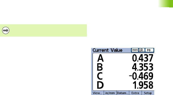
DRO screen
The DRO screen is the default home screen displayed after power is applied and the startup screen is shown.The DRO screen provides numeric displays of the current values of up to four dimensions. The unit of measure, current datum and current part number or part name are displayed in the upper right corner of the screen.
Use the arrow cursor keys to scroll dimensions when more than four dimensions are active.
DRO screen
1.4 LCD screens and menus
ND 2100G GAGE-CHEK |
27 |
1.4 LCD screens and menus
View soft keys and screens
View soft keys for subgroups of one
Pressing the VIEW... soft key when using subgroups of one, changes soft key labels to show five screen viewing options. Graph, histogram, bar, data and DRO.
View soft keys |
Function |
GRAPH... |
Displays data in a line graph |
|
|
HISTO... |
Displays data in a histogram |
|
|
BAR... |
Displays data in a bar graph |
|
|
DATA... |
Displays numerical data |
|
|
DRO... |
Displays the DRO screen |
|
|
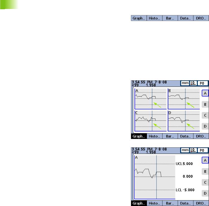
Dimension graphs for SPC subgroups of one
The dimension graph screen is displayed for SPC subgroups of 1, and displays graphs for up to 16 dimensions.
Press the GRAPH... soft key to change the number of graphs presented on the screen. Press a dimension soft key to display a graph of the dimension and the minimum additional dimensions. Use the arrow cursor keys to scroll the graphs when more data is stored than will fit on the screen.
Individual samples are selected by a vertical line on the graph. Move the vertical line left and right through the stored data using the arrow cursor keys. The time and date that the selected sample was stored are shown in the upper left corner of the screen. The ID number of the sample for the dimension and the value of the data are also shown in the upper left corner. Displays of a single dimension also show the nominal and control limit values.
View soft keys for subgroups of one.
Vertical selection lines.
Dimension line graphs for subgroups of one.
28 |
1 Operation |

Dimension histograms for SPC subgroups of one
The dimension histogram screen displays histograms of values for up to 16 dimensions. The dimension histogram screens are displayed for SPC subgroups of one.
Press the HISTO... soft key to change the number of histograms presented on the screen. Press a dimension soft key to display the histogram of a single dimension.
The display of a single dimension also shows the total range and mean of the values.
Dimension histograms for subgroups of one.
1.4 LCD screens and menus
ND 2100G GAGE-CHEK |
29 |
1.4 LCD screens and menus
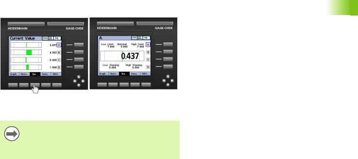
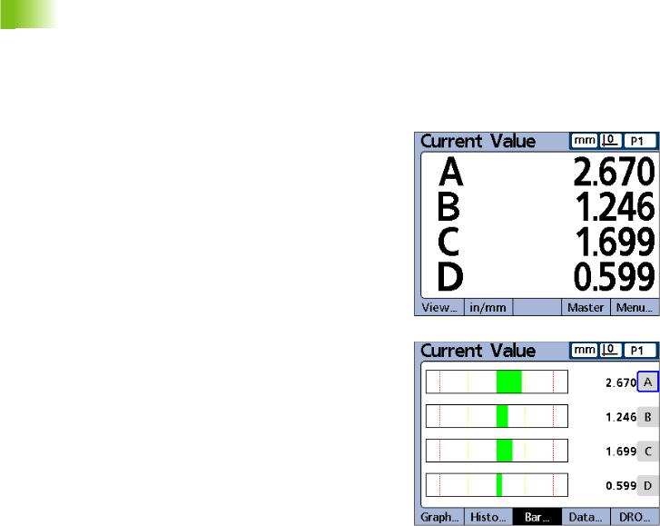
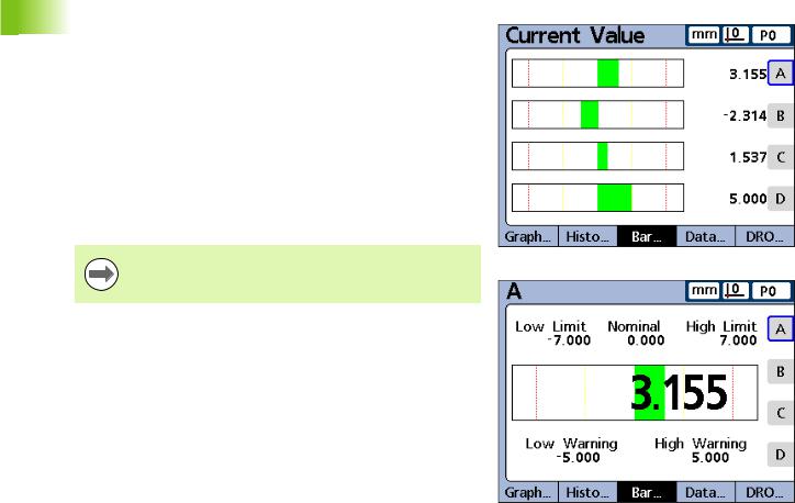
Bar and dial current value displays
The bar and dial screens provide graphic displays of the current values of up to 16 dimensions. The default bar screen can be configured to display current value bars in horizontal or vertical orientation using the Display setup screen.
Bar displays of multiple dimensions show current values. Bar displays of single dimensions include the current value, nominal value, and high and low warning and limit values.
Press the BAR... soft key to change the number of bars presented on the screen. Press a dimension soft key to display a bar for a single dimension.
The display can be configured in the Display setup screen to include a dial in addition to the bars. When the dial display is also available, press the BAR... soft key to toggle between the bars and the dial.
The display of a single dimension can be configured to be a bar or a dial, but cannot be toggled between a single bar and a single dial.
Bar graphs for subgroups of one.
30 |
1 Operation |
Loading...