


ND 920
Position Display Units
for Milling Machines
User´s Manual
11/ 95
inch
REF
R+
PGM
R–
0
CL
HOLD
POS
MOD
ENT
R
+
-
SPEC
FCT
PGM
GOTO
X
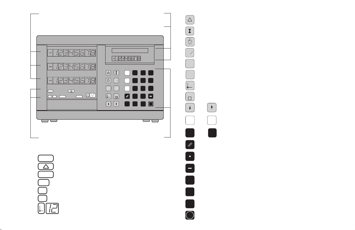
Position display
(ND 920: only two axes)
HEIDENHAIN
HOLD
POS
GOTO
PGM
SPEC
FCT
X
Z
0
1
2
3
4
5
6
7
8
9
CL
MOD
.
Y
R
+
-
REF
PGM
R- inch
R
+
ENT
Distance-to-go display is active
Clear entry/cancel operating mode
Hold current position/output measured values
Select/deselect parameter list,
activate RS-232-C
Confirm entry
Inch display is active
Program input is active
Radius compensation R+ is active
Radius compensation R– is active
Datum point number
Message field
Input field
Status
display:
Keyboard (ND 920 has no Z key)
9
Distance-to-go display (traversing to zero)
For incremental dimensions (only with
distance-to-go and program input)
Tool compensation
Call radius compensation for the current tool
Special functions (probing functions,
hole patterns, rectangular pocket)
Program input
Select datum
Go directly to parameters or program steps
Page in program or parameter list/
Select coordinate axis
Numerical input
Reset all axes to zero,
functions for Program Input
Decimal point
Change sign or parameter
Z
•••
•••
select function
Reference marks have been crossed

Part I: Operating Instructions
Part I: Operating Instructions
Fundamentals 4
Switch-On, Crossing Over the Reference Marks 9
Switching Between Operating Modes 9
Datum Setting 10
Datum setting with the tool 11
Datum setting with the KT Edge Finder 13
Resetting all axes to zero 18
Holding Positions 19
Tool Compensation 21
Moving the Axes with Distance-To-Go 22
Bolt Hole Circles and Bolt Circle Segments 24
Linear Hole Patterns 27
Rectangular Pocket 30
Scaling Factors 33
Program Input 34
Program Output over RS-232-C Interface 37
Error Messages 38
Part II: Installation and Specifications 39
3
About this manual
This manual is divided into two parts:
Part I: Operating Instructions
• Fundamentals of positioning
• ND functions
Part II: Installation and Specifications
• Mounting the display unit on the machine
• Description of operating parameters
• Switching inputs, switching outputs
This manual is for ND display units with the
following software numbers or higher:
ND 920 (2 axes) 246 112 05
ND 960 (3 axes) 246 112 05
NDP 960 (3 axes, panel mount) 246 112 05
4
Y
X
Z
+Y
+X
+Z
–Z
–Y
–X
Datum or
origin
Graduation
Fundamentals
You can skip this chapter if you are already familiar with
coordinate systems, incremental and absolute dimensions,
nominal positions, actual positions and distance-to-go.
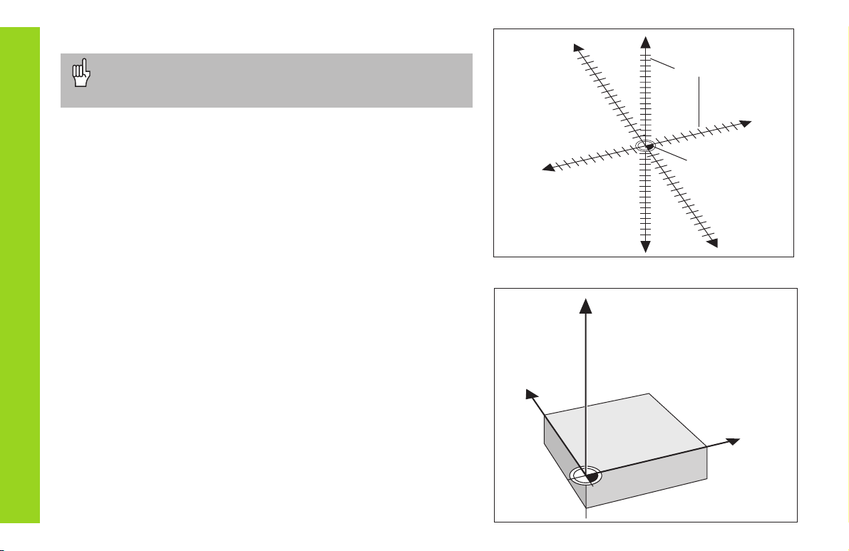
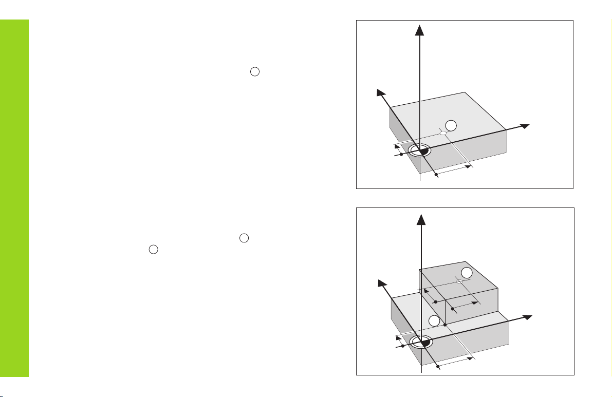
Coordinate system
To describe the geometry of a workpiece, the
Cartesian*
coordinate
system is used. The Cartesian coordinate system consists of three
mutually perpendicular axes X, Y and Z. The point of intersection of
these axes is called the datum or origin of the coordinate system.
Think of the axes as scales with divisions (usually in millimeters) which
allow us to fix points in space referenced to the datum.
To determine positions on a workpiece, the coordinate system is “laid”
onto the workpiece.
The machine axes are parallel to the axes of the coordinate system.
The Z axis is normally the tool axis.
*) Named in honor of the French mathematician and philosopher
René Descartes (1596 to 1650)
Fundamentals
5
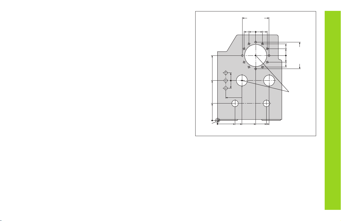
Datum setting
The workpiece drawing is used as the basis for machining the
workpiece. To enable the dimensions in the drawing to be converted
into traverse distances of machine axes X, Y and Z, each drawing
dimension requires a datum or reference point on the workpiece (since
a position can only be defined in relationship to another position).
The workpiece drawing always indicates one absolute datum (the
datum for absolute dimensions). However, it may contain additional
relative datums.
In the context of a numerical position display unit,
datum setting
means
bringing the workpiece and the tool into a defined position in relation to
each other and then setting the axis displays to the value which
corresponds to that position. This establishes a fixed relationship
between the actual positions of the axes and the displayed positions.
You can set up to 99 absolute datum points and store them in
nonvolatile memory.
0
325
450
700
900
950
0
320
750
1225
300±0,1
0
150
-150
0
0
216,5
250
-250
-125
-216,5
0
-125
-216,5
-250
250
125
216,5
125
Fundamentals
Absolute
datum
Relative
datums
6
Absolute workpiece positions
Each position on the workpiece is uniquely defined by its absolute
coordinates.
Example Absolute coordinates of position
1
:
X = 10 mm
Y = 5 mm
Z = 0 mm
If you are working according to a workpiece drawing with absolute
dimensions, you are moving the tool to the coordinates.
Y
X
Z
10
5
1
1
Y
X
Z
10
5
10
10
1
2
1
Relative workpiece positions
A position can also be defined relative to the previous nominal position.
The datum for the dimension is then located at the previous nominal
position. Such coordinates are termed incremental coordinates or
chain dimensions. Incremental coordinates are indicated by a preceding
I.
Example Relative coordinate of position referenced to
position :
IX = 10 mm
IY = 10 mm
If you are working according to a workpiece drawing with incremental
dimensions, you are moving the tool by the dimensions.
Sign for incremental dimensioning
A relative dimension has a positive sign when the axis is moved in the
positive direction, and a negative sign when it is moved in the negative
direction.
Fundamentals
2
7
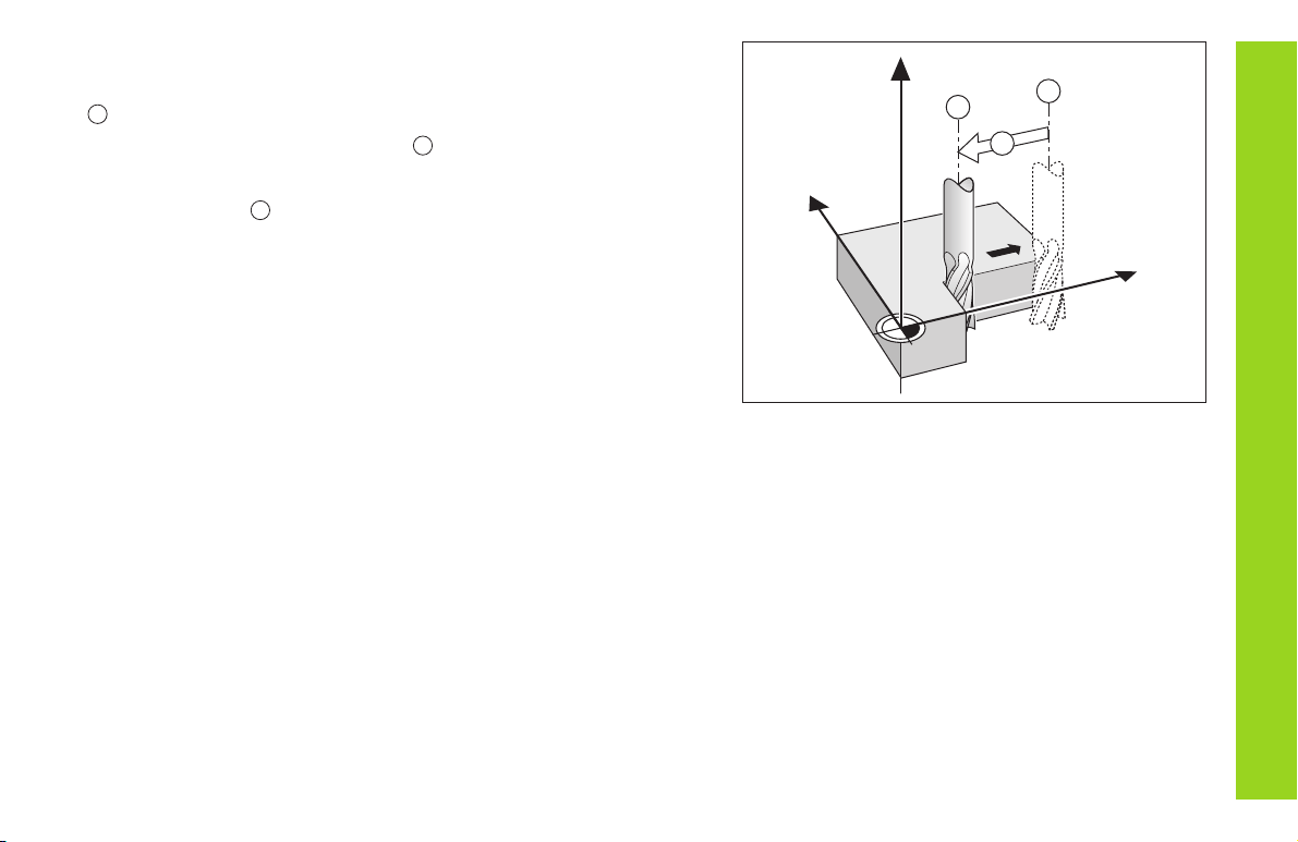
Nominal position, actual position and distance-to-go
The position to which the tool is to move is called the nominal position
(
S
). The position at which the tool is actually located at any given
moment is called the actual position (
I
).
The distance from the nominal position to the actual position is called
the distance-to-go (
R
).
Sign for distance-to-go
When you are using the distance-to-go display, the nominal position
becomes the relative datum (display value 0). The distance-to-go is
therefore negative when you move in the positive axis direction, and
positive when you move in the negative axis direction.
Fundamentals
Y
X
Z
I
S
R
8
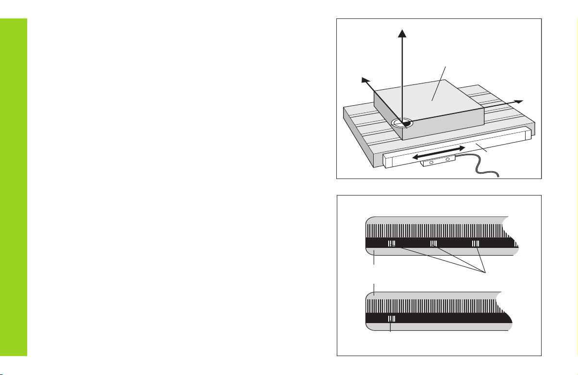
Position encoders
The position encoders on the machine convert the movements of the
machine axes into electrical signals. The ND display unit evaluates
these signals, determines the actual position of the machine axes and
displays the position as a numerical value.
If the power is interrupted, the relationship between the machine axis
positions and the calculated actual positions is lost. The reference
marks on the position encoders and the REF reference mark evaluation
feature enable the ND to quickly re-establish this relationship again
when the power is restored.
Reference marks
The scales of the position encoders contain one or more reference
marks. When a reference mark is crossed over, a signal is generated
which identifies that position as a reference point (scale datum =
machine datum).
When this reference mark is crossed over, the ND's reference mark
evaluation feature (REF) restores the relationship between axis slide
positions and display values which you last defined by setting the
datum. If the linear encoders have distance-coded reference marks,
you only need to move the machine axes a maximum of 20 mm to do
this.
Y
X
Z
Workpiece
Scale in Distance-coded
linear encoder reference marks
Reference mark
Position
encoder
Fundamentals
9
Switch-On, Crossing Over the Reference Marks
REF ? ENT ...CL
PASS OVER REF.
Turn on power (switch located on rear panel).
REF and decimal points in status display blink.
Press ENT before crossing reference marks
Cross over the reference marks in all axes (in any
sequence). Each axis display becomes active
when its reference mark is crossed over.
0
➨➨
➨➨
➨ 1
ENT
Crossing over the reference marks stores the last relationship between
axis slide positions and display values for all datum points (99 per axis)
in nonvolatile memory.
Note that if you choose
not
to cross over the reference marks (by
clearing the dialog REF ? with the CL key), this relationship will be
lost if the power is interrupted or when the unit is switched off.
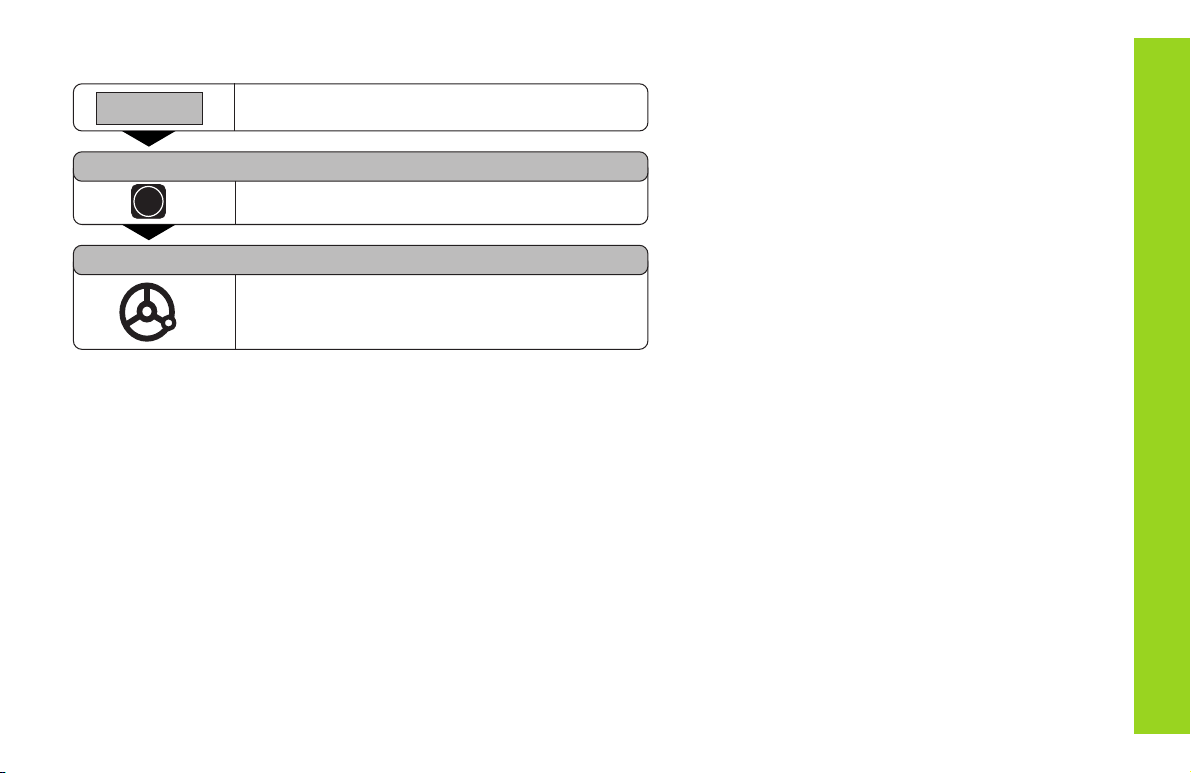
Switching Between Operating Modes
You can switch between the operating modes
Distance-To-Go, Special Functions, Program Input,
Set Tool Datum, Hold Position and Parameter Input at
any time simply by pressing another operating mode
key.
Switch-On, Crossing Over the Reference Marks
10
Datum Setting
If you want to save the datum points in nonvolatile memory,
you must first cross over the reference marks.
Only after crossing over the reference marks can you set new datums
or activate existing ones.
Probe the workpiece with the edge finder and then set the desired
datum. You can also probe two edges and set the centerline between
them as a datum (see examples), or probe four points on a circle and
set the circle center as the datum. The display unit will automatically
consider the stylus radius and length if their values are entered in
parameters P25 and P26 (see “Operating Parameters”).
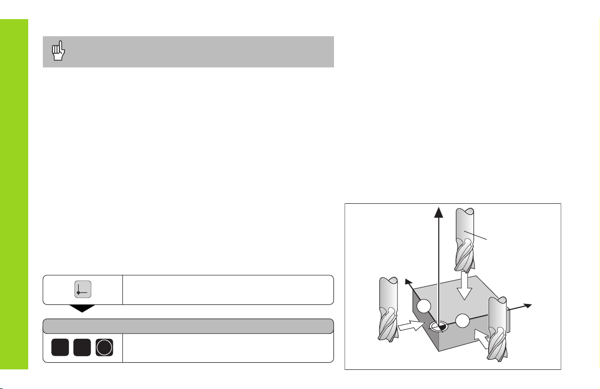
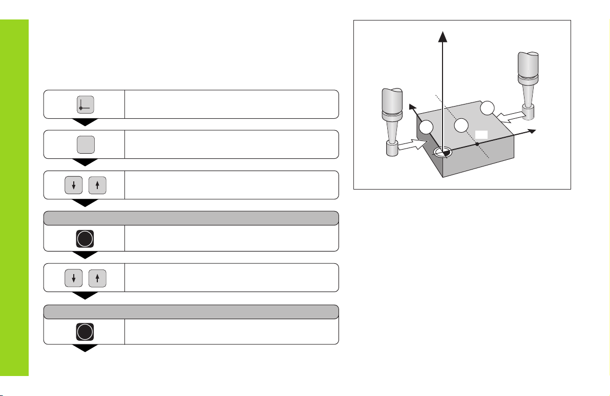
There are several ways to set datums:
Touch the workpiece with the tool and then set the desired datum
(see example). You can also touch two edges and set the centerline
between them as a datum, or touch four points on a circle and set the
circle center as the datum. The tool data of the tool used for this are
automatically considered (see “Tool Compensation”).
DATUM NUMBER =
After you have set a datum it can be activated as follows:
1
Select datum setting.
Enter the number of the datum point, for
example 12.
2
ENT
Datum Setting
Y
X
2
1
Z
R = 5 mm
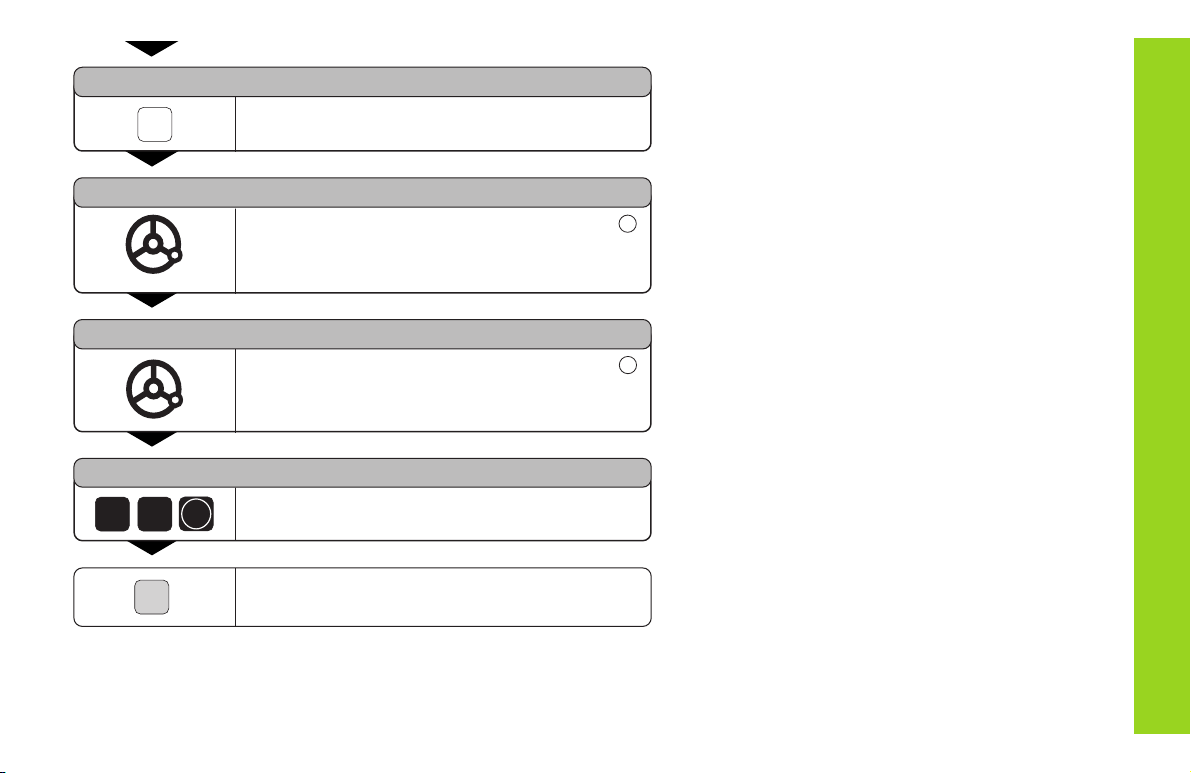
Datum setting with the tool
Example
Working plane X / Y
Tool axis Z
Tool radius R = 5 mm
Axis sequence for X – Y – Z
datum setting

11
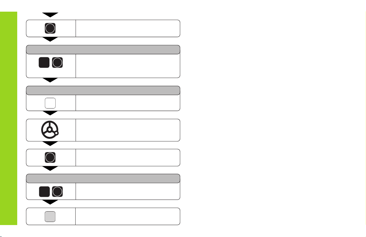
Datum Setting
Select the datum point number.
Select special functions.
SPEC
FCT
Select PROBING FUNCTION.
PROBING FUNCTION ?
ENT
Confirm selection.
Select PROBE EDGE.
PROBE EDGE ?
ENT
Confirm selection.
•
•
•
PROBE X
X
Select the X axis (if not already selected).
Touch workpiece edge .
ENT
The X position is captured.
POS. MEASURED X =
Enter the position value for the datum.
Tool radius compensation is automati-
cally accounted for.
0
PROBE X
Y
Select the X axis.
Touch workpiece edge .
1
•
•
•
2
ENT
12
Datum Setting
ENT
The Y position is captured.
POS. MEASURED Y =
Enter the position value for the datum in
the Y axis. Tool radius compensation is
automatically considered.
0
PROBE Y
Z
Select the Z axis.
Touch the workpiece with the tool.
ENT
The Z position is captured.
POS. MEASURED Z =
Enter the position value for the datum
in the Z axis.
SPEC
FCT
When you have set the datum, leave
the probing function.
ENT
0
ENT

13
Datum Setting
Datum setting with the KT edge finder
Your display unit offers the following probing functions:
PROBE EDGE Set workpiece edge as datum
PROBE MIDPOINT Set centerline between two workpiece edges
as datum
PROBE CIRCLE Set a circle center as datum
The probing functions can be accessed in operating mode SPEC FCT.
The HEIDENHAIN KT 120 edge finder only functions with
electrically conductive workpieces.
Before you can use the edge finder you must enter the stylus diameter
in parameter P25 and the stylus length in P26 (see “Operating Para-
meters”).
The stylus dimensions you enter are considered during all probing
operations.
PROBE EDGE and PROBE MIDPOINT are described on the following
pages.
The sequence for PROBE CIRCLE is similar; however, you must probe
four points before the circle center can be calculated. The circle center
can then be set as the new datum.
14
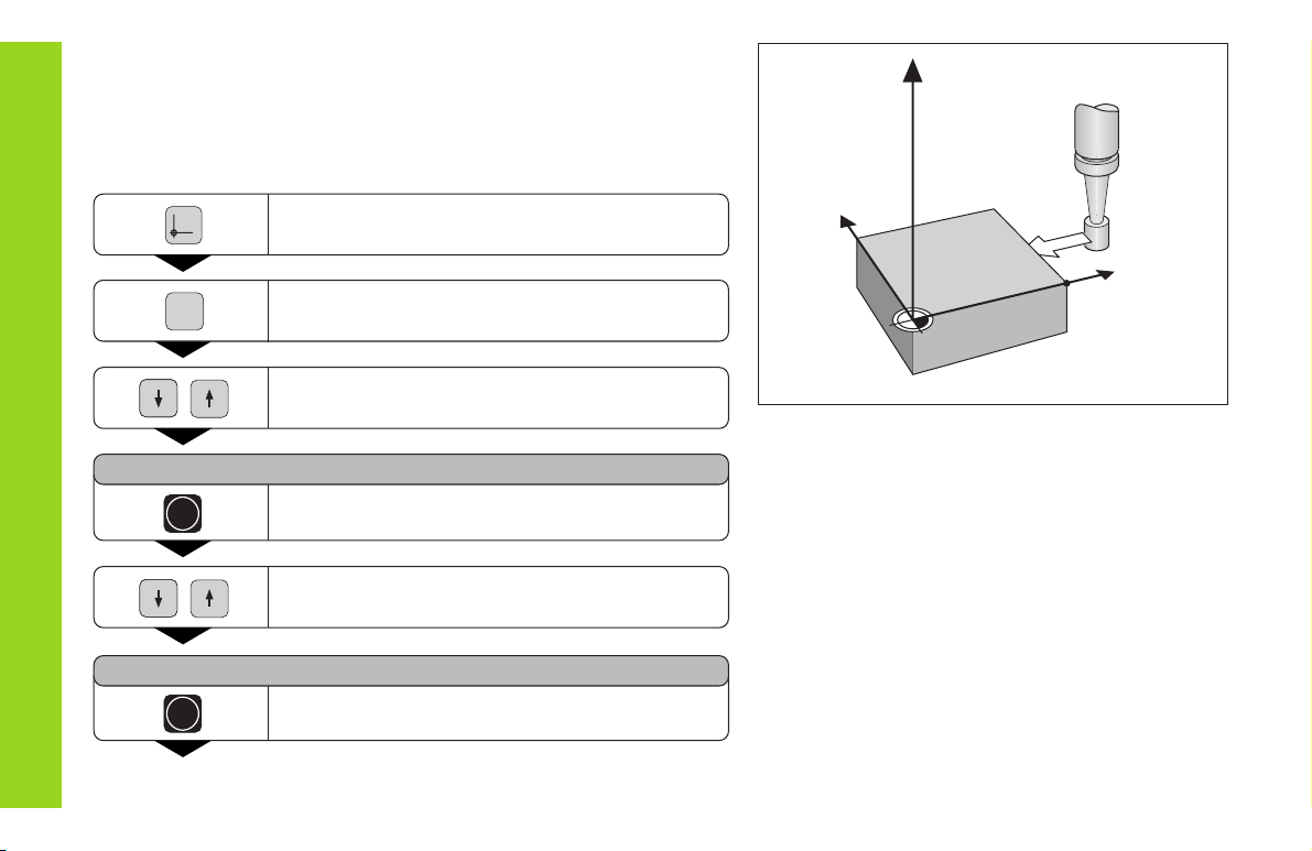
Probing a workpiece edge and setting it as a datum
The probed edge is parallel to the Y axis. For all coordinates of a datum
you can probe workpiece edges and surfaces as described below and
set them as datums.
Datum Setting
Y
X
Z
X?
Select the datum number.
Select special functions.
SPEC
FCT
Select PROBING FUNCTION.
PROBING FUNCTION ?
ENT
Confirm selection.
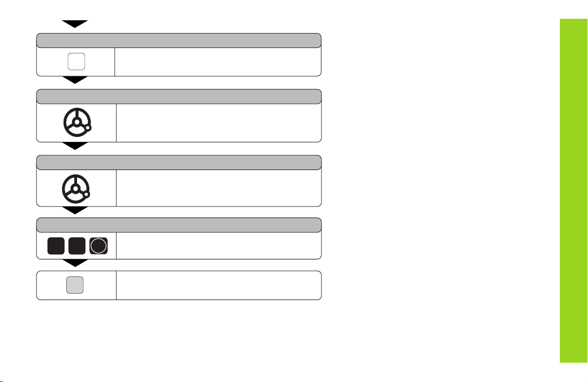
Select PROBE EDGE.
ENT
Confirm selection PROBE EDGE.
•
•
PROBE EDGE ?
15
Datum Setting
PROBE X
X
Select the X axis (if not already selected).
PROBE X
Move the edge finder towards the workpiece
edge until the LED in the edge finder lights up.
The position of the edge is now displayed.
POS.MEASURED X =
Retract the edge finder from the workpiece.
POS.MEASURED X =
5
2
Set the position value (for example 52) to this
edge.
SPEC
FCT
Leave the probing functions, or select a new axis.
ENT
16
Probing workpiece edges and setting the centerline as a datum
The probed edges should be parallel to the Y axis.
You can follow these instructions for any centerlines.
Datum Setting
Y
X
2
1
Z
M
X?
Select the datum number.
Select special functions.
SPEC
FCT
Select PROBING FUNCTION.
PROBING FUNCTION ?
ENT
Confirm selection.
Select PROBE MIDPOINT.
ENT
Confirm selection.
•
•
PROBE MIDPOINT ?
17
Datum Setting
1. PROBE POS. X
X
Select X axis (if not already selected).
1. PROBE POS. X
Move the edge finder against workpiece edge
until the LED in the edge finder lights up.
The position of the edge is now displayed.
2. PROBE POS. X
Move the edge finder against workpiece edge
until the LED in the edge finder lights up.
The position of the edge is now displayed.
POS.MEASURED X =
2 6
Enter the position value for the centerline
(for example 26).
SPEC
FCT
Leave the probing functions, or select a new
axis.
ENT
1
2

18
Resetting all axes to zero
To reset all axes to zero, simply press the key shown below. Note that
when you do this, the last actual position becomes the relative datum
and is not stored (incremental positioning). The status display then
shows “– –” instead of the datum number. Any datum points already
set remain in memory. You can activate these by entering the
corresponding datum point number.
This key resets all axis position displays to zero.
Datum Setting
19
Holding Positions
Your display unit has the capability to hold or “freeze” position values.
The tool can be repositioned without affecting the display. You can then
assign a new value to the stored position.
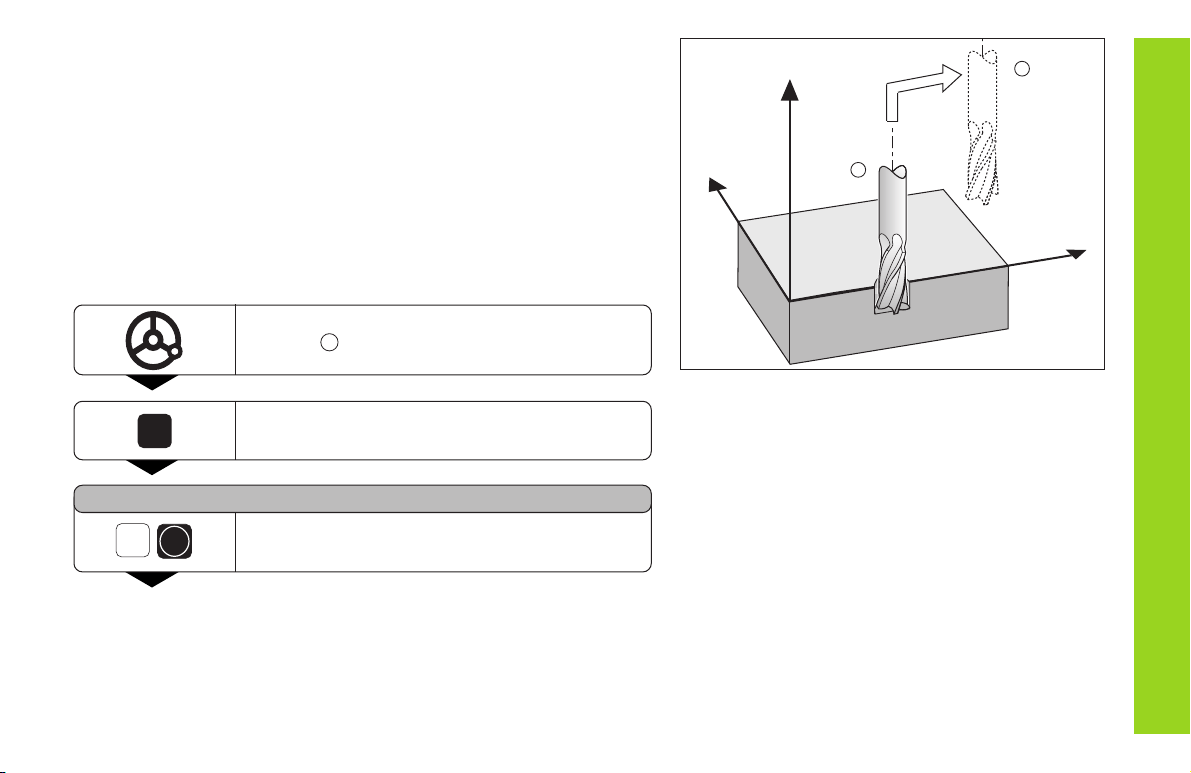
Example
Drill in the Z axis, measure the depth and set the datum to this depth.
Move to the desired position and drill in Z
direction .
HOLD
POS
Hold the position.
1)
KEEP Z POS. ?
Z
ENT
Store (hold) the position of the Z axis.
•
•
•
Y
X
Z
1
2
1
Holding Positions
1)
The HOLD POS key may have a different function. See the
section "Measured value output with the HOLD POS key".
20
Holding Positions
Y
X
Z
Z
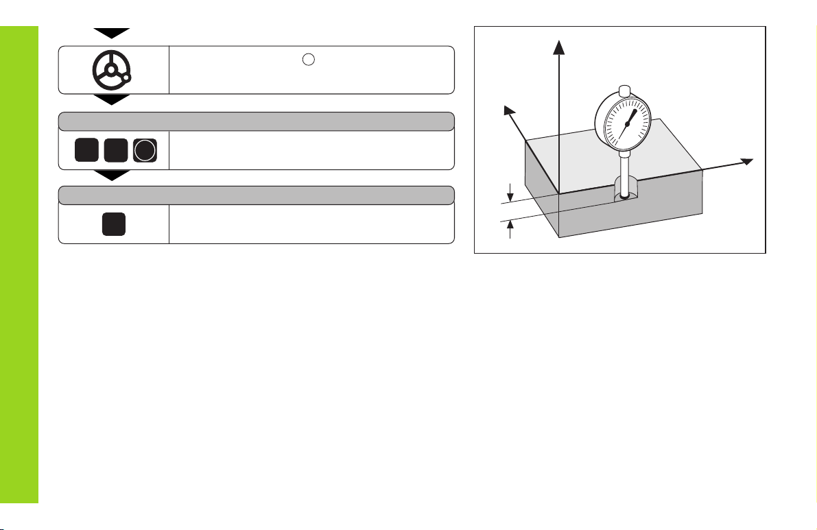
T
Retract tool to position and measure position
Z
T
.
SET POS. Z =
2
0
ENT
Set datum Z
T
(for example 20).
HOLD
POS
Leave HOLD POS or store position of another
axis.
KEEP Z POS. ?
2
21
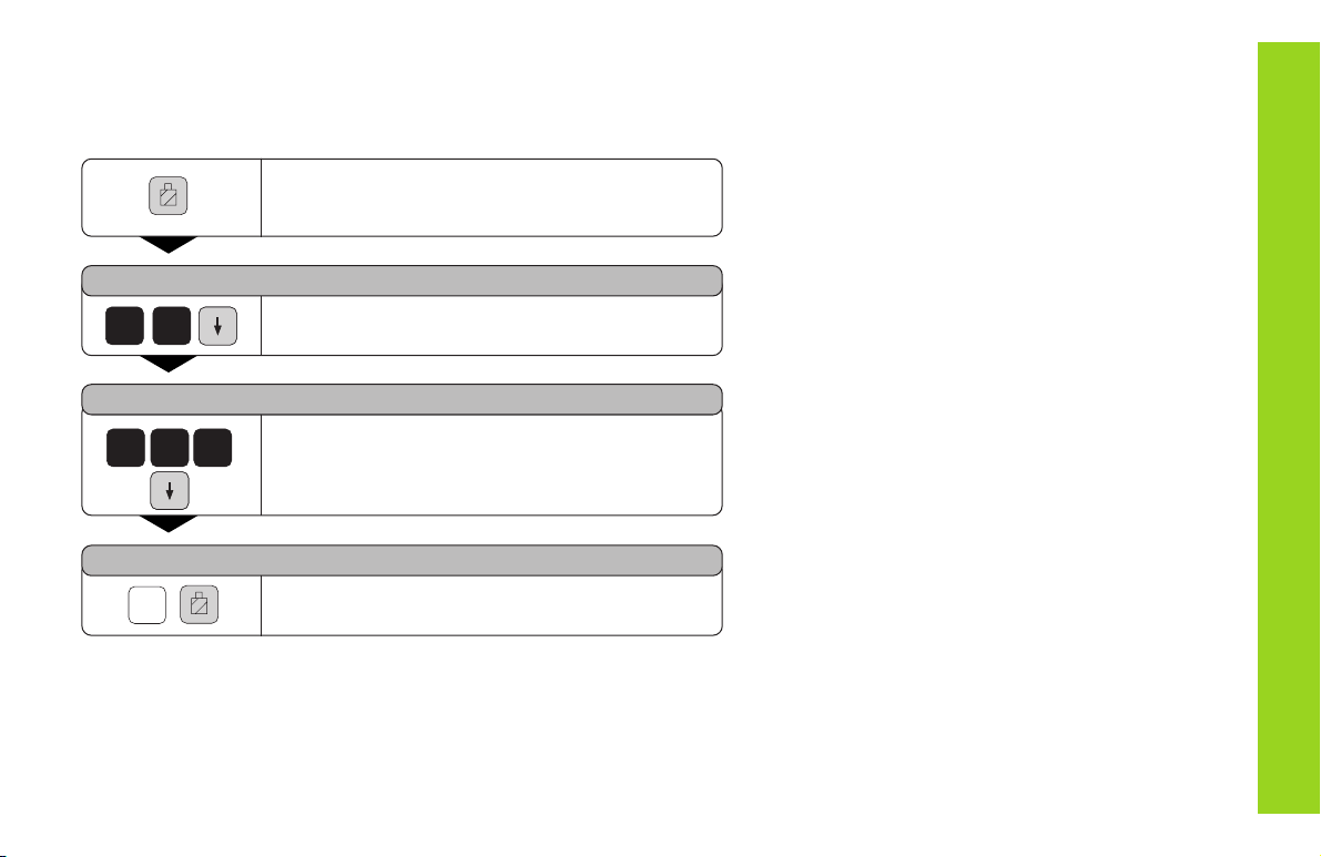
Tool Compensation
You can enter the tool axis, the tool length and the tool diameter for the
current tool.
Tool Compensation
Press the tool compensation key.
TOOL DIAMETER =
2 0
Enter the tool diameter (for example 20 mm),
and confirm with the arrow down key.
TOOL LENGTH =
0
0
2
Enter the tool length (for example 200 mm),
and confirm with the arrow down key.
TOOL AXIS =
Z
Enter the tool axis and end the function.
 Loading...