


User’s Manual
ND 281B
Measured Value Displays
English (en) 10/2002
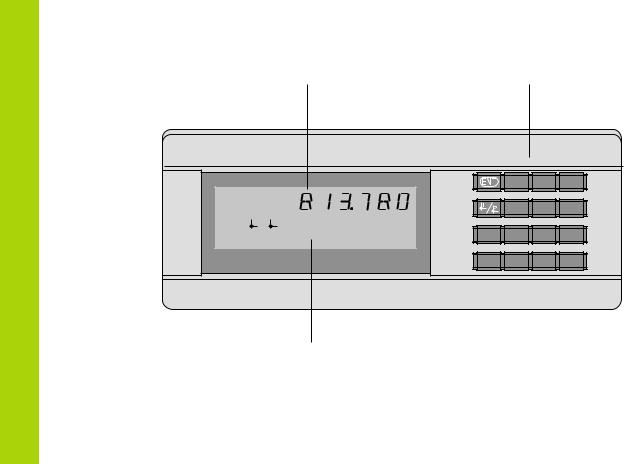
Display of actual value and input |
Numeric keypad |
(9 decades with algebraic sign) |
with decimal point |
|
|
|
|
|
|
|
|
7 |
8 |
9 |
|
|
|
|
|
|
|
|
4 |
5 |
6 |
REF |
1 |
2 |
SET |
START |
PRINT inch |
MOD |
1 |
2 |
3 |
|
< = > |
|
MIN |
ACTL |
MAX |
DIFF |
|||||
|
|
|
|
|
|
|
CL |
0 |
. |
– |
HEIDENHAIN |
|
|
|
|
|
|
|
|
||
Status display with indicators
2
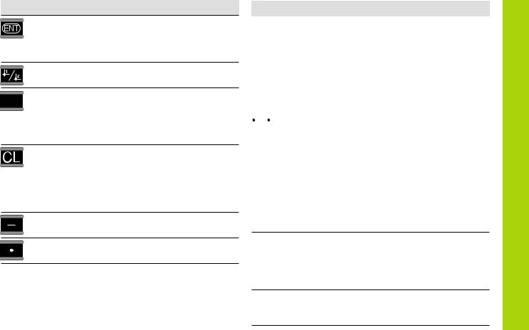
Key Function
•Set datum
•Transfer input value
•Set display to value from P79 (P80!)
•Leave parameter list
• Select datum
• Page backwards in parameter list
MOD |
• Select parameter after switch-on |
|
• Page forward in parameter list |
||
|
||
|
• Start series of measurements1) |
|
|
• Switch display for measurement series1) |
|
|
• Start measured value output “PRINT” |
|
|
• Delete entry |
|
|
• Set display to zero (P80!) |
|
|
• CL plus MOD: select parameter list |
|
|
• CL plus number: select parameter |
|
|
• Delete parameter input and show |
|
|
parameter number |
|
|
• Algebraic sign |
|
|
• Reduce parameter value |
|
|
• Decimal point |
|
|
• Increase parameter value |
|
Indicator |
Meaning |
|||||
REF |
If the decimal point is also blinking: |
||||||
|
|
|
|
|
|
|
Display is waiting for reference mark |
|
|
|
|
|
|
|
traversing. If decimal point is not blinking: |
|
|
|
|
|
|
|
Reference mark has been traversed—display |
|
|
|
|
|
|
|
stores datum points in nonvolatile memory |
|
|
|
|
|
|
|
Blinking: display is waiting for ENT or |
|
|
|
|
|
|
|
CL to be depressed |
|
|
|
|
|
|
|
|
inch |
Position values in inches |
||||||
|
|
|
|
|
|
|
|
|
1 / |
|
2 |
|
Selected datum point |
||
|
|
|
|||||
|
|
|
|
|
|
|
|
"Linear measurement” |
|||||||
|
|
|
|
|
|
|
Blinking: Display is waiting for ENT to |
|
|
|
|
|
|
|
be pressed for data output |
|
|
|
|
|
|
|
“Angular measurement” |
|
|
|
|
|
|
|
Measured value output with MOD key |
|
|
|
|
|
|
|
|
SET |
Blinking: Display is waiting for input values |
||||||
|
|
|
|
|
|
|
|
< / = / > |
Sorting and tolerance checking: |
||||||
|
|
|
|
|
|
|
measured value smaller than lower limit / |
|
|
|
|
|
|
|
within the limits / greater than upper limit |
MIN / MAX /
DIFF / ACTL1)
Series of measurements: Minimum / maximum / greatest difference (MAX–MIN) / current measured value
Blinking: Confirm selection or deselect function
1) Only in linear measurement mode.
START 1) |
Series of measurements is running |
|
Blinking: Display is waiting for signal to |
start series of measurements |
3 |
|

Items Supplied
4
Items supplied with ND 281 B
ND 281 B |
Measured value display unit, |
|
benchtop model |
Encoder input |
|
11 µAPP/1 VPP |
Id. Nr. 344 996-xx |
Power cord |
3 m (9.9 ft) |
|
|
User's Manual |
ND 281B |
|
|
Adhesive plug-in feet |
For stacking ND 281B units |
|
|
This manual is for the ND 281 B measured value display with the following software number or higher:
349 797-04
The software number is indicated on a label on the rear panel.

Contents
Working with the ND Display Units
Encoders |
6 |
Reference Marks |
7 |
|
|
Switch-On,Traversing the Reference Marks |
8 |
|
|
Datum Setting |
9 |
|
|
Finding Minimum and MaximumValues 1) |
10 |
Sorting andTolerance Checking |
13 |
|
|
MeasuredValue Output |
14 |
|
|
Display Freeze |
15 |
|
|
Error Messages |
16 |
1) Only in linear measurement mode
Installation and Specifications
Rear Panel, Accessories |
17 |
Mounting |
19 |
|
|
Power Connection |
20 |
Linear/Angular Measuring Modes |
21 |
Operating Parameters |
22 |
List of Operating Parameters |
24 |
|
|
Linear Encoders |
28 |
|
|
Angle Encoders |
33 |
|
|
MultipointAxis Error Compensation |
34 |
Switching Inputs and Outputs EXT (X41) |
38 |
Locking the Keypad |
43 |
Displaying the Software Version |
44 |
|
|
Distance-to-Go Mode |
45 |
|
|
RS-232-C/V.24 Data Interface (X31) |
46 |
|
|
Input/Output of Parameter and |
51 |
Compensation-Value Lists |
|
|
|
Output Format of the Parameter List |
53 |
Output Format of the Compensation-ValueTable |
57 |
Remote Operation over the RS-232-C/V.24 |
60 |
Data Interface |
|
|
|
Specifications |
63 |
Dimensions |
64 |
Contents
5

Position Encoders
Position Encoders
The ND 281 B display unit is designed for use with photoelectrical linear or angular encoders with sinusoidal signals: primarily for HEIDENHAIN MT length gauges.
When shipped by HEIDENHAIN, the display units are set to the linear measurement mode.
You can switch between the linear and angular modes by entering the code number 41 52 63 (see “Linear/Angular Measurement Modes”).
On the back of the display you will find two flange sockets for connecting the encoder: X1 for encoders with 11 µAPP sinusoidal current signals and X2 for 1 VPP sinusoidal voltage signals.
Before shipping, HEIDENHAIN activates the encoder connection X1 for 11 µAPP sinusoidal current signals. With parameter P02 you can activate the encoder input that matches your encoder (see “Operating Parameters”).
6
Reference Marks
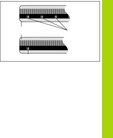
The MT length gauges have one reference mark. The scales of other photoelectric linear or angular encoders can contain one reference mark or many distance-coded reference marks.
If there is an interruption of power, the relationship between the position of the length gauge and the displayed position value is lost. The reference marks on the position encoders and the REF reference mark evaluation feature enable the display unit to quickly reestablish this relationship again when the power is restored.
When a reference mark is crossed over, a signal is generated which identifies that position as a reference point. At the same time, the display unit restores the relationship between length gauge position and display values which you last defined by setting the datum.
To restore the datum on scales with distance-coded reference marks, you only need to traverse a maximum of 20 mm for linear encoders, and 10° or 20° for angle encoders, depending on the model.
Scale in |
Distance-coded |
linear encoder |
reference marks |
Reference mark
Reference marks on linear encoders
Reference Marks
7
Switch-On, Traversing the Reference Marks
Switch-On, Traversing the Reference Marks
0 ä1 |
 ENT...CL
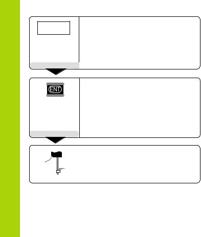
Turn on the power.
(Switch located on rear panel.)
•ND 281 B appears for two seconds.
•ENT ... CL 1) appears.
•REF indicator starts blinking.
Switch-on the reference mark evaluation function.
•The position value that was last assigned to the reference mark position is displayed.
•REF indicator lights.
•Decimal point starts blinking.
5 , 6 9 7 
|
|
Cross over the reference mark. |
|
Û |
Move the plunger until the display starts |
||
counting and the decimal point stops blink- |
|||
|
|
||
|
|
ing. The display is now ready for operation. |
|
|
|
||
|
|
|
|
For automation purposes, crossing over the reference marks and the display ENT ... CL can be disabled with parameter P82.
REF mode
Crossing over the reference marks automatically switches the display to REF mode: The last assignment of display values to length gauge positions is stored in nonvolatile memory.
1)Press the CL key if you choose not to traverse the reference marks. Note that, in this case, the relationship between length gauge position and display value will be lost if the power is interrupted or if the unit is switched off.
8
Datum Setting
The datum setting procedure assigns a display value to a known position. With the ND 200 series, you can set two separate datum points.
There are several ways to set the datum:
•Enter a numerical value, or
•Transfer a value from an operating parameter (see P79, P80), or
•By external signal
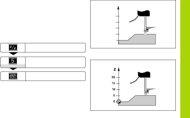
Select datum 1 or 2.
Enter a numerical value (here, 5).
SET starts blinking.
5
Z
?
?
?
?
?
Without datum setting: unknown assignment of measured values to positions
Confirm the entered numerical value.
You can switch between datums 1 and 2 as desired. Datum 2 can be used, for example, for working with incremental dimensions.
When you switch back to datum 1, the display unit resumes display of the encoder's actual position.
After datum setting: Assignment of measured values to positions
Datum Setting
9

Finding Minimum and Maximum Values
10
Finding Minimum and Maximum Values from a Series of Measurements1)
After a series of measurements has been started, the display transfers the first measured value to the memory for minimum and maximum values. Every 0.55 ms, the display compares the current measured value with the memory contents: A new value is stored if it is greater than the stored maximum value or smaller than the stored minimum value. At the same time, the display calculates and stores the difference DIFF between the current MIN and MAX values.
Display |
Meaning |
MIN |
Minimum value from the series of measurements |
|
|
MAX |
Maximum value from the series of measurements |
|
|
DIFF |
Difference MAX – MIN |
|
|
ACTL |
Current measured value |
|
|
Starting the measurement series and selecting the display
You can start the series of measurements either by pressing MOD and selecting the desired display—as described on the following pages—or by external signal over the switching inputs at the D-sub connection EXT (X41, see “Switching Inputs and Outputs”).
When a series of measurements is started, the internal MIN/ MAX/DIFF memory is reset.
1) Only in the linear measurement mode.
MAX |
ACTL |
DIFF |
MIN |
Series of measurements: The MIN, MAX and DIFF values of an uneven surface
Example: Measurement series for determining eccentricity e
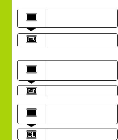
Starting a series of measurements |
Switching between MIN, MAX, DIFF and ACTL displays |
Repeatedly
MOD |
MAX
Select the display for a series of measurements.
The selected indicator starts blinking (here, MAX).
Confirm selection.
It is not possible to switch between the displays as described below if the switching input for external control of the series of measurements (pin 6 on D-sub connection EXT) is active.
As an alternative, you can select the display with operating parameter P21 (see "Operating Parameters").
Repeatedly |
... until the START indicator starts blinking. |
|
|
MOD |
|
START |
|
Repeatedly
MOD |
MIN
Select the new display of a series of measurements.
The selected indicator starts blinking (here, MIN).
Start the series of measurements.
Indicator preselection
Press MOD to start the series of measurements and select the display with the indicators.
Operating parameter P86 allows you to define which indicator is displayed first when MOD is pressed.
Confirm the change.
The display now shows the smallest value measured during the current series of measurements.
Finding Minimum and Maximum Values
11
Finding Minimum and Maximum Values
12
Starting a new series of measurements
Repeatedly
MOD |
START
Select the indicator START.
The START indicator starts blinking.
|
Start a new series of measurements. |
Ending a series of measurements |
|
Repeatedly |
Select the active indicator (MIN, ACTL, |
|
|
MOD |
MAX, DIFF). |
|
The indicator that lit up last starts blinking. |
or
Repeatedly
MOD |
START
End the series of measurements.
Select the indicator START.
The START indicator starts blinking.
End the series of measurements.

Sorting and Tolerance Checking |
|
|
Checking |
|
In the sorting and tolerance checking mode, the display unit |
|
|
||
|
|
|
||
compares the displayed value with the programmed upper and |
|
|
|
|
lower sorting limits. The sorting and tolerance checking mode is |
|
|
|
|
enabled and disabled with operating parameter P17. |
|
|
Tolerance |
|
Entering sorting limits |
Part 1 |
|
||
|
|
|||
Sorting limits are entered in operating parameters P18 and P19 |
|
Accept |
|
|
(see operating parameters). |
|
|
and |
|
Sorting signals |
|
|
||
|
|
|
||
The indicators and switching outputs at D-sub connection EXT |
Part 2 |
|
Sorting |
|
(see section on X41) sort the display value into one of three |
|
|||
|
|
|
||
classes. |
|
|
|
|
Display |
Meaning |
|
Rework |
|
= |
Measured value is within sorting limits |
|
|
|
|
|
|
||
< |
Measured value is smaller than lower sorting limit |
|
|
|
> |
Measured value is greater than upper sorting limit |
|
|
|
Operating parameters for sorting and tolerance checking |
|
|
|
|
P17 CLASS |
Sorting ON/OFF |
Part 3 |
|
|
|
|
|
|
|
P18 L.CLASS. Lower sorting limit |
|
Reject |
|
|
|
|
|
|
|
P19 U.CLASS. Upper sorting limit |
|
|
|
|
Example: Upper sorting limit = 26.02 mm |
13 |
|
|
Lower sorting limit = 26.00 mm |
|

Measured Value Output
Measured Value Output
For technical information on the RS-232-C/V.24 data interface (X31), information on the data format, etc., see the chapter “RS-232-C/V.24 Data Interface (X31).”
Measured values can be transmitted over the RS-232-C/V.24 interface (X31), for example to a printer or PC.
There are several ways to start measured value output:
äIn the linear measurement mode:
Press MOD repeatedly until the PRINT indicator starts blinking, then start measured value output with ENT. In the angular measurement mode:
Press the MOD key (this feature can be disabled with operating parameter 86).
or
äInput the command STX (Ctrl B) over the RXD input of the
RS-232-C/V.24 interface (X31); or
äInput a signal for measured data output (Pulse or Contact) at the D-sub connection EXT (X41).
|
|
|
|
|
|
|
|
|
|
|
PC |
|
|
|
|
|
|
|
|
|
7 |
8 |
9 |
|
|
|
|
|
|
|
|
|
4 |
5 |
6 |
REF |
|
1 |
2 |
SET |
START PRINT |
in. |
MOD |
1 |
2 |
3 |
|
< |
= |
> |
MIN |
ACTL |
MAX |
DIFF |
CL |
0 |
. |
– |
|
HEIDENHAIN |
|
|
|
|
|
|
|
|
|||
The RS-232-C/V.24 interface (X31) enables you to connect a printer or a PC to your display unit
14

Display Freeze
With the latch command, the display can be stopped for any period of time. The internal counter remains active. Parameter P23 selects the “display freeze” mode and offers three settings:
•Concurrent display, no display freeze—the display value is the current measured value.
•Frozen display—display value is frozen and is updated with each signal for measured value output.
•Frozen/concurrent display—display remains frozen as long as the latch signal is present; after the signal, the display resumes continuous display of the current measured values.
Position
Latch signal
Frozen
display
Frozen/ concurrent display
Display Freeze
15

Error Messages
Error Messages
Display |
Effect/Cause |
RS232 FAST |
Command for measured value |
|
output followed too quickly by |
|
another. 1) |
SIGNAL |
Encoder signal is too weak. |
|
The scale may be contaminated.1) |
DSR.MISSING |
The connected device has not sent |
|
a DSR signal.1) |
REF. ERR. |
The spacing of the reference marks |
|
as defined in P43 is not the actual |
|
spacing.1) |
FORMAT ERR. |
Data format, baud rate, etc. do not |
|
match.1) |
FREQUENCY |
Input frequency too high for encoder |
|
input. Traversing speed may be |
|
too fast.1) |
MEMORY ERR. |
Checksum error: Check the datum, |
|
operating parameters and compen- |
|
sation values for multipoint axis |
|
error compensation. If this error |
|
recurs, contact your service |
|
agency! |
1)These errors are important for the attached device. The error signal (pin 19) at D-sub connection EXT is active.
Display |
Effect/Cause |
REC. ERROR |
Error during reception of param- |
|
eter and compensation-value lists. |
|
|
Other Error displays
If “OVERFLOW” appears, the measured value is too large or too small:
äSet a new datum. or
äTraverse back.
If all sorting signals light up, the upper sorting limit is smaller than the lower limit:
ä Change operating parameters P18 and/or P19.
To clear error messages:
Once you have removed the cause of the error: ä Clear the error message with the CL key.
16
Rear Panel
Ports X1, X2, X31 and X41 comply with the recommendations in EN 50 178 for separation from line power.
Encoder input X1
HEIDENHAIN flange socket |
9-pin |
|
|
Input signals |
11 µAPP |
|
|
Maximum encoder cable length |
30 m (98.5 ft) |
||
|
|
|
|
Maximum input frequency |
100 kHz |
||
|
|
|
|
|
|
|
|
|
Encoder input X2 |
|
|
|
|
|
|
|
HEIDENHAIN flange socket |
12-pin |
|
|
|
|
|
|
Input signals |
1 VPP |
|
|
Maximum encoder cable length |
60 m (197 ft) |
|
|
|
|
|
|
Maximum input frequency |
500 kHz |
|
|
|
|
|
Rear Panel, Accessories
17

Rear Panel, Accessories
Rear Panel
Ports X1, X2, X31 and X41 comply with the recommendations in EN 50 178 for separation from line power.
RS-232-C/V.24 data interface (X31)
25-pin D-sub connection (female)
Switching inputs and outputs EXT (X41)
Data interface |
|
D-sub |
|||
|
|
|
|
connection |
|
|
|
|
|
|
|
|
|
|
|
|
|
25-pin D-sub connection (male)
Power switch
Accessories
Connecting elements
Connector (female) |
25-pin for D-sub connection X41 |
|
Id. Nr. 249 154 ZY |
Ground connection
Input X1 for one HEIDENHAIN 11 µAPP encoder
Input X2 for one HEIDENHAIN
1 VPP encoder
Connector (male) |
25-pin for D-sub connection X31 |
|
Id. Nr. 245 739 ZY |
|
|
Data interface cable, |
3 m (9.9 ft), 25-pin for D-sub con- |
complete |
nection X31, Id. Nr. 274 545-01 |
|
|
18
Mounting
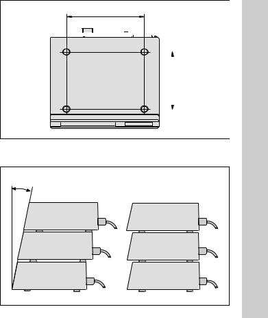
172 ± 0.2
You can fasten the ND 281 B from below by using M4 screws 6.77 ± .008" (see illustration at right). 


|
|
|
|
|
|
Mounting |
||
|
|
|
|
|
|
|
|
|
|
|
|
140 ± 0.2 |
|
5.51 ± .008" |
|||
|
|
|
|
|||||
|
|
|
|
|
|
|
|
|
|
|
|
|
|
|
|
|
|
ND 281 B display units are stackable. Adhesive plug-in feet (supplied with your unit) prevent the stacked units from being moved out of place.
Hole positions for mounting the ND display unit
15° |
|
Alternatives of stacking the display units |
19 |

Power Connection
Power Connection
The rear panel of the ND 281 B contains a connecting jack for a power cord with Euro connector (power cord supplied with the delivery).
Minimum cross section of the power cord: 0.75 mm2
Power supply: 100 Vac to 240 Vac (–15% to +10%) 50 Hz to 60 Hz (± 2 Hz)
A voltage selector is therefore not necessary.
Danger of electrical shock!
Unplug the power cord before opening the housing. Connect the grounding conductor. Do not interrupt the grounding conductor.
Danger to internal components!
Do not engage or disengage any connections while the unit is under power. Use only original replacement fuses.
To increase noise immunity, connect the ground terminal on the rear panel to the central ground point of the machine.
(Minimum cross-section: 6 mm2)
20
 Loading...