


 HEIDENHAIN
User's Manual
ISO Programming
TNC 360
February 1994
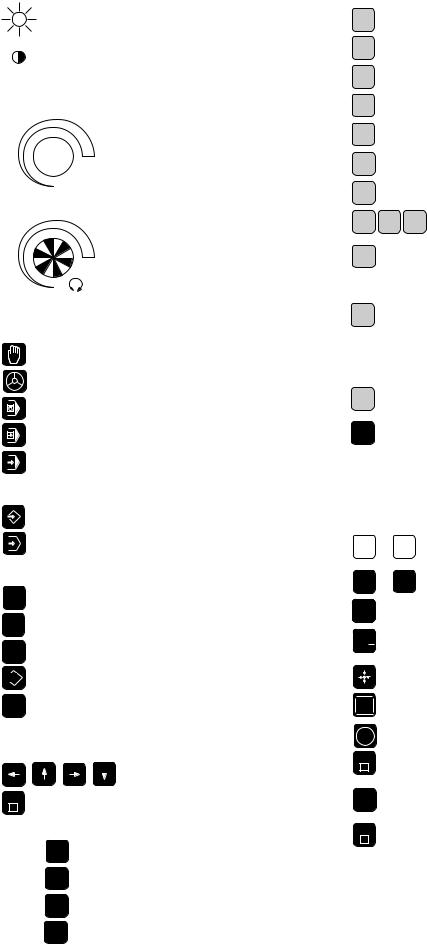
Keys and Controls on the TNC 360
Controls on the Visual Display Unit
|
Brightness |
|
Contrast |
Override Knobs |
|
100 |
Feed rate |
|
|
50 |
150 |
 F %
F %
0
100
Spindle speed
50 |
150 |
S %
0
Machine Operating Modes
MANUAL OPERATION
ELECTRONICHANDWHEEL
POSITIONING WITH MANUAL DATA INPUT
PROGRAM RUN, SINGLE BLOCK
PROGRAMRUN,FULLSEQUENCE
Programming Modes
|
PROGRAMMING AND EDITING |
|
TESTRUN |
Program and File Management |
|
PGM |
Select programs and files |
NR |
|
CL |
Delete programs and files |
PGM |
|
PGM |
Enter program call in a program |
CALL |
|
EXT |
External data transfer |
|
|
MOD |
Supplementary modes |
|
Moving the Cursor and Selecting Blocks, Cycles and Parameter Functions with GOTO
GOTO
Graphics
MOD
BLK
FORM
MAGN
START
Move the cursor (highlight)
Go directly to blocks, cycles and parameter functions
Graphic operating modes
Define blank form, reset blank form
Magnify detail
Start graphic simulation
Address Letters for ISO Programming
N |
Block number |
|
G |
G function |
|
F |
Feed rate / Dwell time with G04 / Scaling factor |
|
M |
Miscellaneous function (M function) |
|
S |
Spindle speed in rpm |
|
D |
Parameter definition |
|
H |
Polar angle/Rotation angle in cycle G73 |
|
I J |
K X, Y, Z coordinate of circle center/pole |
|
L |
Assign a label number with G98/ |
|
Jump to a label number/ |
||
|
Tool length with G99 |
|
R |
Polar radius/ |
|
Rounding radius with G25, G26, G27 |
||
|
Chamfer with G24 |
|
|
Circle radius with G02, G03, G05 |
|
|
Tool radius with G99 |
|
T |
Tool definition with G99/ |
|
Tool call |
||
|
||
TOUCH |
Set a datum with the 3D touch probe system |
|
PROBE |
||
|
Entering Numbers and Coordinate Axes, Editing
X ... |
IV |
Select or enter coordinate axes |
|
in a program |
|||
|
|
||
0 ... |
9 Numbers |
||
. |
|
Decimal point |
|
|
|
||
+/ |
|
Algebraic sign |
|
|
|
Actual position capture |
|
NO |
|
Ignore dialog queries, delete words |
|
ENT |
|
||
|
|
||
ENT |
|
Confirm entry and resume dialog |
|
END |
|
Conclude block |
|
|
|
||
Clear numerical entry
CE |
or TNC message |
|
|
DEL |
Abort dialog; delete program sections |
|
TNC Guideline:
From workpiece drawing to program-controlled machining
Step |
Task |
TNC |
|
Refer to |
|
|
operating mode |
Section |
|
|
Preparation |
|
|
|
1 |
Select tools |
—— |
|
—— |
2 |
Set workpiece datum |
|
|
|
|
for coordinate system |
—— |
|
—— |
3 |
Determine spindle speeds |
|
|
|
|
and feed rates |
—— |
|
11.4 |
4 |
Switch on machine |
—— |
|
1.3 |
5 |
Traverse reference marks |
or |
|
1.3, 2.1 |
6 |
Clamp workpiece |
—— |
|
—— |
7 |
Set the datum / |
|
|
|
|
Reset position display ... |
|
|
|
7a |
... with the 3D touch probe |
or |
|
2.5 |
7b |
... without the 3D touch probe |
or |
|
2.3 |
|
Entering and testing part programs |
|
|
|
8 |
Enter part program |
|
|
|
|
or download |
|
|
|
|
over external |
|
|
5 to 8 |
|
data interface |
or |
EXT |
or 10 |
9 |
Test part program for errors |
|
|
3.1 |
10 |
Test run: Run program |
|
|
|
|
block by block without tool |
|
|
3.2 |
11 |
If necessary: Optimize |
|
|
|
|
part program |
|
|
5 to 8 |
|
Machining the workpiece |
|
|
|
12 |
Insert tool and |
|
|
|
|
run part program |
|
|
3.2 |

Sequence of Program Steps
Milling an outside contour
|
Programming step |
Key/Function |
Refer to Section |
|
|
|
|
||
1 Create or select program |
PGM |
4.4 |
||
|
Input: |
Program number |
|
|
|
NR |
|
||
|
|
Unit of measure for programming |
|
|
2 Define workpiece blank for graphic display |
G30/G31 |
4.4 |
||
3 |
Define tool(s) |
G99 |
4.2 |
|
|
Input: |
Tool number |
T... |
|
|
|
Tool length |
L... |
|
|
|
Tool radius |
R... |
|
4 |
Call tool data |
T... |
4.2 |
|
|
Input: |
Tool number |
|
|
|
|
Spindle axis |
G17 |
|
|
|
Spindle speed |
S... |
|
5 Tool change |
|
|
|
|
|
Input: |
Feed rate (rapid traverse) |
G00 |
e.g. 5.4 |
|
|
Radius compensation |
G40 |
|
|
|
Coordinates of the tool change position |
X... Y... Z... |
|
|
|
Miscellaneous function (tool change) |
M06 |
|
6 Move to starting position |
|
5.2/5.4 |
||
|
Input: |
Feed rate (rapid traverse) |
G00 |
|
|
|
Coordinates of the starting position |
X... Y... |
|
|
|
Radius compensation |
G40 |
|
|
|
Miscellaneous function (spindle on, clockwise) |
M03 |
|
7 Move tool to (first) working depth |
|
5.4 |
||
|
Input: |
Feed rate (rapid traverse) |
G00 |
|
|
|
Coordinate of the (first) working depth |
Z... |
|
8 Move to first contour point |
|
5.2/5.4 |
||
|
Input: |
Linear interpolation |
G01 |
|
|
|
Radius compensation for machining |
G41/G42 |
|
|
|
Coordinates of the first contour point |
X... Y... |
|
|
|
Machining feed rate |
F... |
|
if desired, with smooth approach: program G26 after this block |
|
|
||
9 Machining to last contour point |
|
5 to 8 |
||
|
Input: |
Enter all necessary values for |
|
|
|
|
each contour element |
|
|
if desired, with smooth departure: program G27 after the last |
|
|
||
radius-compensated block |
|
|
||
10 Move to end position |
|
5.2/5.4 |
||
|
Input: |
Feed rate (rapid traverse) |
G00 |
|
|
|
Cancel radius compensation |
G40 |
|
|
|
Coordinates of the end position |
X... Y... |
|
|
|
Miscellaneous function (spindle stop) |
M05 |
|
11 Retract tool in spindle axis |
|
5.2/5.4 |
||
|
Input: |
Feed rate (rapid traverse) |
G00 |
|
|
|
Coordinate above the workpiece |
Z... |
|
|
|
Miscellaneous function (end of program) |
M02 |
|
12 End of program |
|
|
||
|
|
|
|
|

How to use this manual
This manual describes functions and features available on the TNC 360 from NC software number 259 900 08.
This manual describes all available TNC functions. However, since the machine builder has modified (with machine parameters) the available range of TNC functions to interface the control to his specific machine, this manual may describe some functions which are not available on your TNC.
TNC functions which are not available on every machine are, for example:
•Probing functions for the 3D touch probe system
•Rigid tapping
If in doubt, please contact the machine tool builder.
TNC programming courses are offered by many machine tool builders as well as by HEIDENHAIN. We recommend these courses as an effective way of improving your programming skill and sharing information and ideas with other TNC users.
TNC 360

The TNC beginner can use the manual as a workbook. The first part of the manual deals with the basics of NC technology and describes the TNC functions. It then introduces the techniques of conversational programming. Each new function is thoroughly described when it is first introduced, and the numerous examples can be tried out directly on the TNC. The TNC beginner should work through this manual from beginning to end to ensure that he is capable of fully exploiting the features of this powerful tool.
For the TNC expert, this manual serves as a comprehensive reference work. The table of contents and cross references enable him to quickly find the topics and information he needs. Easy-to-read dialog flowcharts show him how to enter the required data for each function.
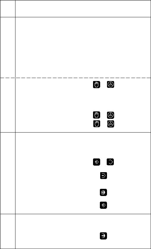
The dialog flow charts consist of sequentially arranged instruction boxes. Each key is illustrated next to an explanation of its function to aid the beginner when he is performing the operation for the first time. The experienced user can use the key sequences illustrated in the left part of the flowchart as a quick overview. The TNC dialogs in the instruction boxes are always presented on a gray background.
Layout of the dialog flowcharts
Dialog initiation keys
G 8 3 |
DIALOG PROMPT (ON TNC SCREEN) |
|
||
|
e.g. 8 3 |
ENT |
The functions of the keys are explained here. |
|
|
|
|
|
|
|
Answer the prompt with |
|
|
|
|
these keys |
|
|
|
|
NEXT DIALOG QUESTION |
|
|
|
|
|
|
Function of the key. |
|
|
Press this key |
|
|
A dashed line means that either |
|
|
|
|
the key above or below it can be |
|
+/ |
|
Function of an alternative key. |
pressed. |
|
|
|
|
|
|
Or press this key |
|
|
|
|
. |
|
The trail of dots indicates that: |
|
|
. |
|
|
|
|
. |
|
• the dialog is not fully shown, or |
|
•the dialog continues on the next page.
TNC 360

Contents User's Manual TNC 360
ISO Programming
Introduction
Manual Operation and Setup
Test Run and Program Run
Programming
Programming Tool Movements Subprograms and Program Section Repeats Programming with Q Parameters
Cycles
External Data Transfer
MOD-Functions
Tabels, Overviews and Diagrams
1
2
3
4
5
6
7
8
9
10
11

1 Introduction
1.1 The TNC 360 .......................................................................................... |
1-2 |
The Operating Panel .................................................................................................... |
1-3 |
The Screen .................................................................................................................. |
1-3 |
TNC Accessories ......................................................................................................... |
1-5 |
1.2 Fundamentals of Numerical Control (NC) .......................................... |
1-6 |
Introduction ................................................................................................................. |
1-6 |
What is NC? ................................................................................................................ |
1-6 |
The part program ......................................................................................................... |
1-6 |
Programming ............................................................................................................... |
1-6 |
Reference system ....................................................................................................... |
1-7 |
Cartesian coordinate system ....................................................................................... |
1-7 |
Additional axes ............................................................................................................ |
1-8 |
Polar coordinates ......................................................................................................... |
1-8 |
Setting the pole ........................................................................................................... |
1-9 |
Setting the datum ........................................................................................................ |
1-9 |
Absolute workpiece positions ................................................................................... |
1-11 |
Incremental workpiece positions .............................................................................. |
1-11 |
Programming tool movements .................................................................................. |
1-13 |
Position encoders ...................................................................................................... |
1-13 |
Reference marks ...................................................................................................... |
1-13 |
1.3 |
Switch-On ........................................................................................... |
1-14 |
1.4 |
Graphics and Status Display ............................................................. |
1-15 |
|
Plan view ................................................................................................................... |
1-15 |
|
Projection in three planes .......................................................................................... |
1-16 |
|
3D view .................................................................................................................... |
1-16 |
|
Status display ............................................................................................................ |
1-18 |
1.5 Programs ............................................................................................. |
1-19 |
Program directory ...................................................................................................... |
1-19 |
Selecting, erasing and protecting programs .............................................................. |
1-20 |
TNC 360

2 Manual Operation and Setup
2.1 Moving the Machine Axes ................................................................... |
2-2 |
Traversing with the machine axis direction buttons .................................................... |
2-2 |
Traversing with the electronic handwheel .................................................................. |
2-3 |
Working with the HR 330 Electronic Handwheel ........................................................ |
2-3 |
Incremental jog positioning ......................................................................................... |
2-4 |
Positioning with manual data input (MDI) ................................................................... |
2-4 |
2.2 Spindle Speed S, Feed Rate F and Miscellaneous Function M ........ |
2-5 |
To enter the spindle speed S ...................................................................................... |
2-5 |
To enter the miscellaneous function M ....................................................................... |
2-6 |
To change the spindle speed S ................................................................................... |
2-6 |
To change the feed rate F ........................................................................................... |
2-6 |
2.3 |
Setting the Datum without a 3D Touch Probe .................................. |
2-7 |
|
Setting the datum in the tool axis ............................................................................... |
2-7 |
|
Setting the datum in the working plane ...................................................................... |
2-8 |
2.4 |
3D Touch Probe System ...................................................................... |
2-9 |
|
3D Touch probe applications ....................................................................................... |
2-9 |
|
Selecting the touch probe menu ................................................................................. |
2-9 |
|
Calibrating the 3D touch probe .................................................................................. |
2-10 |
|
Compensating workpiece misalignment ................................................................... |
2-12 |
2.5 |
Setting the Datum with the 3D Touch Probe System .................... |
2-14 |
|
Setting the datum in a specific axis .......................................................................... |
2-14 |
|
Corner as datum ........................................................................................................ |
2-15 |
|
Circle center as datum .............................................................................................. |
2-17 |
2.6 |
Measuring with the 3D Touch Probe System .................................. |
2-19 |
|
Finding the coordinate of a position on an aligned workpiece .................................. |
2-19 |
|
Finding the coordinates of a corner in the working plane ......................................... |
2-19 |
|
Measuring workpiece dimensions ............................................................................ |
2-20 |
|
Measuring angles ...................................................................................................... |
2-21 |
TNC 360

3 Test Run and Program Run
3.1 |
Test Run ................................................................................................ |
3-2 |
|
To do a test run ........................................................................................................... |
3-2 |
3.2 |
Program Run ......................................................................................... |
3-3 |
|
To run a part program .................................................................................................. |
3-3 |
|
Interrupting machining ................................................................................................ |
3-4 |
|
Resuming program run after an interruption ............................................................... |
3-5 |
3.3 |
Blockwise Transfer: Executing Long Programs ................................. |
3-6 |
|
Jumping over blocks ................................................................................................... |
3-7 |
TNC 360
4 Programming
4.1 |
Editing Part Programs .......................................................................... |
4-2 |
|
Layout of a program .................................................................................................... |
4-2 |
|
Editing functions .......................................................................................................... |
4-3 |
4.2 |
Tools ...................................................................................................... |
4-5 |
|
Determining tool data .................................................................................................. |
4-5 |
|
Entering tool data into the program ............................................................................. |
4-7 |
|
Entering tool data in program 0 ................................................................................... |
4-8 |
|
Calling tool data ........................................................................................................... |
4-9 |
|
Tool change ................................................................................................................. |
4-9 |
4.3 |
Tool Compensation Values ............................................................... |
4-11 |
|
Effect of tool compensation values ........................................................................... |
4-11 |
|
Tool radius compensation ......................................................................................... |
4-11 |
|
Machining corners ..................................................................................................... |
4-13 |
4.4 |
Program Creation ............................................................................... |
4-14 |
|
To create a new part program ................................................................................... |
4-14 |
|
Defining the blank form ............................................................................................. |
4-14 |
4.5 |
Entering Tool-Related Data ............................................................... |
4-17 |
|
Feed rate F ................................................................................................................ |
4-17 |
|
Spindle speed S ......................................................................................................... |
4-18 |
4.6 |
Entering Miscellaneous Functions and STOP .................................. |
4-19 |
4.7 |
Actual Position Capture ..................................................................... |
4-20 |
TNC 360

5 Programming Tool Movements
5.1 |
General Information on Programming Tool Movements ................. |
5-2 |
5.2 |
Contour Approach and Departure ...................................................... |
5-4 |
|
Starting and end positions ........................................................................................... |
5-4 |
|
Smooth approach and departure ................................................................................. |
5-6 |
5.3 |
Path Functions ...................................................................................... |
5-7 |
|
General information ..................................................................................................... |
5-7 |
|
Machine axis movement under program control ........................................................ |
5-7 |
|
Overview of path functions ......................................................................................... |
5-9 |
5.4 |
Path Contours - Cartesian Coordinates ............................................ |
5-10 |
|
Straight line at rapid traverse G00 ............................................................................. |
5-10 |
|
Straight line with feed rate G01 F ... ......................................................................... |
5-10 |
|
Chamfer G24 ............................................................................................................. |
5-13 |
|
Circles and circular arcs - General information .......................................................... |
5-15 |
|
Circle center I, J, K ................................................................................................... |
5-16 |
|
Circular path G02/G03/G05 around the circle center I, J, K ...................................... |
5-18 |
|
Circular path G02/G03/G05 with defined radius ........................................................ |
5-21 |
|
Circular path G06 with tangential connection............................................................ |
5-24 |
|
Corner rounding G25 ................................................................................................. |
5-26 |
5.5 |
Path Contours - Polar Coordinates ................................................... |
5-28 |
|
Polar coordinate origin: Pole I, J, K ........................................................................... |
5-28 |
|
Straight line at rapid traverse G10 ............................................................................. |
5-28 |
|
Straight line with feed rate G11 F ... ......................................................................... |
5-28 |
|
Circular path G12/G13/G15 around pole I, J, K .......................................................... |
5-30 |
|
Circular path G16 with tangential connection............................................................ |
5-32 |
|
Helical interpolation ................................................................................................... |
5-33 |
5.6 |
M Functions for Contouring Behavior and Coordinate Data.......... |
5-36 |
|
Smoothing corners: M90 ........................................................................................... |
5-36 |
|
Machining small contour steps: M97 ........................................................................ |
5-37 |
|
Machining open contours: M98 ................................................................................ |
5-38 |
|
Programming machine-referenced coordinates: M91/M92 ...................................... |
5-39 |
5.7 |
Positioning with Manual Data Input (MDI) ...................................... |
5-41 |
TNC 360

6 Subprograms and Program Section Repeats
6.1 Subprograms ........................................................................................ |
6-2 |
Principle ...................................................................................................................... |
6-2 |
Operating limits ........................................................................................................... |
6-2 |
Programming and calling subprograms ....................................................................... |
6-3 |
6.2 Program Section Repeats .................................................................... |
6-5 |
Principle ...................................................................................................................... |
6-5 |
Programming notes ..................................................................................................... |
6-5 |
Programming and calling a program section repeat .................................................... |
6-5 |
6.3 Main Program as Subprogram ............................................................ |
6-8 |
Principle ...................................................................................................................... |
6-8 |
Operating limits ........................................................................................................... |
6-8 |
To call a main program as a subprogram .................................................................... |
6-8 |
6.4 |
Nesting .................................................................................................. |
6-9 |
|
Nesting depth .............................................................................................................. |
6-9 |
|
Subprogram in a subprogram ...................................................................................... |
6-9 |
|
Repeating program section repeats .......................................................................... |
6-11 |
|
Repeating subprograms ............................................................................................ |
6-12 |
TNC 360

7 Programming with Q Parameters
7.1 |
Part Families — Q Parameters Instead of Numerical Values |
........... 7-3 |
7.2 |
Describing Contours Through Mathematical Functions................... |
7-5 |
|
Overview ..................................................................................................................... |
7-5 |
7.3 |
Trigonometric Functions ..................................................................... |
7-7 |
|
Overview ..................................................................................................................... |
7-7 |
7.4 |
If-Then Operations with Q Parameters .............................................. |
7-8 |
|
Jumps ...................................................................................................................... |
7-8 |
|
Overview ..................................................................................................................... |
7-8 |
7.5 |
Checking and Changing Q Parameters ............................................. |
7-10 |
7.6 |
Output of Q Parameters and Messages ........................................... |
7-11 |
|
Displaying error messages ........................................................................................ |
7-11 |
|
Output through an external data interface ................................................................ |
7-11 |
|
Assigning values for the PLC .................................................................................... |
7-11 |
7.7 |
Measuring with the 3D Touch Probe During Program Run............ |
7-12 |
7.8 |
Examples for Exercise ........................................................................ |
7-14 |
|
Rectangular pocket with corner rounding and tangential approach .......................... |
7-14 |
|
Bolt hole circles ......................................................................................................... |
7-15 |
|
Ellipse .................................................................................................................... |
7-17 |
|
Machining a hemisphere with an end mill ................................................................. |
7-19 |
TNC 360

8 Cycles
8.1 General Overview of Cycles ................................................................ |
8-2 |
|
|
Programming a cycle ................................................................................................... |
8-2 |
|
Dimensions in the tool axis ......................................................................................... |
8-3 |
8.2 |
Simple Fixed Cycles.............................................................................. |
8-4 |
|
PECKING G83 .............................................................................................................. |
8-4 |
|
TAPPING with floating tap holder G84 ........................................................................ |
8-6 |
|
RIGID TAPPING G85 ................................................................................................... |
8-8 |
|
SLOT MILLING G74 .................................................................................................... |
8-9 |
|
POCKET MILLING G75/G76 ...................................................................................... |
8-11 |
|
CIRCULAR POCKET MILLING G77/G78 ................................................................... |
8-13 |
8.3 |
SL Cycles ............................................................................................. |
8-15 |
|
CONTOUR GEOMETRY G37 .................................................................................... |
8-16 |
|
ROUGH-OUT G57 ..................................................................................................... |
8-17 |
|
Overlapping contours ................................................................................................ |
8-19 |
|
PILOT DRILLING G56 ................................................................................................ |
8-25 |
|
CONTOUR MILLING G58/G59 .................................................................................. |
8-26 |
8.4 Cycles for Coordinate Transformations ........................................... |
8-29 |
|
|
DATUM SHIFT G54 ................................................................................................... |
8-30 |
|
MIRROR IMAGE G28 ................................................................................................ |
8-33 |
|
ROTATION G73 ......................................................................................................... |
8-35 |
|
SCALING FACTOR G72 ............................................................................................. |
8-36 |
8.5 |
Other Cycles ........................................................................................ |
8-38 |
|
DWELL TIME G04 ..................................................................................................... |
8-38 |
|
PROGRAM CALL G39 ............................................................................................... |
8-38 |
|
ORIENTED SPINDLE STOP G36 ............................................................................... |
8-39 |
TNC 360

9 External Data Transfer
9.1 |
Menu for External Data Transfer ......................................................... |
9-2 |
|
Blockwise transfer ....................................................................................................... |
9-2 |
9.2 |
Pin Layout and Connecting Cable for Data Interfaces ...................... |
9-3 |
|
RS-232-C/V.24 Interface .............................................................................................. |
9-3 |
9.3 |
Preparing the Devices for Data Transfer ............................................ |
9-4 |
|
HEIDENHAIN devices ................................................................................................. |
9-4 |
|
Non-HEIDENHAIN devices ......................................................................................... |
9-4 |
TNC 360

10 MOD Functions
10.1 |
Selecting, Changing and Exiting the MOD Functions..................... |
10-2 |
10.2 |
NC and PLC Software Numbers ........................................................ |
10-2 |
10.3 |
Entering the Code Number................................................................ |
10-3 |
10.4 |
Setting the External Data Interfaces ................................................ |
10-3 |
|
BAUD RATE .............................................................................................................. |
10-3 |
|
RS-232-C Interface .................................................................................................... |
10-3 |
10.5 |
Machine-Specific User Parameters ................................................... |
10-4 |
10.6 |
Selecting Position Display Types ...................................................... |
10-4 |
10.7 |
Selecting the Unit of Measurement ................................................. |
10-5 |
10.8 |
Selecting the Programming Language ............................................. |
10-5 |
10.9 |
Setting the Axis Traverse Limits ....................................................... |
10-6 |
TNC 360

11 Tables, Overviews, Diagrams
11.1 General User Parameters ................................................................... |
11-2 |
Selecting the general user parameters ..................................................................... |
11-2 |
Parameters for external data transfer ....................................................................... |
11-2 |
Parameters for 3D touch probes ............................................................................... |
11-4 |
Parameters for TNC displays and the editor ............................................................. |
11-4 |
Parameters for machining and program run .............................................................. |
11-7 |
Parameters for override behavior and electronic handwheel .................................... |
11-9 |
11.2 |
Miscellaneous Functions (M Functions) ......................................... |
11-11 |
|
Miscellaneous functions with predetermined effect............................................... |
11-11 |
|
Vacant miscellaneous functions .............................................................................. |
11-12 |
11.3 |
Preassigned Q Parameters .............................................................. |
11-13 |
11.4 |
Diagrams for Machining .................................................................. |
11-15 |
|
Spindle speed S ....................................................................................................... |
11-15 |
|
Feed rate F .............................................................................................................. |
11-16 |
|
Feed rate F for tapping ............................................................................................ |
11-17 |
11.5 |
Features, Specifications and Accessories ...................................... |
11-18 |
|
TNC 360 .................................................................................................................. |
11-18 |
|
Accessories ............................................................................................................. |
11-20 |
11.6 |
TNC Error Messages ......................................................................... |
11-21 |
|
TNC error messages during programming .............................................................. |
11-21 |
|
TNC error messages during test run and program run............................................ |
11-22 |
11.7 |
Address letters (ISO programming) ............................................... |
11-25 |
|
G Functions ............................................................................................................. |
11-25 |
|
Other address letters .............................................................................................. |
11-26 |
|
Parameter definitions .............................................................................................. |
11-27 |
TNC 360

1 Introduction
1.1 The TNC 360
Control
The TNC 360 is a shop-floor programmable contouring control for milling machines, boring machines and machining centers with up to four axes. The spindle can be rotated to a given angular stop position (oriented spindle stop).
Visual display unit and operating panel
The monochrome screen clearly displays all information necessary for operating the TNC. In addition to the CRT monitor (BE 212), the TNC 360 can also be used with a flat luminescent screen (BF 110). The keys on the operating panel are grouped according to their functions. This
simplifies programming and the application of the TNC functions.
Programming
The TNC 360 is programmed in ISO format. Programming with the easy to understand HEIDENHAIN plain language dialog format is also possible and is described in the TNC 360 User's Manual for HEIDENHAIN Conversational Programming.
Graphics
The graphic simulation enables you to test programs before actual machining. Various types of graphic representation can be selected.
Compatibility
The TNC 360 can execute any part program that was programmed on a TNC 150B HEIDENHAIN control or any subsequent version.
1-2 |
TNC 360 |
1 Introduction
1.1The TNC 360
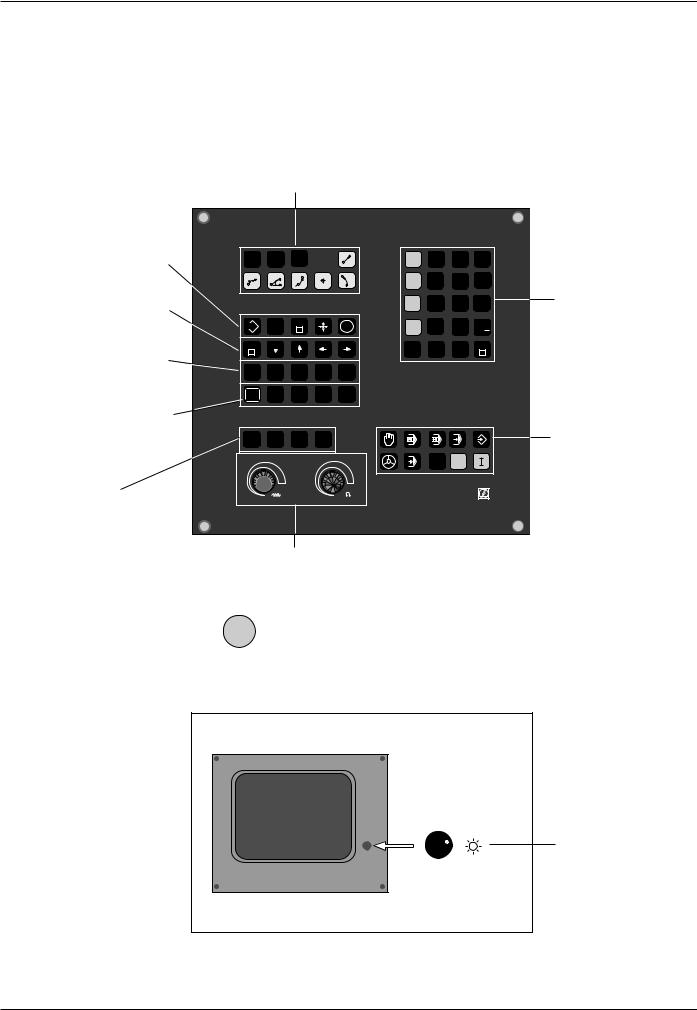
The Operating Panel
The keys on the TNC operating panel are grouped according to their functions:
• Program selection
• Address letters
•External data transfer
•Probing functions
•Editing functions
•Jump instruction GOTO
•Arrow keys
•Address letters
•NO ENT key
•Tool-related address letters
Graphic operating modes
PGM |
CL |
PGM |
|
|
L |
X |
7 |
8 |
9 |
NR |
PGM |
CALL |
|
|
|
||||
CR |
RND |
CT |
|
CC |
C |
Y |
4 |
5 |
6 |
|
|
|
|
|
|
||||
|
|
|
|
|
|
Z |
1 |
2 |
3 |
EXT |
TOUCH |
DEL |
|
|
ENT |
IV |
0 |
. |
+/ |
PROBE |
|
|
|
||||||
|
|
|
|
|
|||||
GOTO |
|
|
|
|
|
CE |
Q |
Q |
END |
|
|
|
|
|
|
DEF |
|
||
STOP |
CYCL |
CYCL |
|
LBL |
LBL |
|
|
|
|
DEF |
CALL |
|
SET |
CALL |
|
|
|
|
|
|
|
|
|
|
|
||||
NO |
TOOL |
TOOL |
|
L |
R |
|
|
|
|
ENT |
DEF |
CALL |
|
R- |
R+ |
|
|
|
|
|
GRAPHICS |
|
|
|
|
|
|
|
|
MOD |
BLK |
MAGN |
|
START |
|
|
|
|
|
FORM |
|
|
|
|
|
|
|||
|
|
|
|
|
|
|
|
|
|
|
100 |
|
|
100 |
|
|
MOD |
P |
|
|
|
|
|
|
|
|
|
||
|
|
|
|
|
|
|
|
|
|
50 |
|
150 |
50 |
|
150 |
|
|
|
|
|
0 |
F % |
|
0 |
S % |
|
HEIDENHAIN |
||
|
|
|
|
|
|
|
|
||
•Numerical entries
•Axis selection
Operating modes
Override controls |
The functions of the individual keys are de- |
for spindle speed |
|
and feed rate |
scribed on the inside front cover. An overview |
|
of the address letters used for ISO program- |
|
ming is provided in Chapter 11. |
The machine operating buttons, such as |
I for NC start, are described in the manual for your machine tool. |
In this manual they are shown in gray.
The Screen
Brightness control (BE 212 only)
Header
The header of the screen shows the selected operating mode. Dialog questions and TNC messages also appear there.
TNC 360 |
1-3 |
1 Introduction
1.1The TNC 360
Screen Layout
MANUAL and EL. HANDWHEEL operating modes:
A machine operating mode has been selected
•Coordinates
•Selected axis
•means: control is in operation
•Status display, e.g. feed rate F, miscellaneous function M
A program run operating mode has been selected
Section of selected program
Status display
The screen layout is the same in the operating modes PROGRAM RUN, PROGRAMMING AND EDITING and TEST RUN. The current block is shown between two horizontal lines.
1-4 |
TNC 360 |

1 Introduction
1.1The TNC 360
TNC Accessories
3D Touch Probe Systems
The TNC features the following functions for the
HEIDENHAIN 3D touch probe systems:
•Automatic workpiece alignment (compensation of workpiece misalignment)
•Datum setting
•Measurements of the workpiece can be performed during program run
•Digitizing 3D forms (optional, only available with HEIDENHAIN plain language dialog programming)
The TS 120 touch probe system is connected to the control via cable, while the TS 510 communicates by means of infrared light.
Fig. 1.5: HEIDENHAIN 3D Touch Probe Systems TS 120 and TS 511
Floppy Disk Unit
The HEIDENHAIN FE 401 floppy disk unit serves as an external memory for the TNC, allowing you to store your programs externally on diskette.
The FE 401 can also be used to transfer programs that were written on a PC into the TNC. Extremely long programs which exceed the TNC's memory capacity are “drip fed” block by block. The machine executes the transferred blocks and erases them immediately, freeing memory for further blocks from the FE.
Fig. 1.6: HEIDENHAIN FE 401 Floppy Disk Unit
Electronic Handwheels
Electronic handwheels provide precise manual control of the axis slides. As on conventional machines, turning the handwheel moves the axis by a defined amount. The traverse distance per revolution of the handwheel can be adjusted over a wide range.
Portable handwheels, such as the HR 330, are connected to the TNC by cable. Built-in handwheels, such as the HR 130, are built into the machine operating panel.
An adapter allows up to three handwheels to be connected simultaneously. Your machine tool
builder can tell you more about the handwheel Fig. 1.7: The HR 330 Electronic Handwheel configuration of your machine.
TNC 360 |
1-5 |

1 Introduction
1.2 Fundamentals of Numerical Control (NC)
Introduction
This chapter addresses the following topics:
•What is NC?
•The part program
•Programming
•Reference system
•Cartesian coordinate system
•Additional axes
•Polar coordinates
•Setting the pole
•Datum setting
•Absolute workpiece positions
•Incremental workpiece positions
•Programming tool movements
•Position encoders
•Reference mark evaluation
What is NC?
NC stands for Numerical Control. Simply put, numerical control is the operation of a machine by means of coded instructions. Modern controls such as the HEIDENHAIN TNCs have a built-in computer for this purpose. Such a control is therefore also called a CNC (Computer Numerical Control).
The part program
A part program is a complete list of instructions for machining a workpiece. It contains such information as the target position of a tool movement, the tool path — i.e. how the tool should move towards the target position — and the feed rate. The program must also contain information on the radius and length of the tools, the spindle speed and the tool axis.
Programming
The TNC is programmed in the ISO format; some programming sections, however, are guided by dialog prompting. The single commands (words) can be entered in any sequence within a block (except G90/G91). The TNC automatically sorts the single commands as soon as the block is concluded.
1-6 |
TNC 360 |

1 Introduction
1.2Fundamentals of NC
Reference system
In order to define positions one needs a reference system. For example, positions on the earth's surface can be defined "absolutely" by their geographic coordinates of longitude and latitude. The term "coordinate" comes from the Latin word for "that which is arranged", i.e. dimensions used for determining or defining positions. The network of horizontal and vertical lines around the globe constitutes an "absolute reference system"
– in contrast to the "relative" definition of a position that is referenced, for example, to some other, known location.
60°
Greenwich
30°
0°
30°
60°
90° 0° 90°
Fig. 1.8: The geographic coordinate system is an absolute reference system
Cartesian coordinate system
On a TNC controlled milling machine a workpiece is normally machined according to a workpiece-referenced Cartesian coordinate system (a rectangular coordinate system named after the French mathematician and philosopher René Descartes, Latin: Renatus Cartesius; 1596 to 1650). The Cartesian coordinate system is based on three coordinate axes X, Y and Z, which are parallel to the machine guideways. The figure to the right illustrates the "right hand rule" for remembering the three axis directions: the middle finger is pointing in the positive direction of the tool axis from the workpiece toward the tool (the Z axis), the thumb is pointing in the positive X direction, and the index finger in the positive Y direction.
+Y |
+Z |
+X |
|
|
+X |
Fig. 1.9: Designations and directions of the axes on a milling machine
TNC 360 |
1-7 |
1 Introduction
1.2Fundamentals of NC
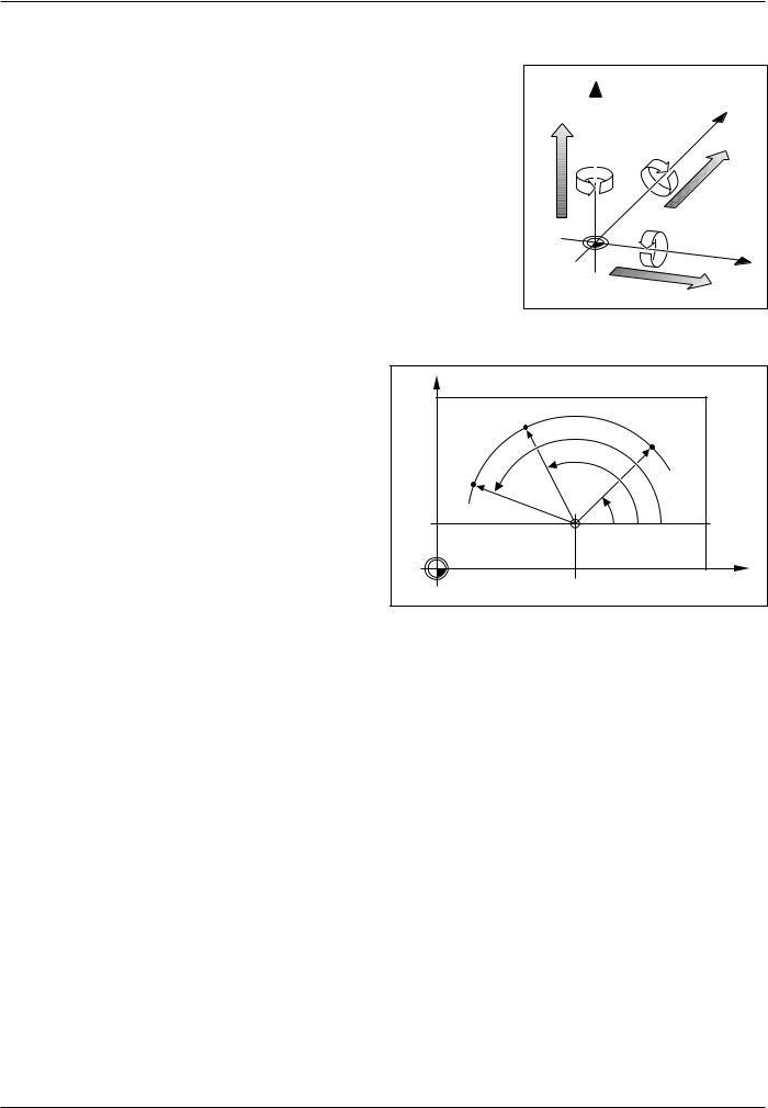
Additional axes
The TNC can control machines that have more than three axes. U, V and W are secondary linear axes parallel to the main axes X, Y and Z, respectively (see illustration). Rotary axes are also possible. They are designated as axes A, B and C.
|
Z |
Y |
|
|
|
W+ |
C+ |
B+ |
|
||
|
|
V+ |
|
|
A+ |
|
|
X |
|
|
U+ |
Fig. 1.10: Arrangement and designation of the auxiliary axes
Polar coordinates |
Y |
|
|
The Cartesian coordinate system is especially |
|
|
|
|
|
|
|
useful for parts whose dimensions are mutually |
|
|
|
perpendicular. But when workpieces contain |
|
R |
|
circular arcs, or when dimensions are given in |
|
|
|
|
R |
|
|
degrees, it is often easier to use polar coordinates. |
|
|
|
|
H 2 |
|
|
In contrast to Cartesian coordinates, which are |
|
H 3 |
|
three-dimensional, polar coordinates can only |
|
|
|
describe positions in a plane. |
|
R |
|
|
J = 10 |
H 1 |
0° |
The datum for polar coordinates is the pole I, J, K. |
|
||
|
|
|
|
To describe a position in polar coordinates, think of |
|
|
|
a scale whose zero point is rigidly connected to the |
|
|
|
pole but which can be freely rotated in a plane |
|
|
X |
around the pole. |
|
I = 30 |
|
Positions in this plane are defined by: |
Fig. 1.11: |
Positions on an arc with polar coordinates |
|
•Polar Radius R: The distance from the pole I, J to the defined position.
•Polar Angle H: The angle between the reference axis and the scale.
1-8 |
TNC 360 |
1 Introduction
1.2Fundamentals of NC
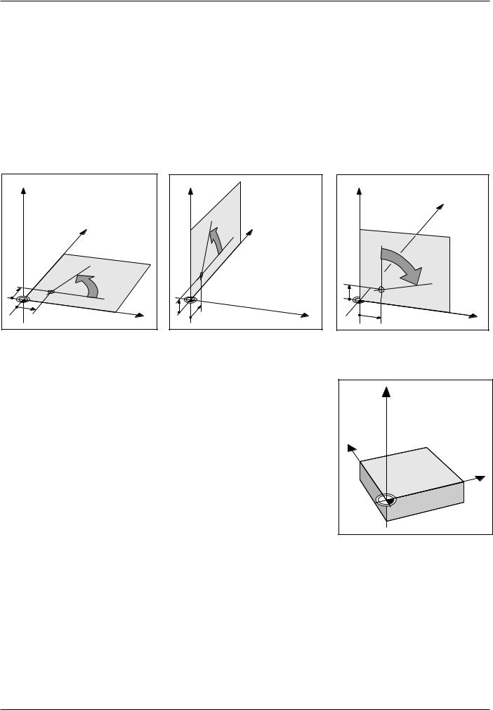
Setting the pole
The pole is defined by setting two Cartesian coordinates. These two coordinates also determine the reference axis for the polar angle PA.
Coordinates of the pole |
Reference axis of the angle |
|
|
I, J |
+X |
J, K |
+Y |
K, I |
+Z |
|
|
Z |
|
|
|
Y |
|
J |
+ |
|
0° |
||
|
||
I |
X |
|
|
|
Z |
|
|
|
|
|
|
+ |
|
° |
Y |
|
|
0 |
|
||
|
|
|
|
||
|
|
|
|
|
|
K |
J |
|
|
|
X |
|
|
|
|
Fig. 1.12: Polar coordinates and their associated reference axes
Setting the datum
The workpiece drawing identifies a certain prominent point on the workpiece (usually a corner) as the "absolute datum" and perhaps one or more other points as relative datums. The process of datum setting establishes these points as the origin of the absolute or relative coordinate systems:
The workpiece, which is aligned with the machine axes, is moved to a certain position relative to the tool and the display is set either to zero or to another appropriate position value (e.g. to compensate the tool radius).
Z |
|
Y |
|
|
|
|
|
0° |
|
|
+ |
K |
|
|
|
I |
X |
|
|
Z |
Y |
X |
Fig. 1.13: The workpiece datum serves as the origin of the Cartesian coordinate system
TNC 360 |
1-9 |

1 Introduction
1.2Fundamentals of NC
Example:
Drawings with several relative datums
(according to ISO 129 or DIN 406, Part 11; Figure 171)
|
|
-250 |
-216,5 |
-125 |
0 |
125 |
216,5 |
250 |
|
|
|
|
|
|
|
|
|
216,5 |
250 |
|
|
|
|
|
|
|
|
|
|
|
|
|
|
|
|
|
|
125 |
|
1225 |
|
|
|
|
|
|
|
0 |
|
|
|
|
|
|
|
|
|
-125 |
|
|
150 |
|
|
|
|
|
|
-216,5 |
-250 |
|
|
|
|
|
|
|
|
|
|
750 |
0 |
|
|
|
|
|
|
|
|
|
|
|
|
|
|
|
|
|
|
300±0,1 |
-150 |
|
|
|
|
|
|
|
|
|
0 |
|
|
|
|
|
|
|
|
320 |
|
|
|
|
|
|
|
|
|
0 |
|
|
|
|
|
|
|
|
|
0 |
325 |
450 |
|
700 |
|
900 950 |
|
||
Example: |
|
|
|
|
|
|
|
|
|
Coordinates of the point :
X = 10 mm
Y = 5 mm
Z = 0 mm
The datum of the Cartesian coordinate system is located 10 mm away from point on the X axis and 5 mm on the Y axis.
The 3D Touch Probe System from HEIDENHAIN is an especially convenient and efficient way to find and set datums.
Z |
Y |
X |
1 |
5 |
10 |
Fig. 1.15: Point defines the coordinate system.
1-10 |
TNC 360 |
1 Introduction
1.2Fundamentals of NC
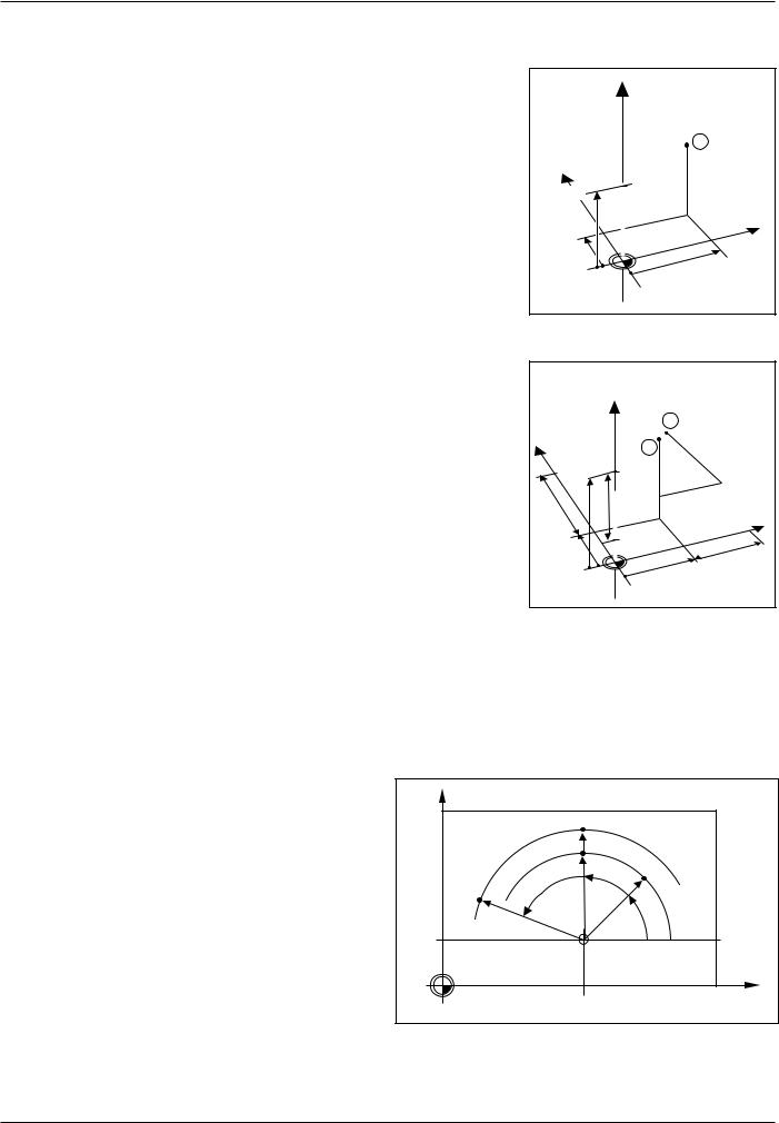
Absolute workpiece positions
Each position on the workpiece is clearly defined by its absolute coordinates.
Example: Absolute coordinates of the position :
X = 20 mm
Y = 10 mm
Z = 15 mm
If you are drilling or milling a workpiece according to a workpiece drawing with absolute coordinates, you are moving the tool to the coordinates.
Incremental workpiece positions
A position can be referenced to the previous nominal position: i.e. the relative datum is always the last programmed position. Such coordinates are referred to as incremental coordinates (increment = growth), or also incremental or chain dimensions (since the positions are defined as a chain of dimensions). Incremental coordinates are designated with G91.
Example: Incremental coordinates of the position referenced to position
Absolute coordinates of the position :
X = 10 mm
Y = 5 mm
Z = 20 mm
Incremental coordinates of the position :
IX = 10 mm
IY = 10 mm
IZ = –15 mm
If you are drilling or milling a workpiece according to a workpiece drawing with incremental coordinates, you are moving the tool by the coordinates.
An incremental position definition is therefore intended as an immediately relative definition. This is also the case when a position is defined by the distance-to-go to the target position (here the relative datum is located at the target position). The distance-to-go has a negative algebraic sign if the target position lies in the negative axis direction from the actual position.
|
Z |
|
|
|
|
|
|
1 |
|
Y |
|
|
|
|
15 |
|
Z=15mm |
|
|
|
|
Y=10mm |
X |
|
|
X=20mm |
|
||
|
|
|
||
|
|
|
|
|
10 |
|
|
|
|
|
|
|
|
20 |
Fig. 1.16: Position of the example "absolute workpiece positions"
|
Z |
3 |
|
|
|
||
Y |
|
|
I |
|
15mm–Z=I |
Y |
|
2 |
= |
||
1 |
|||
|
0 |
||
|
|
m |
|
|
|
m |
|
20 |
|
IX=10mm |
|
|
|
|
|
10 |
15 |
|
X |
|
|
||
|
|
|
|
5 |
5 |
|
10 |
|
|
|
|
0 |
|
|
10 |
|
|
|
|
|
0 |
|
|
Fig. 1.17: Positions and of the example "incremental workpiece positions"
The polar coordinate system can also express both types of dimensions:
•Absolute polar coordinates always refer to the pole I, J and the angle reference axis.
•Incremental polar coordinates always refer to the last programmed nominal position of the tool.
Y |
|
|
G91R |
|
|
R |
|
|
G91H |
G91H |
R |
|
|
|
R |
|
H |
|
|
|
J = 10 |
|
0° |
I = 30 |
X |
|
Fig. 1.18: Incremental dimensions in polar coordinates (designated with "G91")
TNC 360 |
1-11 |
1 Introduction
1.2Fundamentals of NC
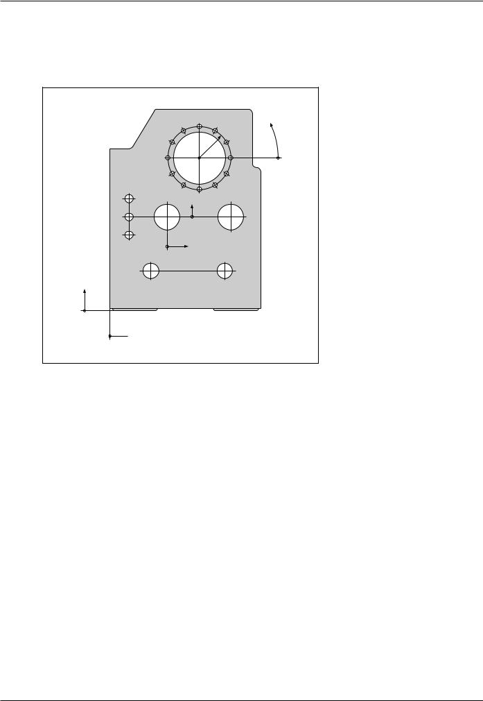
Example:
Workpiece drawing with coordinate dimensioning (according to ISO 129 or DIN 406, Part 11; Figure 179)
|
3.5 |
3.4 |
3.3 |
|
|
|
|
||
|
3.6 |
r |
3.2 |
ϕ |
|
|
3.1 |
|
|
|
3.7 |
|
|
|
|
3 |
|
|
|
|
|
|
|
|
|
3.8 |
|
3.12 |
|
2.1 |
3.9 |
3.10 |
3.11 |
|
|
|
|
|
|
2.2 |
2 |
Y2 |
1.3 |
|
|
|
|||
2.3 |
|
|
|
|
|
|
X2 |
|
|
|
1.1 |
|
1.2 |
|
Y1
1
 X1
X1
|
|
|
|
|
|
Dimensions in mm |
|
|
|
|||
|
|
|
|
|
|
|
|
|
|
|
|
|
Coordinate |
|
|
|
Coordinates |
|
|
|
|
|
|
||
origin |
Pos. |
X1 X2 |
|
Y1 Y2 |
|
r |
|
ϕ |
|
|
d |
|
|
|
|
|
|
|
|||||||
|
|
|
|
|
|
|
||||||
|
|
|
|
|
|
|
|
|
|
|
|
|
1 |
1 |
0 |
|
0 |
|
|
|
|
|
|
- |
|
1 |
1.1 |
325 |
|
320 |
|
|
|
|
|
Ø |
120 |
H7 |
1 |
1.2 |
900 |
|
320 |
|
|
|
|
|
Ø |
120 |
H7 |
1 |
1.3 |
950 |
|
750 |
|
|
|
|
|
Ø |
200 |
H7 |
1 |
2 |
450 |
|
750 |
|
|
|
|
|
Ø |
200 |
H7 |
1 |
3 |
700 |
|
1225 |
|
|
|
|
|
Ø |
400 |
H8 |
2 |
2.1 |
–300 |
|
150 |
|
|
|
|
|
Ø |
50 |
H11 |
2 |
2.2 |
–300 |
|
0 |
|
|
|
|
|
Ø |
50 |
H11 |
2 |
2.3 |
–300 |
|
–150 |
|
|
|
|
|
Ø |
50 |
H11 |
3 |
3.1 |
|
|
|
|
250 |
|
0° |
|
Ø |
26 |
|
3 |
3.2 |
|
|
|
|
250 |
|
30° |
|
Ø |
26 |
|
3 |
3.3 |
|
|
|
|
250 |
|
60° |
|
Ø |
26 |
|
3 |
3.4 |
|
|
|
|
250 |
|
90° |
|
Ø |
26 |
|
3 |
3.5 |
|
|
|
|
250 |
|
120° |
|
Ø |
26 |
|
3 |
3.6 |
|
|
|
|
250 |
|
150° |
|
Ø |
26 |
|
3 |
3.7 |
|
|
|
|
250 |
|
180° |
|
Ø |
26 |
|
3 |
3.8 |
|
|
|
|
250 |
|
210° |
|
Ø |
26 |
|
3 |
3.9 |
|
|
|
|
250 |
|
240° |
|
Ø |
26 |
|
3 |
3.10 |
|
|
|
|
250 |
|
270° |
|
Ø |
26 |
|
3 |
3.11 |
|
|
|
|
250 |
|
300° |
|
Ø |
26 |
|
3 |
3.12 |
|
|
|
|
250 |
|
330° |
|
Ø |
26 |
|
|
|
|
|
|
|
|
|
|
|
|
|
|
1-12 |
TNC 360 |

1 Introduction
1.2Fundamentals of NC
Programming tool movements
An axis position is changed either by moving the tool or by moving the machine table on which the workpiece is fixed, depending on the individual machine tool.
You always program as if the tool is moving and the workpiece is stationary.
If the machine table moves in one or several axes, the corresponding axes are designated on the machine operating panel with a prime mark (e.g. X’, Y’). When an axis is designated with a prime mark, the programmed direction of axis movement is the opposite direction of tool movement relative to the workpiece.
Position encoders
The position encoders – linear encoders for linear axes, angle encoders for rotary axes – convert the movement of the machine axes into electrical signals. The control evaluates these signals and constantly calculates the actual position of the machine axes.
If there is an interruption in power, the calculated position will no longer correspond to the actual position. When power is returned, the TNC can re-establish this relationship.
+Y |
+Z |
+X |
Fig. 1.20: On this machine the tool moves in the Y and Z axes; the machine table moves in the positive X' axis direction.
Z |
Y |
X |
Fig. 1.21: Linear position encoder, here for the X axis
Reference marks
The scales of the position encoders contain one or more reference marks. When a reference mark is passed over, it generates a signal which identifies that position as the machine axis reference point.
With the aid of these reference marks the TNC can re-establish the assignment of displayed positions to machine axis positions.
If the position encoders feature distance-coded reference marks, each axis need only move a maximum of 20 mm (0.8 in.) for linear encoders, and 20° for angle encoders.
Fig. 1.22: Linear scales: above with distance-coded-reference marks, below with one reference mark
TNC 360 |
1-13 |
 Loading...