


Operating Instructions
ND 1400 QUADRA-CHEK
(QC 330)
English (en) 2/2010
QC-330 Series
User’s Guide
Touch Probe Systems
QC-330 and QC-331
QC-330 Series Touch Probe Systems
User’s Guide
Published by Metronics, Inc. 30 Harvey Road
Bedford, New Hampshire 03110 www.metronics.com
User’s Guide part number: |
11A10609 Revision 0 |
Publishing date: |
June, 2008 |
Printed in United States of America |
|
Copyright © 2008 by Metronics, Inc., Bedford, New Hampshire
QC-330 software version: 1.40
All information set forth in this document, all rights to such information, any and all inventions disclosed herein and any patents that might be granted by employing the materials, methods, techniques or apparatus described herein are the exclusive property of Metronics Inc., Bedford, New Hampshire.
Terms, conditions and features referenced in this document are subject to change without notice.
No part of this document may be reproduced, stored in a retrieval system, or transmitted in any form or by any means, electronic, mechanical, photocopying, recording, or otherwise, without prior written permission of Metronics, Inc.. Requests to Metronics, Inc. for permission should be addressed to the Technical Services Department, Metronics, Inc., 30 Harvey Road, Bedford, New Hampshire 03110.
Limit of liability and disclaimer of warranty
While this guide was prepared with great care, Metronics makes no representations or warranties with respect to the accuracy or completeness of the contents of this book and specifically disclaims any implied warranties of merchantability or fitness for a particular purpose. The advice, methods and instructions contained in this book might not be suitable for your situation. When in doubt regarding suitability, you are encouraged to consult with a professional where appropriate. Metronics shall not be liable for any loss of profit or any damages, including but not limited to special, incidental, consequential or other damages.
Trademarks
Metronics, Quadra-Chek and QC-330 are registered trademarks of Metronics, Inc. and its subsidiaries in the United States and other countries. Other product names used in this document are for identification purposes only and may be trademarks of their respective owners. Metronics Incorporated disclaims any and all rights to those marks.

Conventions & Terms
QC-330 refers to any of the QC-330 series of instruments. System refers to the QC-330 and the measuring devices connected to it.
Icons
This guide uses the following icons to highlight information:
WARNINGS
The raised hand icon warns of a situation or condition that can lead to personal injury or death. Do not proceed until the warning is read and thoroughly understood.
DANGEROUS VOLTAGE
The lightning icon warns of the presence of a dangerous voltage within the product enclosure that might be of sufficient magnitude to cause serious shocks or death. Do not open the enclosure unless you are a qualified service person approved by Metronics, Inc., and never open the enclosure while power is connected.
CAUTIONS & IMPORTANT INFORMATION
The exclamation point icon indicates important information regarding equipment operation or maintenance, or a situation or condition that can lead to equipment malfunction or damage. Do not proceed until the information is read and thoroughly understood.
NOTE
The note icon indicates additional or supplementary information about an activity or concept.
Safety & Maintenance Considerations
General safety precautions must be followed when operating the system. Failure to observe these precautions could result in damage to the equipment, or injury to personnel.
It is understood that safety rules within individual companies vary. If a conflict exists between the material contained in this guide and the rules of a company using this system, the more stringent rules should take precedence.
Additional safety information is included on the next page and in Chapter 2: Installation.

WARNINGS
Disconnect the QC-330 from power before cleaning.
The QC-330 is equipped with a 3-wire power plug that includes a separate ground connection. Always connect the power plug to a 3-wire grounded outlet. The use of accessories that remove the third grounded connection such as a 2-wire power plug adapter create
a safety hazard and should not be permitted. If a 3-wire grounded outlet is not available, ask your electrician to provide one.
DANGEROUS VOLTAGE
Do not open the enclosure unless you are a qualified service person approved by Metronics, Inc., and never open the enclosure while power is connected. There are no user-serviceable components or assemblies inside. Refer servicing to qualified service personnel.
General Maintenance
Disconnect the QC-330 from power and seek the assistance of a qualified service technician if:
•The power cord is frayed or damaged or the power plug is damaged
•Liquid is spilled or splashed onto the enclosure
•The QC-330 has been dropped or the exterior has been damaged
•The QC-330 exhibits degraded performance or indicates a need for service some other way
Cleaning the enclosure
Use only a cloth dampened with water and a mild detergent for cleaning the exterior surfaces. Never use abrasive cleaners, and never use strong detergents or solvents. Only dampen the cloth, do not use a cleaning cloth that is dripping wet. Instructions for cleaning the touch screen are different and are given below.
Cleaning the touch screen
The touch screen should be cleaned as described below to prevent scratching or wearing the screen surface and to prevent liquids from leaking into the enclosure.
Use only a soft, lint-free cloth dampened with water for cleaning the touch screen. Never use abrasive cloths or paper towels. Never use abrasive cleaners, and never use detergents or solvents. Only dampen the cloth, do not use a cleaning cloth that is dripping wet. Never spray the screen.
If the screen is badly soiled, the cloth can be dampened with a 50:50 mixture of isopropyl alcohol and water. Remember, only dampen the cloth, do not use a cleaning cloth that is dripping wet, and never spray the screen.
Contents |
|
|
Chapter 1 |
Overview |
|
|
Overview of the QC-330 features and functions................................ |
1 |
Chapter 2 |
Installation |
|
|
Unpacking the QC-330....................................................................... |
5 |
|
Assembling the mounting stand......................................................... |
6 |
|
Safety considerations.......................................................................... |
6 |
|
Power cord and plug.................................................................... |
6 |
|
Electrical wiring and connections .............................................. |
6 |
|
Location and mounting............................................................... |
7 |
|
Power surge suppressor............................................................... |
7 |
|
Connecting axis encoders................................................................... |
7 |
|
Connecting the touch probe input...................................................... |
8 |
|
Connecting a printer........................................................................... |
8 |
|
Connecting a computer....................................................................... |
9 |
|
Connecting an optional footswitch..................................................... |
9 |
|
Warranty registration form ................................................................ |
10 |
|
Repackaging for shipment.................................................................. |
10 |
Chapter 3 |
User Interface |
|
|
LCD Screen functions........................................................................ |
12 |
|
Data display ....................................................................................... |
13 |
|
DRO screen................................................................................. |
13 |
|
View screen................................................................................. |
14 |
|
TOL screen.................................................................................. |
15 |
|
Measurement functions...................................................................... |
16 |
|
Selecting a measurement type..................................................... |
16 |
|
Accessing programs.................................................................... |
17 |
|
Sending data to a computer from the Extra tab........................... |
18 |
|
Extra tab functions...................................................................... |
19 |
|
Space menu insert................................................................ |
19 |
|
Divider line menu insert....................................................... |
19 |
|
Transmit feature data........................................................... |
19 |
|
Data prompt function .......................................................... |
19 |
Contents
QC-300 Series User’s Guide |
|
Rotate about axis function................................................... |
19 |
Multiple Extra tabs ..................................................................... |
19 |
Feature list ......................................................................................... |
20 |
System functions................................................................................ |
21 |
Undo............................................................................................ |
21 |
Probe. holder............................................................................... |
21 |
Reference frame.......................................................................... |
21 |
Projection.................................................................................... |
22 |
Unit of measure........................................................................... |
22 |
Setup............................................................................................ |
22 |
Command buttons and wide keys....................................................... |
23 |
Number keys...................................................................................... |
24 |
LCD ON/OFF and deleting feature data............................................ |
25 |
Printing reports and sending data....................................................... |
26 |
Chapter 4 |
Quick Start Demonstration |
|
|
Start recording a program................................................................... |
28 |
|
Establish a reference frame................................................................ |
28 |
|
Measure a feature............................................................................... |
30 |
|
Apply tolerances to a feature measurement....................................... |
30 |
|
Print a report....................................................................................... |
31 |
|
Stop program recording ..................................................................... |
31 |
|
Run the program................................................................................. |
31 |
Chapter 5 |
Probes |
|
|
Probe qualification............................................................................. |
33 |
|
Probing technique............................................................................... |
35 |
|
Auto change/teach function................................................................ |
35 |
QC-300 Series User’s Guide
Chapter 6 |
Measuring |
Contents
Measurement activities....................................................................... |
38 |
The measurement process.................................................................. |
38 |
Establishing a reference frame........................................................... |
39 |
Part leveling................................................................................ |
39 |
Part skew alignment.................................................................... |
40 |
Establishing a datum zero point.................................................. |
41 |
Saving the reference frame.......................................................... |
43 |
Saving reference frames manually....................................... |
43 |
Saving reference frames automatically................................ |
44 |
Measuring features............................................................................. |
45 |
Selecting a projection plane........................................................ |
45 |
Probing features.......................................................................... |
46 |
Probing with Measure Magic............................................... |
46 |
Probing without Measure Magic.......................................... |
47 |
Probing a single specific feature type........................... |
47 |
Probing multiple specific feature types........................ |
47 |
Probing process.................................................................... |
48 |
Supported feature types........................................................ |
48 |
Backward/forward annotation.............................................. |
49 |
Probing specific feature types.............................................. |
50 |
Probing points............................................................... |
50 |
Probing lines ................................................................ |
51 |
Probing circles.............................................................. |
52 |
Probing arcs.................................................................. |
53 |
Probing angles.............................................................. |
55 |
Probing distances.......................................................... |
56 |
Probing planes.............................................................. |
57 |
Probing cylinders.......................................................... |
58 |
Probing cones................................................................ |
59 |
Probing spheres............................................................. |
60 |
Constructing features.......................................................................... |
61 |
Duplicate features........................................................................ |
61 |
Extracted features........................................................................ |
62 |
Intersection features.................................................................... |
62 |
Relation features.......................................................................... |
63 |
Multipoint features ..................................................................... |
63 |
Perpendicular/parallel/tangent features....................................... |
64 |
Gage line and circle features....................................................... |
65 |
Creating features................................................................................. |
66 |
Contents |
QC-300 Series User’s Guide |
|
Chapter 7 |
Tolerances |
|
|
Applying tolerances to features ............................................................ |
69 |
|
Select a feature from the feature list.............................................. |
69 |
|
Select the desired fit algorithm...................................................... |
69 |
|
Display the TOL screen................................................................. |
69 |
|
Select a tolerance............................................................................ |
70 |
|
Position tolerances.................................................................. |
71 |
|
Form tolerances....................................................................... |
71 |
|
Orientation tolerances............................................................. |
72 |
|
Runout tolerances.................................................................... |
72 |
|
Size tolerances........................................................................ |
72 |
|
Enter nominal, limit or tolerance values........................................ |
73 |
|
Omitting a tolerance category........................................................ |
73 |
|
Tolerance types...................................................................................... |
74 |
|
Position/Bidirectional..................................................................... |
74 |
|
Points....................................................................................... |
74 |
|
Lines........................................................................................ |
74 |
|
Circles, arcs and spheres ........................................................ |
75 |
|
Slots and rectangles................................................................ |
75 |
|
Position/True position ................................................................... |
76 |
|
Points and lines....................................................................... |
76 |
|
Circles, arcs, spheres and cylinders........................................ |
76 |
|
Position/MMC and LMC (Material conditions)............................ |
77 |
|
MMC Circles, arcs and cylinders........................................... |
77 |
|
LMC Circles, arcs and cylinders............................................. |
78 |
|
Position/Concentricity circles and arcs.......................................... |
79 |
|
Form/Straightness lines.................................................................. |
79 |
|
Form/Roundness circles, arcs and spheres .................................... |
79 |
|
Form/Cylindricity cylinders........................................................... |
80 |
|
Form/Flatness planes...................................................................... |
80 |
|
Orientation/Perpendicularity lines, cylinders, cones, planes......... |
80 |
|
Orientation/Parallelism lines, cylinders, cones.............................. |
80 |
|
Orientation/Angle angles, cones.................................................... |
81 |
|
Orientation/Co-planarity planes..................................................... |
81 |
|
Runout/Circular runout circles, arcs.............................................. |
81 |
|
Size/Width distances...................................................................... |
82 |
|
Size/Radius, diameter, length, width.............................................. |
82 |
QC-300 Series User’s Guide
Chapter 8 |
Programming |
Contents
|
Creating programs................................................................................. |
83 |
|
Start program recording................................................................. |
84 |
|
Enter a program title (or user message)......................................... |
85 |
|
Create a reference frame for measurements................................... |
86 |
|
Measure a feature (include a message).......................................... |
86 |
|
Apply a tolerance........................................................................... |
87 |
|
Report results................................................................................. |
87 |
|
Stop the program recording................................................................... |
88 |
|
Editing Programs .................................................................................. |
89 |
|
Editing existing steps..................................................................... |
89 |
|
Editing program settings................................................................ |
89 |
|
Editing tolerances........................................................................... |
90 |
|
Editing user prompt messages........................................................ |
91 |
|
Inserting or appending new program steps.................................... |
92 |
|
Running programs................................................................................. |
93 |
|
Saving and retrieving programs............................................................ |
94 |
|
Saving programs............................................................................. |
94 |
|
Retrieving programs....................................................................... |
94 |
|
Deleting programs................................................................................. |
96 |
Chapter 9 |
Communications |
|
|
Connecting to a computer...................................................................... |
97 |
|
Sending data to a computer................................................................... |
98 |
|
Sending data to a printer........................................................................ |
99 |
|
Printer format strings...................................................................... |
99 |
|
Report formats ............................................................................... |
99 |
|
Printing a report..................................................................................... |
100 |
|
Printing feature measurement data................................................. |
100 |
|
Printing QC-330 system settings.................................................... |
101 |
|
RS-232 connector pin designations ...................................................... |
102 |
|
ASCII Code table.................................................................................. |
102 |
Contents |
QC-300 Series User’s Guide |
|
Chapter 10 |
Setup |
|
|
The Setup Menu.................................................................................... |
104 |
|
Accessing and using the Setup Menu............................................. |
104 |
|
Entering the supervisor password........................................... |
105 |
|
Selecting items from the Setup Menu .................................... |
106 |
|
Selecting setup parameter choices.......................................... |
106 |
|
Entering and deleting setup data............................................. |
106 |
|
Storing a parameter and advancing to the next step............... |
107 |
|
Leaving the setup menu.......................................................... |
107 |
|
Minimum setup...................................................................................... |
108 |
|
Setup screen descriptions...................................................................... |
109 |
|
Language screen............................................................................. |
109 |
|
Specifying the displayed language ......................................... |
109 |
|
Supervisor screen........................................................................... |
110 |
|
Entering the supervisor password........................................... |
110 |
|
Keeping setup privileges until the power is cycled................ |
110 |
|
Hiding setup parameters from unauthorized personnel.......... |
110 |
|
Limiting access to program functions .................................... |
110 |
|
Saving and loading settings.................................................... |
111 |
|
Encoders screen.............................................................................. |
112 |
|
Selecting an axis to configure................................................. |
112 |
|
Specifying encoder resolution................................................. |
112 |
|
Specifying encoder type.......................................................... |
112 |
|
Calibrating analog encoders.................................................... |
113 |
|
Selecting reference marks ...................................................... |
115 |
|
None................................................................................. |
115 |
|
Manual............................................................................. |
115 |
|
Single............................................................................... |
115 |
|
Absolute........................................................................... |
115 |
|
Setting a new machine zero reference.................................... |
116 |
|
Reversing the encoder count direction.................................... |
116 |
|
Enabling axis error messages.................................................. |
116 |
|
Specifying slew limit.............................................................. |
116 |
|
Squareness screen........................................................................... |
117 |
|
Calibrating system squareness................................................ |
117 |
|
SLEC screen .................................................................................. |
118 |
|
LEC or SLEC, which is right for my application?................. |
118 |
|
LEC (Linear error correction)................................................. |
118 |
|
SLEC (Segmented linear error correction) ............................ |
120 |
QC-300 Series User’s Guide |
Contents |
|
Probe screen................................................................................... |
|
123 |
Probe holder............................................................................ |
|
123 |
Hard probe.............................................................................. |
|
123 |
Probe active level is high........................................................ |
|
123 |
Debounce time........................................................................ |
|
123 |
Probe to probe delay............................................................... |
|
124 |
Direction threshold.................................................................. |
|
124 |
Qualification diameter............................................................ |
|
124 |
Qualify at startup..................................................................... |
|
124 |
Allow auto change/teach......................................................... |
|
124 |
Auto change/teach distance..................................................... |
|
124 |
Find qual sphere at startup...................................................... |
|
125 |
Stack length............................................................................. |
|
125 |
Measure screen .............................................................................. |
|
127 |
Annotation............................................................................... |
|
127 |
Minimum points required for a feature measurement............. |
127 |
|
Probe hit starts measure magic............................................... |
|
128 |
Auto save UCS (User Coordinate System) ............................ |
|
128 |
Distances................................................................................. |
|
128 |
Enabling and configuring point filtration............................... |
|
128 |
Enabling point filtration................................................... |
|
129 |
Specifying a filtration error limit .................................... |
|
129 |
Specifying a filtration standard deviation range |
............. |
129 |
Specifying the min percentage of retained points............ |
129 |
|
Display screen ............................................................................... |
|
130 |
Display resolution................................................................... |
|
130 |
Default units of linear measure .............................................. |
|
131 |
Radix for numeric displays .................................................... |
|
131 |
Angular units of measure........................................................ |
|
131 |
Time formats........................................................................... |
|
131 |
Date formats............................................................................ |
|
131 |
Display mode switching.......................................................... |
|
132 |
Configuring the Extra tab........................................................ |
|
133 |
Extra tab functions........................................................... |
|
134 |
Space menu insert............................................................ |
|
134 |
Divider line menu insert.................................................. |
|
134 |
Data prompt function ...................................................... |
|
134 |
Axis position ................................................................... |
|
134 |
Angle............................................................................... |
|
134 |
Diameter.......................................................................... |
|
134 |
Rotate coordinate system................................................. |
|
134 |
Contents
QC-300 Series User’s Guide |
|
Header screen..................................................................................... |
135 |
Creating report headers............................................................... |
135 |
Print screen......................................................................................... |
136 |
Specifying a data type ................................................................ |
136 |
Specifying a data destination...................................................... |
136 |
Report Type................................................................................. |
136 |
Lines per page............................................................................. |
136 |
Specifying column separators..................................................... |
137 |
Ports screen......................................................................................... |
138 |
Baud rate..................................................................................... |
138 |
Word length................................................................................. |
138 |
Stop bits....................................................................................... |
138 |
Parity........................................................................................... |
138 |
EOC delay .................................................................................. |
138 |
EOL delay................................................................................... |
138 |
Clock screen....................................................................................... |
139 |
Sound screen...................................................................................... |
140 |
Miscellaneous screen.......................................................................... |
141 |
Return to DRO threshold............................................................ |
141 |
Touchscreen calibration rows and columns................................ |
141 |
Calibrating the touchscreen......................................................... |
142 |
Touch screen cursor.................................................................... |
142 |
Touch screen repeat delay .......................................................... |
142 |
Touch zone size........................................................................... |
143 |
Screen brightness........................................................................ |
143 |
Showing the Extra tab ................................................................ |
143 |
Hardware screen................................................................................. |
144 |
Chapter 11 |
Problem Solving |
|
|
Symptoms, possible causes and solutions.......................................... |
146 |
|
No image is visible on the LCD screen....................................... |
146 |
|
Values displayed on the LCD screen are incorrect..................... |
146 |
|
Reports are not printed or are incomplete................................... |
147 |
|
Reports are printed incorrectly ................................................... |
148 |
|
Data cannot be transmitted to a computer................................... |
148 |
|
Getting help from your distributor..................................................... |
149 |
QC-300 Series User’s Guide
Chapter 12 Reference Material
Contents
|
Product specifications..................................................................... |
151 |
|
Electrical................................................................................. |
151 |
|
Environmental ........................................................................ |
151 |
|
Dimensions.............................................................................. |
151 |
|
LCD......................................................................................... |
151 |
|
ENC tests................................................................................. |
151 |
|
Footswitch & handswitch wiring................................................... |
152 |
|
RS-232 connector wiring................................................................ |
153 |
|
Tolerances...................................................................................... |
154 |
|
Concentricity tolerance........................................................... |
154 |
|
Reference Features ................................................................. |
154 |
|
Least squares best fit............................................................... |
154 |
|
Maximum inscribed circle...................................................... |
154 |
|
Minimum superscribed circle.................................................. |
154 |
|
ISO (least radial distance) ...................................................... |
154 |
Chapter 13 |
Options |
|
|
Overview ....................................................................................... |
155 |
Index |
|
|
Chapter 1:
Overview
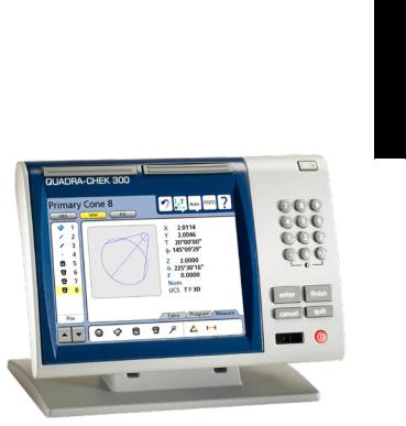
The Quadra-Chek 330 series is a family of advanced digital readout systems for performing 2, 3 and 4 axis measurements at very high levels of precision and accuracy. Dimensional inspection of components can be made using CMM touch probe systems as part of in-line production activities or final quality inspection.
Feature points are entered using fixed, indexing or friction touch probes. Feature type can automatically be determined by the system using Measure Magic technology. Level and skew compensation can be performed on mis-
aligned parts prior to measurements to eliminate the need for time-consuming fixturing.
The intuitive interface will be familiar to users of the QC-200 and other Metronics digital readouts. Operators will find the QC-330 easy to understand and use thanks to the large color touch screen LCD display.
The color LCD displays alphanumeric and graphic information for the current measurement, part features and measurement data clearly on one screen, eliminating the need to page or scroll or navigate for information.
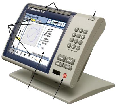
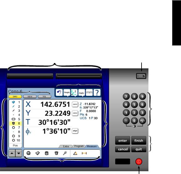
Touch screen controls select the feature to be measured, change operating and display modes, zero axes, and configure setup parameters. Touch screen controls change to support measurement-specific functions displayed on the LCD screen.
Front panel keys enter numeric data, turn the LCD on or off and send data to a printer or computer. Two wide keys located over the LCD can quickly be pressed without looking at the front panel to initiate frequently used functions programmed by the user. All front panel keys provide tactile sensory feedback, and key-press operations can be configured to generate an audible sound.
Overview 1
|
QC-300 Series User’s Guide |
|
Wide keys |
Print/Send data
Touch screen controls
 Numeric keypad
 Command keys
Color touch screen
LCD ON/OFF
Speaker and external speaker jack outputs are provided that can be adjusted for quiet or noisy environments. Ear phones can be plugged into the external speaker jack to facilitate silent operation in quiet environments.
Sequences of key-presses and touch probe contacts used to perform measurements can be recorded and stored as programs. These programs can be replayed later to perform complete measurement sequences. Sequences can be as simple as measuring a line, or can be expanded to include skew adjustment, datuming, the measurement of multiple features, tolerancing and printing reports of measurement results.
Measurement results can be saved to a USB flash drive, transmitted to a PC over the RS-232 port or printed on a USB printer.

Description of QC-330 Features
External footswitch
Touch probe |
|
Speaker jack |
input |
|
USB ports |
|
|
Encoder inputs
 RS-232 port
Tilt adjust
Overview 1
The compact ergonomic design and adjustable-tilt front panel of the QC-330 allow users to locate and mount the instrument in a wide variety of environments that accommodate nearly any viewing requirement. The tilt front panel can be adjusted and secured in any convenient position. Rubber feet on the bottom prevent slipping when the system is not permanently bolted to a work surface using the bolt holes provided in the bottom of the mounting stand.
Jacks are provided for an optional foot switch or hand switch. All the optional accessories for the QC-330 are shown in detail at the rear of this guide in Chapter 13: Options.
|
QC-300 Series User’s Guide |

Chapter 2:
Installation
The QC-330 is easy to install in a variety of basic and advanced measurement applications. This chapter describes how to unpack and install the QC-330. Repackaging instructions are also included for return shipments and for distributors and OEM customers that are configuring a QC-330 and shipping it to an end-user.
Unpacking the QC-330
Carefully remove the contents of the shipping carton.
NOTE
Save the carton and packaging materials in case future return shipment becomes necessary.
Installation 2
Inspect the components listed below for shipping damage. The contents of the carton includes:
• |
QC-330 instrument |
• |
Mounting stand and hardware |
• |
Power cord |
• |
Warranty registration card |
Shipments of other optional equipment in separate cartons might include:
• |
RS-232 serial cable |
• QC-Wedge software |
• |
Foot switch or hand switch |
|
If any components were damaged in shipment, save the packaging materials for inspection and contact your shipping agent for mediation. Contact your Metronics distributor for replacement parts.
|
QC-300 Series User’s Guide |
|
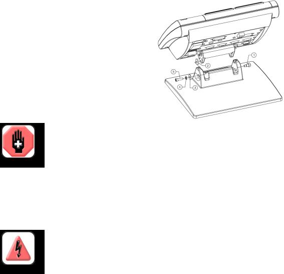
Assembling the mounting stand |
|
The QC-330 is secured to the swivel slots of the mounting stand by a shoulder |
|
screw, a cap screw and associated washers. |
|
Assemble the QC-330 to the mounting stand as shown. |
|
Tighten the shoulder screw (1), and then tighten the cap |
|
screw (5) and washers (3 & 4) so that the QC-330 will |
|
be secure when adjusted to the desired tilt position. |
|
Safety considerations |
|
The QC-330 is completely enclosed and no hazardous out- |
|
puts can come in contact with the user. Safety considerations |
|
are related to power connections and physical mounting. |
|
WARNING |
|
If the QC-330 falls from its mounting location, serious personal injury or damage to |
|
the equipment can result. |
|
Power cord and plug |
|
Do not locate the power cord where it can be walked on or will create a tripping hazard. Connect the 3-wire |
|
power plug to only a 3-wire grounded outlet. Never connect 2-wire to 3-wire adapters to the power cord |
|
or remove the third ground wire to fit the plug into a 2-wire electrical outlet. Modifying or overriding the |
|
third-wire ground creates a safety hazard and should not be permitted. |
|
DANGEROUS VOLTAGE |
|
Always disconnect the power cord from the source of AC power before unplugging |
|
it from the QC-330 power connector. The AC voltage available at electrical outlets is |
|
extremely dangerous and can cause serious injury or death. |
|
Electrical wiring and connections |
|
Perform regular inspections of all connections to the QC-330. Keep connections clean and tight. Locate |
|
cables away from moving objects. Do not create tripping hazards with power cords, input/output cables or |
|
other electrical wiring. |
|
Use shielded cables to connect to the serial RS-232 port. Make certain that cables are properly terminated |
|
and firmly connected on both ends. |
Safety and Power |
|
Location and mounting
Rest the QC-330 on a flat, stable surface, or bolt it to a stable surface from the bottom using four 10/32 screws fastened in the pattern shown at the right.
Installation 2
Power surge suppressor
Connect the QC-330 to power through a high-quality power surge suppressor. Surge suppressors limit the amplitude of potentially damaging power line transients caused by electrical machinery or lightning. When a surge suppressor is not used, power line transients can corrupt system memory or damage circuits.
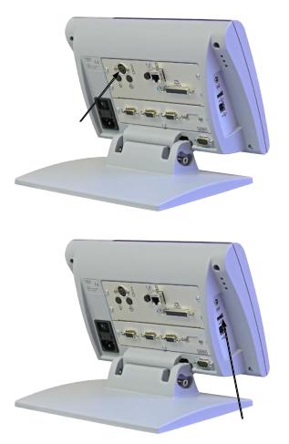
Connecting axis encoders
Axis encoders are attached to interface connectors on the rear of the QC-330. Many encoder interfaces are available to match the wide variety of encoders that can be used with the QC-330. The type of axis encoder connectors will vary depending on the application. Encoder inputs are specified as analog or TTL at the time of purchase and cannot be changed in
the field.
1 Verify that the QC-330 is off.
X, Y, Z and Q axis input connectors
2 Connect the axis encoders tightly to their connectors. An axis label is pro-
vided near each connector. Do not overtighten the connector screws.
Encoder input parameters must be configured later using the Encoder setup screen. Please refer to Chapter 10: Setup for details regarding encoder setup.
QC-300 Series User’s Guide
Connecting the touch probe input
The fixed or manually indexed touch probe is connected to the
Renishaw® connector on the rear of the QC-330.
1 Verify that the QC-330 is off.
2 Connect the touch probe to the Renishaw connector on the rear panel.
Touch probe connector
Connecting a printer
The QC-330 supports certain USB printers. Printer models should be specified by Metronics when the QC-330 is ordered, or approved by Metronics later.
1 Verify that the QC-330 and printer power are off. Connect the USB printer to the USB Type A port on the side of the enclosure.
2 Make sure the USB cable plug is fully inserted.
USB printer port

Connections
Connecting a computer
1Verify that the QC-330 and computer power are off.
2Connect a computer COM port to the QC-330 RS-232 serial port using a standard straight-through serial cable (Metronics part number 11B12176). Make sure the cable connectors are tight, but do not overtighten the connector screws.
3Apply power to the computer, and then the QC-330. The default QC-330 settings for communication over the RS-232 serial port are shown here.
• |
Baud rate: |
1200 |
• |
Parity: |
None |
• |
Data bits: |
7 |
• |
Stop bits: |
1 |
• |
Flow control: |
Hardware |
RS-232 serial port connector
4 Launch the computer application that will be used to communicate with the QC-330, and configure the communication properties of the COM port to match those of the QC-330.
Installation 2
Connecting an optional footswitch
The optional foot switch is connected to the RJ-45 connector on the rear of the QC-330.
1Verify that the QC-330 is off.
2Connect the foot switch to the RJ-45 connector on the rear connector panel.
Footswitch connector

10 |
QC-300 Series User’s Guide |
Warranty registration form
The warranty registration form included in the shipping carton should be completed and mailed as soon as possible. Also record the purchase and warranty information here so that it will be readily available later to support any necessary interactions with distributor or factory technical support personnel.
The software version can be found in the
Hardware setup screen. Refer to Chapter 10: Setup for screen descriptions.
Repackaging for shipment
Repackage the QC-330 in the original packaging as received from the factory, or equivalent. It is not necessary to ship the base when shipping the QC-330 for repair.
CAUTION
The original packaging must be duplicated and the LCD must be inserted face-up to prevent damage to the LCD screen.
Pay special attention to the following instructions:
1Connect any loose mounting hardware to the QC-330 instrument
2Repackage the foam and cardboard carton inserts as originally shipped from the factory.
3Place the QC-330 into shipping carton with the LCD facing up.
4Replace the warranty card and slip sheets found at the top of the carton. The “Before you begin” slip sheet should be inserted last.
What’s next?
Proceed to Chapter 10: Setup to configure your QC-330 for use. Follow the instructions for Minimum Setup requirements.
11
Chapter 3: User Interface
The QC-330 user interface consists of hardware front panel buttons and number keys that work in cooperation with software menus, buttons, and data fields shown on the color LCD touch screen. The hardware/ software interface is divided into the function areas listed and shown below.
• |
Screen functions |
• |
Command buttons and wide keys |
• |
Data display |
• |
Number keys |
• |
Measurement functions |
• |
LCD ON/OFF or delete features |
• |
Feature list |
• |
Printing reports and sending data |
• |
System functions |
|
|
Interface User 3
Wide keys |
Printing reports |
and sending data |
System functions
Screen functions
Number
keys
Feature |
Data |
|
display |
||
list |
||
|
Command
buttons
Measure functions
LCD ON/OFF and delete features
12 |
QC-300 Series User’s Guide |
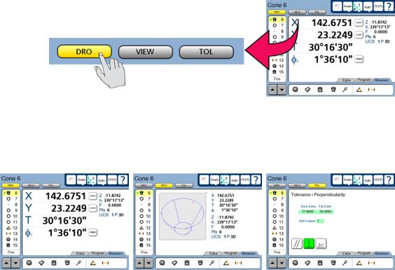
LCD Screen functions
The LCD functions are used to select screens that support operator activities.
Touch a button to select the desired screen.
• |
DRO |
Displays the digital readout |
• |
VIEW |
Displays the selected feature’s data cloud and physical geometry |
• |
TOL |
Displays the tolerance screens for entering and editing tolerances |
DRO screen |
VIEW screen |
TOL screen |
LCD Screen Functions
Data display
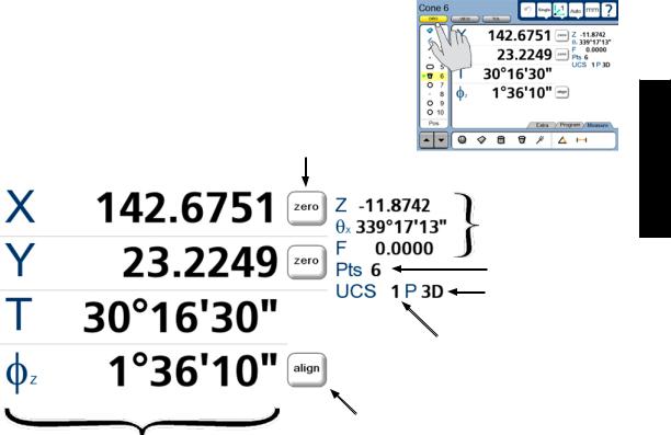
Data is displayed on the DRO, View and Tol screens.
DRO screen
Press the DRO button to display the DRO screen. Measurement data, reference frame, projection, part alignment controls and part datum controls are shown on the DRO screen.
Part datum controls
Feature data: minor coefficients
Data points
Projection
Reference frame ID
Part alignment control
Feature data: major coefficients
13
Interface User 3

14 |
QC-300 Series User’s Guide |
View screen
Press the VIEW button to display the VIEW screen. Measurement data, reference frame, projection and an image of the data cloud and resulting feature geometry are shown on the View screen.
Data cloud and feature geometry
Feature data: major coefficients
Feature data: minor coefficients
Data points
Projection
Reference frame ID
The view of the feature geometry is rotated by touching center or corner points at the edge of the image or by touching and dragging across the screen.
LCD Screen Functions |
15 |
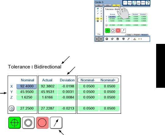
TOL screen
Press the TOL button to display the Tolerance screen. Tolerance data, tolerance type selections and tolerance specification fields are shown on the TOL screen.
Specification of nominal values
Tolerance
type
Measurement
results
Tolerance  specifications
Tolerance type selection controls
Interface User 3
16 |
QC-300 Series User’s Guide |
Measurement functions
The measurement functions are divided into three tabbed areas:
• |
Measure |
Select a measurement type, such as circle, line or sphere |
• |
Program |
Record, edit or play back a program of measurement steps |
• |
Extra |
Send data to the RS-232 port |
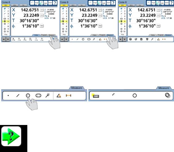
Selecting a measurement type
Measurement types are selected from the Measure tab. Touch the Measure tab repeatedly to display icons in the measure tab for the different 2D and 3D measurement types.
Touch the Measure tab to display |
then touch the Measure tab repeatedly to alternately display 2D and 3D |
measurement types... |
measurement types |
Touch a measure icon to select the desired measurement type. In some cases, such as when selecting circles and slots, related measurement types will also be presented as shown in this example of touching the circle icon to display the arc measure type.
Touching the circle measure icon... |
displays circle and arc measurement types |
NOTE
Details regarding performing measurements and the use of measurement tools are provided in Chapter 6: Measuring.
 Loading...