


 HEIDENHAIN
Working with the position display units
ND 520 ND 560 |
NDP 560 |
|
For two axes |
For three axes |
For panel mounting |
Actual value and input display
(7-segment LED, 8 decades with sign); top to bottom: X axis,
Y axis, ND 560 / NDP 560 only: Z axis
•Select coordinate axis
(Z axis only with ND 560 and NDP 560)
•Select axis-specific operating parameters
Numeric keypad and decimal point
|
|
|
|
X |
7 |
8 |
9 |
|
|
|
|
Y |
4 |
5 |
6 |
|
|
|
|
Z |
1 |
2 |
3 |
|
|
|
|
1 |
0 |
|
|
|
|
|
|
2 |
|
|
|
|
|
|
|
CL |
SPEC |
MOD |
ENT |
|
|
|
|
FCT |
|||
|
|
|
|
|
|||
REF |
1 |
2 |
in. |
SCL |
|
|
|
•Sign
•Change parameter
Confirm entry
•Call operating parameters
HEIDENHAIN
Status indicators
•Select datum
•Page backward in parameter list
• Page forward in parameter list
Datum setting
•Clear entry
•CL plus two-digit number: select parameter
•Clear parameter entry
Indicator
REF
1 / 2
in.
SCL
→
→

 ←
←
Meaning
Reference mark crossed over – datum points are now stored in nonvolatile memory.
Blinking: Waiting for confirmation from operator.
Datum point 1 / Datum point 2 currently active
Position values displayed in inches
Scaling factor active
Set workpiece edge as datum.
Blinking: Waiting for confirmation from operator.
Set centerline between two workpiece edges as datum. Blinking: Waiting for confirmation from operator.
The ND 520, ND 560 and NDP 560 are designed for use with HEIDENHAIN linear encoders with sinusoidal output signals.
The linear encoders have one reference mark or several (preferably distance-coded) reference marks. When a reference mark is crossed over, a signal is generated which identifies that position as a reference point.
After switch-on, crossing over the reference marks restores the relationship between axis slide positions and display values last established by datum setting. With encoders which have distance-coded reference marks, this requires a traverse of no more than 20 mm.
Switch-On
Turn on the power
Switch on the display unit with the power switch on the rear panel. The display shows 

 and REF blinks.
Switch on reference mark evaluation
Press ENT.
The display shows the value last assigned to the reference mark position.
REF glows and the decimal point blinks.
Cross over the reference mark in each axis
Move the axes one after the other until the display becomes active and the decimal point glows steadily.
The display unit is now ready for operation.
If you do not wish reference mark evaluation, press CL instead of ENT.
Datum Setting
The datum setting procedure assigns a specific axis position to the associated display value.
You can set two separate datum points and switch from one to the other with the touch of a key. Use datum 2 when you want to display incremental dimensions.
Select the datum.
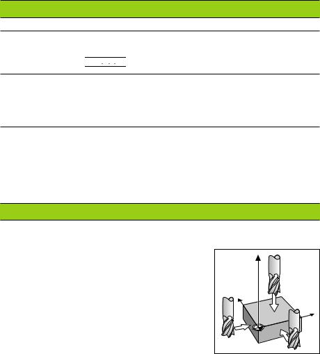
Select the coordinate axis in which the tool moves (for example, the X axis).
Touch the workpiece with the tool.
Enter the position of the tool center using the numeric keypad (for example, X = –5 [mm]). A minus sign cannot be entered until at least one digit is in the display.
Press ENT.
This stores the value for the tool position.
Follow same procedure for the other axes.
Z |
Y |
X |
Touching the workpiece

Datum Setting with an Edge Finder
The special functions of your display unit enable you to use a HEIDENHAIN KT edge finder to set a workpiece edge or the centerline between two workpiece edges as a datum. The position displays take into account the edge finder diameter which you entered in operating parameter P25.
If you are using the NDP 560 (which has no edge finder input) or if you want to use the special functions with a tool, please see the instructions on the next page.
Workpiece edge as datum |
|
|
Select the datum. |
|
|
Press the SPEC FCT key once. |
Z |
|
The indicator "Workpiece edge as datum" blinks. |
|
|
|
|
|
Press ENT. |
|
|
The indicator glows steadily. |
|
|
Select the coordinate axis in which the tool |
Y |
|
moves. The selected axis glows more brightly. |
|
X |
Probe the workpiece with the edge finder until |
X? |
|
the LEDs in the edge finder light up and the |
|
|
display shows the position of the workpiece edge. |
|
|
Enter the new coordinate value for the probed |
|
|
edge. |
Workpiece edge as datum |
|
|
|
Press ENT.
The workpiece edge is set to the new value, and the display shows the position of the edge finder relative to the new datum.
This function ends automatically.
Centerline between two workpiece edges as datum
Select the datum.
Press the SPEC FCT key twice. The indicator "Centerline as datum" blinks.
Press ENT.
The indicator glows steadily. |
Z |
|
Select the coordinate axis in which the tool |
||
moves. The selected axis glows more brightly. |
|
|
Probe the workpiece with the edge finder until |
|
|
the LEDs in the edge finder light up and the |
Y |
|
decimal point blinks. |
|
|
Probe the second workpiece edge with the edge |
X? |
|
finder until the LEDs in the edge finder light up |
||
X |
||
and the display shows the position of the |
|
|
centerline. The decimal point glows steadily. |
|
|
Enter the new coordinate value for the |
Centerline as datum |
|
centerline. |
||
|
Press ENT.
The centerline is now set to the new value and the display shows the position of the edge finder relative to the new datum.
This function ends automatically.
To cancel the datum setting function:
When the indicator for the function is blinking: press CL
When the indicator for the function is glowing steadily: press SPEC FCT
 Loading...