


 Loading...
Operating Instructions
ND 287
English (en) 11/2013

ND 287 screen
1
2
3
4
5
ND 287 front panel
7
6
Controls and displays
1 Status bar
Current operating mode: Actual Value, Distance-To-Go
Current display mode for input X1, X2 or coupled axes X1:X2
SCL shown in black: Scaling factor is active
COMP shown in black: Error compensation or axis-error compensation is active for the currently displayed axis or coupled axes.
Elapsed time of running stopwatch: If the stopwatch is stopped, the box appears dimmed.
mm, inch, DEG, DMS or rad: Currently active unit of measure
Currently active datum: The ND 287 allows you to work with two different datums.
Indicates the soft-key page (soft-key row) you are currently on.
2Position display: Current position value (length or angle), or other measured value
3Message line for displaying information, errors or warnings
4Status display:
<• / = / >: The first three symbols become effective when tolerance checking and sorting mode is activated.
MIN, ACTL or MAX and DIFF: Minimum, current or m aximum measured value of a series of measurements, or difference between minimum and maximum measured value.
SET: If you enter a new value during datum setting, the SET symbol will start flashing.
REF: The REF symbol is flashing until the reference mark evaluation for the displayed axis has been completed (if an incremental encoder is connected).
P0-P9: Selected part is displayed for the sorting and tolerance checking mode.
5 and 6 Soft keys and soft-key buttons for executing functions
1,2,3,4... Numeric input keys
ENTER |
Use the ENTER key to confirm your entry or to return to the previous screen. |
CUse the C key to clear an entry, acknowledge an error message or return to the previous screen.
The NAVIGATION key moves through the soft-key pages (soft-key rows).
7Use the UP or DOWN arrow key to move between fields within a form or menu items (parameters) within a menu.

ND 287 rear panel
1
3
2
X41 |
X32/X31 |
X26(X27) |
X2 |
X1 |
Connections
1Power switch
2Power connection with fuse
3Ground (protective earthing)
X1 |
Encoder module for connecting a HEIDENHAIN encoder with 11 µApp, 1 Vpp or EnDat interface (purely |
|
serial) |
Option: Analog module for connecting an analog sensor
X2 Optional:
Encoder module for connecting a HEIDENHAIN encoder with 11 µApp, 1 Vpp or EnDat 2.1/2.2 interface for a second axis or
Analog module for connecting an analog sensor, primarily a temperature sensor for axis-error compensation
X26 (X27) |
Option: Ethernet module (100baseT) for network connection via TCP/IP protocol |
|
|
X32/X31 |
Two serial ports for data transfer: RS-232-C/V.24 (X31) and USB Type B (UART, X32) |
|
|
X41 |
Switching inputs and outputs at D-sub connection |
|
|

Introduction
Software version
The software version is shown on the power-up screen of the ND 287.
This manual describes the functions that are available in the ND 287 and the installation of the units.
Symbols within notes
Every note is marked with a symbol on the left indicating to the operator the type and/or potential severity of the note.
General information
e. g. on the behavior of the ND 287.
Refer to accompanying documents
e.g. when a special tool is required for a function.
Danger to the operator, workpiece or internal components
e.g. danger of collision
Electrical hazard
e. g. danger of electrical shock when opening a housing.
The ND 287 must be prepared by a qualified and authorized technician to perform this function.
Fonts
The chart below shows how the different variables (soft keys, hard keys, forms and form fields) are represented within the text of this manual:
Soft keys – SETUP soft key
Hard keys – ENTER hard key
Menus and forms – UNITS OF MEASURE form
Parameters and input fields – ANGULAR field
Data in fields - ON, OFF
Introduction
ND 287 |
5 |

I Working with the ND 287 position display unit |
..... |
13 |
|
|
||||||||
I – 1 ND 287 position display unit ..... |
14 |
|
|
|
|
|
|
|
||||
I – 2 Fundamentals of positioning ..... |
16 |
|
|
|
|
|
|
|
||||
Datums ..... |
16 |
|
|
|
|
|
|
|
|
|
|
|
Actual position, nominal position and distance-to-go ..... |
17 |
|
|
|||||||||
Absolute workpiece positions |
..... |
18 |
|
|
|
|
|
|
||||
Incremental workpiece positions ..... |
18 |
|
|
|
|
|
|
|||||
Incremental position encoders ..... |
19 |
|
|
|
|
|
|
|||||
Absolute position encoders ..... |
19 |
|
|
|
|
|
|
|||||
Reference marks |
|
..... 20 |
|
|
|
|
|
|
|
|
||
I – 3 Basic functions of the ND 287 ..... |
21 |
|
|
|
|
|
|
|||||
ND 287 power-up |
|
..... 21 |
|
|
|
|
|
|
|
|
||
Reference mark evaluation ..... |
22 |
|
|
|
|
|
|
|
||||
Working without reference mark evaluation ..... |
22 |
|
|
|
||||||||
ND 287 shutdown |
..... 22 |
|
|
|
|
|
|
|
|
|||
Standard screen layout ..... |
23 |
|
|
|
|
|
|
|
|
|||
Soft-key functions on the standard screen ..... |
25 |
|
|
|
|
|||||||
Axis display mode ..... |
27 |
|
|
|
|
|
|
|
|
|||
Data input ..... |
27 |
|
|
|
|
|
|
|
|
|
|
|
Integrated help system ..... |
28 |
|
|
|
|
|
|
|
|
|||
Data input forms ..... |
|
29 |
|
|
|
|
|
|
|
|
|
|
Instruction box messages ..... |
|
29 |
|
|
|
|
|
|
||||
Error messages ..... |
|
29 |
|
|
|
|
|
|
|
|
|
|
I – 4 Job Setup ..... |
30 |
|
|
|
|
|
|
|
|
|
|
|
Operating modes |
..... |
30 |
|
|
|
|
|
|
|
|
|
|
Datum setting ..... |
|
31 |
|
|
|
|
|
|
|
|
|
|
Setting the display value for one axis or for two axes in the X1 or X2 display mode ..... |
31 |
|
||||||||||
Setting the display value for two axes in display mode X1:X2 (applies to X1+X2, X1-X2, f(X1,X2)) ..... |
32 |
|||||||||||
Calling the JOB SETUP menu ..... |
|
33 |
|
|
|
|
|
|
||||
Unit of measure ..... |
|
34 |
|
|
|
|
|
|
|
|
|
|
Scaling factor ..... |
35 |
|
|
|
|
|
|
|
|
|
||
Value for datum point ..... |
36 |
|
|
|
|
|
|
|
|
|||
Stopwatch ..... |
36 |
|
|
|
|
|
|
|
|
|
|
|
Console adjustment ..... |
37 |
|
|
|
|
|
|
|
|
|||
Language ..... |
37 |
|
|
|
|
|
|
|
|
|
|
|
Switching signals |
..... |
38 |
|
|
|
|
|
|
|
|
|
|
Measured-value output ..... |
39 |
|
|
|
|
|
|
|
|
|||
Function of external inputs ..... |
40 |
|
|
|
|
|
|
|
||||
Compensation using a reference part ..... |
41 |
|
|
|
|
|
||||||
ND 287 |
7 |
|
|
|
|
|
|
|

I – 5 Series of measurements and statistical process control ..... |
42 |
|
||||||
Functions ..... |
42 |
|
|
|
|
|
|
|
Switching between series of measurements and SPC mode ..... |
42 |
|||||||
Calling the SERIES OF MEASUREMENTS menu ..... |
43 |
|
|
|||||
Analysis of series of measurements ..... |
43 |
|
|
|
||||
Setting up a series of measurements ..... |
44 |
|
|
|
||||
Defining the display for a series of measurements ..... |
46 |
|
||||||
Setting the position or speed display ..... |
47 |
|
|
|
||||
Defining the record mode |
..... |
47 |
|
|
|
|
||
Starting and stopping a series of measurements ..... |
48 |
|
|
|||||
Calling the SPC menu ..... |
49 |
|
|
|
|
|
||
SPC analysis ..... |
|
49 |
|
|
|
|
|
|
Setting up SPC ..... |
52 |
|
|
|
|
|
|
|
Samples ..... |
52 |
|
|
|
|
|
|
|
Tolerances ..... |
53 |
|
|
|
|
|
|
|
Control limits |
..... 54 |
|
|
|
|
|
|
|
Statistical distribution ..... |
55 |
|
|
|
|
|||
Measured value recording |
..... 55 |
|
|
|
|
|||
Deleting SPC statistics ..... |
55 |
|
|
|
|
|
||
Starting and stopping SPC |
..... |
56 |
|
|
|
|
||
I – 6 Sorting and tolerance checking ..... |
58 |
|
|
|
|
|||
Sorting function ..... |
58 |
|
|
|
|
|
|
|
Defining the sorting parameters and part tolerances ..... |
|
59 |
|
|||||
I – 7 Error messages |
..... |
60 |
|
|
|
|
|
|
Overview ..... |
60 |
|
|
|
|
|
|
|
8

.....II Installation, specifications |
|
63 |
|
|
|
|
|
|
|
|
||
II – 1 Installation and electrical connection ..... |
64 |
|
|
|
|
|
|
|||||
Items supplied ..... |
64 |
|
|
|
|
|
|
|
|
|
|
|
Optional accessories |
..... |
64 |
|
|
|
|
|
|
|
|
||
Mounting ..... |
65 |
|
|
|
|
|
|
|
|
|
|
|
Environmental conditions ..... |
65 |
|
|
|
|
|
|
|
||||
Mounting location ..... |
65 |
|
|
|
|
|
|
|
|
|||
ND 287 – Mounting and installation ..... |
65 |
|
|
|
|
|
||||||
Electromagnetic compatibility/ |
|
|
|
|
|
|
|
|
||||
CE compliance ..... |
66 |
|
|
|
|
|
|
|
|
|
|
|
Electrical connection ..... |
67 |
|
|
|
|
|
|
|
|
|||
Electrical requirements ..... |
67 |
|
|
|
|
|
|
|
||||
Wiring the power connector ..... |
|
67 |
|
|
|
|
|
|
||||
Grounding |
..... 67 |
|
|
|
|
|
|
|
|
|
|
|
Preventative maintenance or repair ..... |
68 |
|
|
|
|
|
|
|||||
Connecting the encoders ..... |
68 |
|
|
|
|
|
|
|
|
|||
D-sub connection X1/X2 (15-pin, female) for the following input signals |
..... 68 |
|
|
|||||||||
Optional: Analog module with ±10 V interface at input X1 or X2 for connecting an analog sensor ..... |
69 |
|
||||||||||
II – 2 Installation Setup ..... |
70 |
|
|
|
|
|
|
|
|
|
|
|
INSTALLATION SETUP menu ..... |
70 |
|
|
|
|
|
|
|||||
Setting up the encoder ..... |
|
71 |
|
|
|
|
|
|
|
|
||
Incremental linear encoder ..... |
72 |
|
|
|
|
|
|
|||||
Incremental rotary encoder ..... |
73 |
|
|
|
|
|
|
|||||
Absolute encoder ..... |
74 |
|
|
|
|
|
|
|
|
|||
Using an absolute multiturn rotary encoder as a linear encoder ..... |
74 |
|
|
|
||||||||
Analog sensor with ±10 V interface, preferably a temperature sensor ..... |
75 |
|
|
|||||||||
Configuring the display ..... |
|
76 |
|
|
|
|
|
|
|
|
||
Linear encoder ..... |
76 |
|
|
|
|
|
|
|
|
|
||
Rotary encoder |
..... 76 |
|
|
|
|
|
|
|
|
|
||
Analog sensor for compensation |
..... 76 |
|
|
|
|
|
|
|||||
Counter settings ..... |
77 |
|
|
|
|
|
|
|
|
|
|
|
Setting the display modes of the axes ..... |
78 |
|
|
|
|
|
||||||
Formula for coupled position ..... |
|
78 |
|
|
|
|
|
|
||||
Error compensation ..... |
79 |
|
|
|
|
|
|
|
|
|
||
Linear error compensation (not for rotary encoders) ..... |
80 |
|
|
|
|
|||||||
Non-linear error compensation ..... |
81 |
|
|
|
|
|
|
|||||
Setting up the serial port ..... |
85 |
|
|
|
|
|
|
|
|
|||
Setting up the data interface ..... |
|
85 |
|
|
|
|
|
|
||||
Diagnostics ..... |
87 |
|
|
|
|
|
|
|
|
|
|
|
Keypad test ..... |
87 |
|
|
|
|
|
|
|
|
|
|
|
Display test ..... |
87 |
|
|
|
|
|
|
|
|
|
|
|
Encoder test ..... |
88 |
|
|
|
|
|
|
|
|
|
|
|
Power supply ..... |
90 |
|
|
|
|
|
|
|
|
|
|
|
Switching inputs test ..... |
91 |
|
|
|
|
|
|
|
|
|||
Switching outputs test ..... |
92 |
|
|
|
|
|
|
|
|
|||
ND 287 |
|
|
|
|
|
|
|
|
|
|
9 |
|
|
|
|
|
|
|
|
|
|
|
|
|
|
|
|
|
|
|
|
|
|
|
|
|
|
|

II – 3 Switching inputs and outputs ..... |
93 |
|
|
|
|
|
|||
Switching inputs at D-sub connection X41 |
..... |
93 |
|
|
|||||
Input signals |
..... |
94 |
|
|
|
|
|
|
|
Signal level of inputs ..... |
94 |
|
|
|
|
|
|||
Ignoring the reference mark signals ..... |
94 |
|
|
|
|||||
Switching outputs at D-sub connection X41 ..... |
95 |
|
|
||||||
Output signals ..... |
95 |
|
|
|
|
|
|
|
|
Signal level of outputs ..... |
95 |
|
|
|
|
|
|||
Trigger limits |
..... |
96 |
|
|
|
|
|
|
|
Sorting limits |
..... |
97 |
|
|
|
|
|
|
|
Trigger signal for error ..... |
97 |
|
|
|
|
|
|||
Zero crossover ..... |
97 |
|
|
|
|
|
|
||
II – 4 Encoder parameters ..... |
98 |
|
|
|
|
|
|
||
Table values ..... |
98 |
|
|
|
|
|
|
|
|
HEIDENHAIN linear encoders |
..... 98 |
|
|
|
|
|
|||
HEIDENHAIN rotary encoders |
..... 99 |
|
|
|
|
|
|||
II – 5 Data interface ..... |
100 |
|
|
|
|
|
|
|
|
Data communication ..... |
100 |
|
|
|
|
|
|
||
Serial data transfer with the Import or Export function ..... |
101 |
||||||||
Data transfer from the ND 287 to a printer |
..... 101 |
|
|||||||
Data transfer from the ND 287 to a PC ..... |
|
101 |
|
|
|||||
Importing data into the ND 287 from a PC ..... |
102 |
|
|||||||
Data format ..... |
|
102 |
|
|
|
|
|
|
|
Control characters ..... |
102 |
|
|
|
|
|
|
||
Software update (firmware update) installation ..... |
103 |
|
|||||||
Wiring the connecting cable ..... |
104 |
|
|
|
|
|
|||
USB Type B (UART), socket as per IEC 61076-3-108 ..... |
105 |
||||||||
External operation via RS-232-C/V.24 or USB interface ..... |
106 |
||||||||
Key commands ..... |
106 |
|
|
|
|
|
|
||
Description of key commands ..... |
107 |
|
|
|
|
||||
Key is pressed (TXXXX commands) ..... |
108 |
|
|
||||||
Output of screen contents (AXXXX commands) |
..... 108 |
||||||||
Execute function (FXXXX commands) ..... |
112 |
|
|
||||||
Execute special function (SXXXX commands) ..... |
112 |
|
|||||||
10
II – 6 Measured value output ..... |
113 |
|
|
|
|
|
|
|
||
Alternatives for starting measured value output ..... |
113 |
|
|
|||||||
Measured value output after a trigger signal ..... |
113 |
|
|
|
||||||
Propagation times ..... |
113 |
|
|
|
|
|
|
|
||
Duration of measured value transfer ..... |
113 |
|
|
|
|
|||||
Measured-value output via the serial data interface X31 or X32 |
..... 114 |
|
||||||||
Propagation times ..... |
114 |
|
|
|
|
|
|
|
||
Duration of measured value transfer ..... |
115 |
|
|
|
|
|||||
Example: Data sequence during measured-value output ..... |
115 |
|
||||||||
II – 7 Input and output of parameter list and error compensation table |
..... 116 |
|
||||||||
Text file ..... |
116 |
|
|
|
|
|
|
|
|
|
Output format of the parameter list ..... |
117 |
|
|
|
|
|
||||
First line ..... |
117 |
|
|
|
|
|
|
|
|
|
Second line ..... |
117 |
|
|
|
|
|
|
|
|
|
Subsequent lines for the individual parameters ..... |
117 |
|
|
|||||||
Last line |
..... |
117 |
|
|
|
|
|
|
|
|
Examples of parameter lists ..... |
118 |
|
|
|
|
|
|
|||
ND 287 with rotary encoder connected to input X1 |
..... 118 |
|
|
|||||||
ND 287 with two rotary encoders connected to inputs X1 and X2 (optional) ..... |
123 |
|||||||||
Output format of the error compensation table ..... |
128 |
|
|
|||||||
First line ..... |
128 |
|
|
|
|
|
|
|
|
|
Second line ..... |
128 |
|
|
|
|
|
|
|
|
|
Third line ..... |
128 |
|
|
|
|
|
|
|
|
|
Fourth line (only if second axis input is available, optional) ..... |
129 |
|
||||||||
Fifth line ..... |
129 |
|
|
|
|
|
|
|
|
|
Sixth line ..... |
129 |
|
|
|
|
|
|
|
|
|
Seventh line |
..... 130 |
|
|
|
|
|
|
|
|
|
Subsequent lines for further compensation values ..... |
130 |
|
|
|||||||
Last line |
..... |
130 |
|
|
|
|
|
|
|
|
Examples of error compensation tables |
..... |
131 |
|
|
|
|
||||
ND 287 with linear encoder connected to input X1 ..... |
131 |
|
|
|||||||
ND 287 with two linear encoders connected to inputs X1 and X2 (optional) ..... |
133 |
|||||||||
ND 287 with rotary encoder connected to input X1 |
..... 135 |
|
|
|||||||
II – 8 Specifications for |
..... 137 |
|
|
|
|
|
|
|
|
|
ND 287 ..... |
137 |
|
|
|
|
|
|
|
|
|
II – 9 Dimensions ..... |
140 |
|
|
|
|
|
|
|
|
|
ND 287 ..... |
140 |
|
|
|
|
|
|
|
|
|
II – 10 Accessories |
..... |
141 |
|
|
|
|
|
|
|
|
ID numbers for accessories ..... |
141 |
|
|
|
|
|
|
|||
Mounting the input assemblies |
..... 142 |
|
|
|
|
|
|
|||
Mounting base for installation in 19-inch electrical cabinet ..... |
143 |
|
||||||||
ND 287 |
11 |
|
|
|
|
|
|
|

12

Working with
the ND 287 position display unit
ND 287 |
13 |

I – 1 ND 287 position display unit
I – 1 ND 287 position display unit
The ND 287 position display unit from HEIDENHAIN is designed for measuring devices, adjustment and testing equipment, automated tasks, as well asinfeed and positioning tasks with up to two axes that can be moved manually.
Linear/angular/rotary encoders, length gauges or analog sensors can be connected to the ND 287. The ND 287 features two slots for the connection of modular input assemblies:
An encoder module for connecting an incremental photoelectrical
HEIDENHAIN encoder with sinusoidal 11 µApp, 1 Vpp signals or an |
|
|
absolute HEIDENHAIN encoder with bidirectional EnDat interface |
|
|
(purely serial) is a standard item supplied with the position display |
|
|
unit. |
Fig. I.1 ND 287 |
|
Optional modules that can be easily adapted to the ND's |
||
|
||
requirements: |
|
|
Second encoder module for connecting aHEIDENHAIN encoder |
|
|
with 11 µApp, 1 Vpp or EnDat interface (purely serial) or |
|
|
Analog module for connecting an analog sensor with ±10 V |
|
|
interface, primarily a temperature sensor for axis-error |
|
|
compensation |
|
|
Sorting and tolerance checking function with capacity for saving |
|
|
the tolerances of 10 parts |
|
|
The following functions are available on the ND 287: |
|
Multilingual user guidance: Language can be selected by the user
REF reference-mark evaluation for distance-coded or single reference marks
Display of position value (length or angle), traversing speed for series of measurements or other measured values from analog sensors
Distance-To-Go or Actual Value operating mode
Two datums
Scaling factor
Stopwatch
Reset or Preset function, also through external signal
Linear or non-linear error compensation for axis-error compensation
Switching inputs and outputs
14 |
I Working with the ND 287 position display unit |

Series of measurements:
Sorting measured values and finding the Minimum, Maximum, Sum, Difference or a definable coupled position value.
Displaying the sorting results in order to intervene, if necessary.
Memory capacity for series of measurements: Up to 10 000 measured values per axis.
Analysis of series of measurements: Arithmetical mean value, standard deviation, graphical representation of all measured values with minimum, maximum and mean value of the series of measurements.
Measured-value acquisition by external signal or selectable sampling interval, or by pressing the ENTER key.
Statistical Process Control (SPC):
Calculation of arithmetical mean value, standard deviation and range. Displaying graphs or histograms with symmetrical or asymmetrical density function.
Process capability indices cp and cpk, quality control charts for mean value, standard deviation and range.
Measured-value acquisition by external signal or by pressing the ENTER key.
FIFO memory capacity: Up to 1000 measured values.
There are two serial ports for transmitting measured values,
compensation values or configuration parameters to a PC or printer: The data can be transferred via the RS 232-C/V.24 or the USB Type B (UART) interface. It is also possibl e to download software via the serial interface.
Diagnostic functions for testing the encoder, the keyboard, the screen, the supply voltage and the switching inputs/outputs.
On the ND 287, one measured value can be displayed in large characters on the screen at any one time. If two encoders are connected to the ND, you can switch the display from the position value supplied by the first encoder to the position value supplied by the second encoder, or to a defined coupled position value.
The integrated help system provides information and assistancein any situation.
I – 1 ND 287 position display unit
ND 287 |
15 |
I – 2 Fundamentals of positioning
I – 2 Fundamentals of positioning
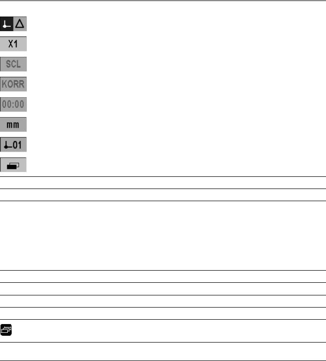
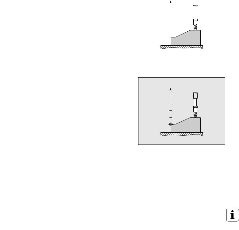
Datums
The workpiece drawing identifies a certain point on the workpiece |
|
|
|
|
|
|
|
|
|
|
|
(usually a corner) as the absolute datum and perhaps one or more |
|
|
|
|
|
other points as relative datums. |
|
Z |
|||
The datum setting procedure establishes these points as the origin of |
? |
|
|
|
|
|
|
|
|
||
the absolute or relative coordinate systems. The workpiece, which is |
|
|
|
|
|
aligned with the machine axes, is moved to a certain position relative |
? |
|
|
|
|
|
|
|
|
||
to the length gauge and the display is set either to zero or to another |
|
|
|
|
|
appropriate value. |
? |
|
|
|
|
|
|
|
|
||
|
|
|
|
|
|
|
? |
|
|
|
|
|
|
|
|
|
|
|
|
|
|
|
|
|
? |
|
|
|
|
|
|
|
|
|
|
|
|
|
|
|
|
Fig. I.2 Length gauge without datum setting: Unknown assignment of measured values to positions
Z
40
30
20
10
0
Fig. I.3 Length gauge with datum setting: Known assignment of measured values to positions
16 |
I Working with the ND 287 position display unit |
Actual position, nominal position and distance-to-go
The position of the length gauge at any given moment is called the actual position, while the position that the length gauge is to move to is called the nominal position. The distance from the nominal position to the actual position is called the distance-to-go (see Fig. I.4).
I R
S
Fig. I.4 Nominal position S, actual position I and distance-to-go R
I – 2 Fundamentals of positioning
ND 287 |
17 |
I – 2 Fundamentals of positioning
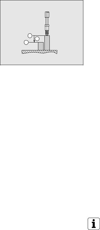
Absolute workpiece positions
Each position on the workpiece is uniquely identified by its absolute coordinates (see Fig. I.5).
Example: Absolute coordinates of position 1: Z = 20 mm
If you are drilling or milling a workpiece according to a workpiece drawing with absolute coordinates, you are moving the tool or length gauge to the value of the coordinates.
20 
 1
1
0 
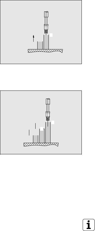
Incremental workpiece positions
A position can also be referenced to the preceding nominal position. For this, the relative datum must be set to the preceding nominal position. Such coordinates are referred to as incremental coordinates (increment = increase). They are also called incremental or chain dimensions (since the positions are defined as a chain of dimensions). Incremental coordinates are identified by a preceding I.
Example: Incremental coordinate of position 3 referenced to position 2 see Fig. I.6.
Absolute coordinate of position 2: Z = 10 mm Incremental coordinates of position 3: IZ = 10 mm
If you are drilling or milling a workpiece according to a workpiece drawing with incremental coordinates, you are moving the tool or length gauge by the value of the coordinates.
Fig. I.5 Position 1: definition through absolute coordinates
10 
 3 10
3 10  2
2
0 
Fig. I.6 Position 3: definition through incremental coordinates
18 |
I Working with the ND 287 position display unit |
Incremental position encoders
Incremental linear and rotary encoders from HEIDENHAIN convert the movements of, for example, a length gauge into electrical signals. A position display unit, such as the ND 287, constantly evaluates these signals and calculates the actual positions of the length gauge, which it displays as a numerical value on the screen.
If there is a power interruption, the calculated position will no longer correspond to the actual position of the length gauge. When power is restored, you can re-establish this relationship with the aid of the reference marks on the position encoders and the ND 287's reference mark evaluation feature.
Absolute position encoders
Absolute linear and angle encoders from HEIDENHAIN transmit the absolute position value to the position display unit immediately after switch-on. This way the assignment of the actual position to the position of, for example, a length ga uge is re-established directly after switch-on.
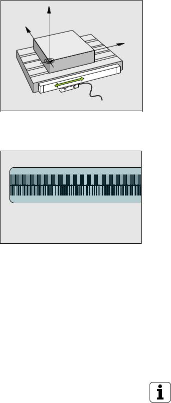
The encoder reads the absolute position information directly from the scale graduation (see Fig. I.8), and transmits it serially to the position display unit via the bidirectional EnDat interface.
Z |
Y |
X |
Fig. I.7 Linear position encoder, here for the X axis
I – 2 Fundamentals of positioning
Fig. I.8 Scale grating for absolute position encoders
ND 287 |
19 |

I – 2 Fundamentals of positioning
Reference marks
Encoders normally contain one or more reference marks (see Fig. I.9) which the ND 287's reference mark evaluation feature uses to reestablish datum positions after a power interruption. There are two main options available for reference marks: fixed and distance-coded.
Encoders with distance-coded reference marks have marks separated by a specific encryption pattern that allows the ND 287 to use any two pair of marks along the length of the encoder to reestablish the prior datums. This conf iguration means that the operator only has to travel a very short distance, anywhere along the encoder, to re-establish the datums when the ND 287 is turned back on.
Encoders with fixed reference marks have one or more marks on fixed intervals. To re-establish the datums correctly, it is necessary to use the same exact reference mark, during the reference mark evaluation routine, that was used when the datum was first established.
|
Danger to workpiece! |
Fig. I.9 Linear scales – with distance-coded |
|
The established datums cannot be restored from one |
reference marks (upper illustration) and one |
|
reference mark (lower illustration) |
|
|
power cycle to the next if the reference marks were not |
|
|
|
|
|
crossed before the datums were set. |
|
|
|
|
20 |
I Working with the ND 287 position display unit |
I – 3 Basic functions of the ND 287
ND 287 power-up
Switch on the ND 287. The power switch is located onthebackoftheND.AfterswitchingtheND 287on, or after a power failure, the power-up screen will appear (see Fig. I.10). The green LED on the front panel lights up. The power-up screen shows the position display unit model as well as the ID and version number of the currently installed software.
Press the LANGUAGE soft key if you want to change the conversational language (see Fig. I.11). Press ENTER to confirm your selection.
Press the HELP soft key to call the integrated help system.
Press any key to call the standard screen.
Your ND 287 is now ready for operation in the Actual Value operating mode. If an incremental encoder is connected to the ND, the REF symbol is flashing. At this point the reference mark evaluation should be completed (see "Reference mark evaluation" on page 22).
If an absolute encoder is connected to the ND, the encoder automatically transmits the absolute position value to the position display unit.
If necessary, you can change the language later, see "Language" on page 37.
To update your software version (firmware version), see "Softwareupdate(firmwareup date)installation"onpage 103.
The idle time after which the ND activates the screen saver can be defined (factory default setting: 120 min, see "Console adjustment" on page 37). The red LED on the front panel lights up. To reactivate the screen, press any key or move the encoder.
You can deactivate the power-up screen in order to display the standard screen immediately after power up (see "Counter settings" on page 77).
Fig. I.10 Power-up screen
Fig. I.11 Selecting the language
I – 3 Basic functions of the ND 287
ND 287 |
21 |
I – 3 Basic functions of the ND 287
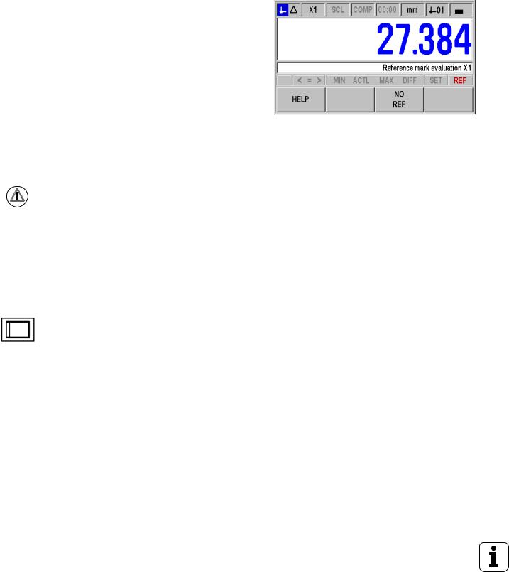
Reference mark evaluation
The ND 287's REF reference mark evaluation feature automatically reestablishes the relationship between axis-slide or length gauge positions and display values that you last defined by setting the datum.
Reference mark evaluation if an incremental encoder is connected (see Fig. I.12):
If the REF symbol is flashing, cross over the reference marks.The REF mark evaluation feature determines the correct display
value and the REF symbol stops flashing. |
|
Working without reference mark evaluation |
|
Press the NO REF soft key to exit the reference mark evaluation |
Fig. I.12 Screen for establishing reference marks |
routine and continue. |
|
In order to activate the reference mark evaluation feature at a later |
|
time, you can apply an external signal to pin 25 at connection X41 |
|
(see "Setting up the encoder" on page 71), or you can switch the |
|
ND 287 off and then back on. |
|
|
|
Danger to workpiece! |
|
If an encoder is set up without reference marks, or if the |
|
reference marks have not been crossed over, then the |
|
REF indicator will appear dimmed, and datums set from |
|
any axis will be lost once power is turned off. This means |
|
that it is not possible to re-establish the relationship |
|
between axis slide positions and display values after a |
|
power interruption (switch-off). |
|
|
|
ND 287 shutdown |
|
|
|
Switch off the ND 287. The measured values of a |
|
series of measurements will not be retained on a |
|
power cycle. The parameter settings, the error |
|
compensation tables or measured values that have |
|
been saved during statistical pr ocess control will stay |
|
in memory. |
|
|
|
|
|
22 |
I Working with the ND 287 position display unit |

Standard screen layout
In addition to displaying position information, the ND 287 standard screen also displays information on settings and operating modes at any time (see Fig. I.13). The standard screen is divided into the following areas:
1 Status bar
Current operating mode: Actual Value, Distance-To-Go.
X1, X2 or X1:X2: Current display mode of axis or coupled axes.
SCL shown in black: Scale factor is active.
COMP shown in black: The error compensation or axis-error compensation is active for the currently displayed axis or coupled axes.
Elapsed time of running stopwatch: If the stopwatch is stopped, the box appears dimmed.
MM, INCH, DEG, DMS or RAD: Currently active unit of measure.
Currently active datum: The ND 287 allows you to work with two different datums.
Indicates the soft-key page (soft-key row) you are currently on.
2Position display
Length display:
Current axis value with algebraic sign.
Angle display:
Current angle value with algebraic sign and unit of measure for display values in degrees, minutes or seconds.
When displaying the traversing speed in the series of measurements mode, the ND 287 shows the unit of speed in lowercase at the left edge of the screen.
3Message line
The message line provides information on the required data input or procedures, which is intended to support you in using the position display unit.
If errors or warnings occur, they show up in red letters in the message line. Acknowledge the message with the C key.
At the left edge of the message line the ND 287 displays a measured-value counter in the series of measurements mode, and a sample counter in the SPC mode.
If you have activated axis-error compensation with a temperature sensor, the ND shows the value measured by the temperature sensor at the left edge of the message line.
If a multiturn rotary encoder is connected, the ND shows the number of revolutions at the right edge of the message line.
1
2
3
4
5
Fig. I.13 Standard screen
I – 3 Basic functions of the ND 287
ND 287 |
23 |

I – 3 Basic functions of the ND 287
4Status display
P0-P9: The symbol for the selected part becomes active once you have activated the sorting and tolerance checking mode.
< / = / >: The first three symbols become active once you have activated the tolerance checking and sorting mode, as well as during Statistical Process Control (SPC). The symbols are shown in red if the current value is less than the lower sorting limit or greater than the upper sorting limit. Green indicates that the value is within the two sorting limits.
MIN, ACTL or MAX and DIFF: The symbols are only active, while a series of measurements is running. They indicate the display mode you have selected.
Set: If you enter a new value during datum setting, the SET symbol will start flashing.
REF: The REF symbol is flashing in red until the reference mark evaluation for the displayed axis has been completed (if an incremental encoder is connected).
5Soft keys
The NAVIGATION key (shown at left) allows you to move through the three pages of selectable soft-key functions. Press the corresponding soft key directly below each soft key label to execute the soft-key function. The soft-key assignment varies depending on the ND's operating mode.
24 |
I Working with the ND 287 position display unit |

Soft-key functions on the standard screen
There are three pages (rows) of soft-key functions. Use the NAVIGATION key (shown at left) to move through the pages.
The page indicator in the status bar shows the number of
pages. The darkened page indicates the page you are currently Fig. I.14 Page indicator on. This manual provides more information about each soft key
on the pages indicated in the table below. Soft key page 1:
Soft key |
Function |
Page |
SETUP |
Opens the JOB SETUP menu and |
Page 30 |
|
provides access to the |
|
|
INSTALLATION SETUP soft key. |
|
|
|
|
MEAS. |
Opens the SERIES OF |
Page 42 |
SERIES |
MEASUREMENTS menu. |
|
|
|
|
START MEAS. |
Starts a series of measurements. |
Page 48 |
SERIES |
|
|
|
|
|
SPC |
Opens the SPC menu. |
Page 49 |
|
|
|
START |
Starts the SPC function. |
Page 56 |
SPC |
|
|
|
|
|
PART |
Opens the SELECT PART menu. |
Page 58 |
TOLERANCE |
|
|
|
|
|
Soft key page 2: |
|
|
|
|
|
Soft key |
Function |
Page |
HELP |
Calls the integrated help system. |
Page 28 |
|
|
|
Transmits the current measured |
Page 113 |
|
|
value to a connected PC or printer |
|
|
via the serial interface. |
|
|
|
|
Distance-to-go |
Switches the display between |
Page 30 |
on |
operating modes Actual Value/ |
|
|
Distance-To-Go. |
|
|
|
|
MM |
Switches the position display |
Page 34 |
inch |
(length or angle) to the displayed |
|
|
unit of measure. The selected unit |
|
DEG |
of measure is shown in the status |
|
DMS |
bar. |
|
rad |
|
|
|
|
|
Soft key page 3: |
|
|
I – 3 Basic functions of the ND 287
ND 287 |
25 |

I – 3 Basic functions of the ND 287
Soft key |
Function |
Page |
X1 |
This function is only available if the ND is configured for two axes: |
Page 27, Page 77 |
[X2] |
Switches the display mode in the status bar (X1, X2, X1:X2) and the display |
|
|
value. |
|
|
The upper axis designation indicates the displayed axis, here X1. The lower |
|
|
axis designation in brackets (here, X2) appears in the respective field if you |
|
|
press the soft key again. Press the soft key repeatedly for the following |
|
|
display values: X1, X2, X1+X2, X1-X2 and formula f(X1, X2). |
|
|
|
|
DATUM |
Switches the datum (see datum display in the status bar). |
Page 31, Page 36, |
|
|
|
PRESET |
Sets the axis value to the preset value for the datum. |
Page 31 |
|
If a coupled position X1:X2 is active, the ND sets X1 to the preset value for |
|
|
the datum and resets X2 to zero.. |
|
|
|
|
RESET |
Actual Value mode: Resets the selected datum of the displayed axis to zero. |
Page 31 |
|
If a coupled position is active, the ND resets the selected datum for both axes |
|
|
to zero. |
|
|
Distance-To-Go mode: Resets the distance-to-go for the displayed axis to |
|
|
zero. If a coupled position is active, th e ND resets the distance-to-go for both |
|
|
axes to zero. |
|
|
|
|
MEASURE |
Display the measured values of a reference part: If temperature compensation |
Page 41 |
REF. PART |
using a reference part is activated, the ND 287 displays the actual measured |
|
|
temperature value on the left side of the message line, and the entered nominal |
|
|
dimension of the reference part on the right side. |
|
|
|
|
26 |
I Working with the ND 287 position display unit |
Axis display mode
Press the X1-X2 [f(X1,X2)] soft key to select the desired display mode and the corresponding display value (see "Soft-key functions on the standard screen" on page 25):
Status bar |
Function |
|
|
Display mode of axis X1 or input X1 |
|
|
If an analog sensor is connected to |
|
|
input X2 and the ENCODER TYPE |
|
|
field under Encoder Setup is set to |
|
|
COMPENSATION, (see "Setting up |
|
|
the encoder" on page 71) the ND 287 |
|
|
behaves in the same way as a single- |
Fig. I.15 Standard screen with soft-key page 3 |
|
axis display unit (only X1). |
|
|
|
|
|
Display mode of axis X2 or input X2 |
|
|
|
|
|
Display mode for both axes: Display for |
|
|
X1+X2, X1-X2 or f(X1,X2). |
|
|
|
|
If you want to enter a formula for (X1,X2), select the formula editor, see "Counter settings" on page 77. There you can also define the possible display modes of the axes.
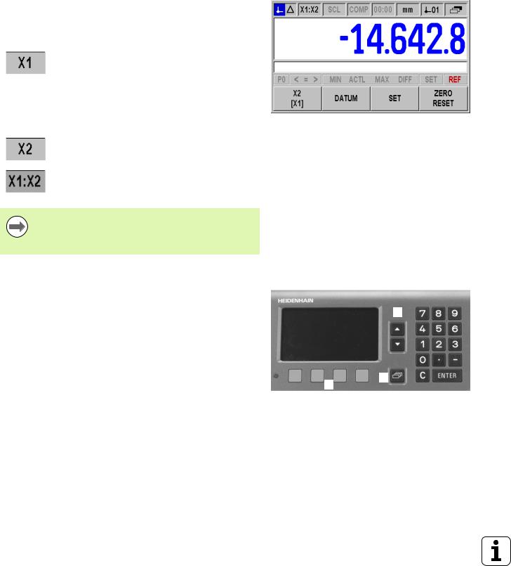
Data input
Use the keypad to enter numeric values within each field.
TheENTERkeywillconfirmtheentrywithinafieldandreturntothe previous screen.
Press the C key to clear entries, acknowledge error messages or return to the previous screen.
Soft-key labels 1showthevariousoperatingandparameter-setting functions. These functions are selected by pressing the corresponding soft key directly below each soft key label. The soft-key functionsare usually arranged in up to three soft-key pages. Use the NAVIGATION key 2 to move through the soft-key pages (see below).
The NAVIGATION key 2 moves through the pages of available soft-key functions. The current page will be highlighted in the status bar at the top of the screen.
Use the UP or DOWN arrow key 3 to move between fields within a form or menu items (parameters) of a menu. The orientation of the cursor is such that it will return to the top once it has reached the bottom of the menu.
3
2
1
Fig. I.16 Data input
I – 3 Basic functions of the ND 287
ND 287 |
27 |

I – 3 Basic functions of the ND 287
Integrated help system
The integrated help system provides appropriate information and assistance in any situation (see Fig. I.17).
To call the integrated help system:
Press the HELP soft key.
Information relevant to the current operation will be displayed.
Use the UP or DOWN arrow keys or the PAGE UP or DOWN soft keys if the explanation is spread over more than one screen page.
To view information on another topic: |
|
|
Press the LIST OF TOPICS soft key to view the index of the help |
|
|
topics. |
Fig. I.17 Integrated help system |
|
Press the PART 1/[PART 2] soft key to call the extended help, which |
||
|
||
is available in exceptional cases. |
|
|
Press the UP or DOWN arrow key or the PAGE UP or PAGE DOWN |
|
|
soft key to scroll through the index. |
|
|
Press the VIEW TOPIC soft key or the ENTER key to select the item |
|
|
you need. |
|
|
To leave the integrated help system: |
|
|
Press the C key. The ND will return to the screen from which you |
|
|
called the help system. |
|
28 |
I Working with the ND 287 position display unit |
Data input forms
Information required for various operational functions and setup parameters is entered through a data input form. These forms will appear after selecting features that require any additional information. Each form provides specific fields for entering the required information.
To confirm the changes:Press the ENTER key.
To ignore the changes and return to the previous screen:Press the C key.
Instruction box messages
Whenever a menu or form is open, an instruction box will also open immediately to the right of it (see Fig. I.18). This message box will provide information to the operator on what the chosen function does and present instructions on the available options.
Fig. I.18 Example of instruction box messages
Error messages
If an error occurs while you are wo rking with the ND, the message will appear on the display and provide an explanation of what caused the error.
To acknowledge the error message:Press the C key.
If a new error occurs before the last error has been acknowledged, the last error that has occurred will be displayed. After the last error has been acknowledged, the previous error will be displayed again. The ND always stores the last error of each error category for acknowledgment (see "Error messages" on page 60).
I – 3 Basic functions of the ND 287
ND 287 |
29 |
I – 4 Job Setup
I – 4 Job Setup
Operating modes
The ND 287 has two operating modes: Actual Value and Distance-
To-Go.
Status bar |
Function |
Fig. I.19 Actual Value symbol (highlighted) in the |
|
Shows current actual position |
status display |
|
|
|
|
|
|
|
Displays current distance from the |
|
|
nominal position |
|
|
|
|
In the Actual Value operating mode, the ND 287 always displays the current actual position of the length gauge, relative to the active datum. In this mode, all moves are done by traveling until the display matches the nominal position that is required.
The Distance-To-Go feature enables you to approach nominal positions simply by traversing to display value zero. Proceed as follows:
Press the DELTA MODE ON soft key to switch the operating mode (see "Soft-key functions on the standard screen" on page 25): The display value is zero.
Use the numeric keys to enter the nominal position you want to move to and confirm with the ENTER key: The distance-to-go is displayed.
Traverse the axis until the display value is zero.
If required, enter the next nominal position and confirm with the ENTER key: Traverse the axis until the display value is zero.
To leave the Distance-To-Go operating mode: Press the DELTA MODE OFF soft key.
Algebraic sign of distance-to-go:
The distance-to-go has a positive sign if the axis direction from the actual toward s thenominalpositionis negative.
The distance-to-go has a negative sign if the axis direction from the actual toward s thenominalpositionis positive.
In the Distance-To-Go operating mode, the switching outputs A1 (pin 15) and A2 (pin 16) have a different function (see "Switching outputs at D-sub connection X41" on page 95).
30 |
I Working with the ND 287 position display unit |
Loading...