


User's Manual
POSITIP 855
December 2002
for Milling
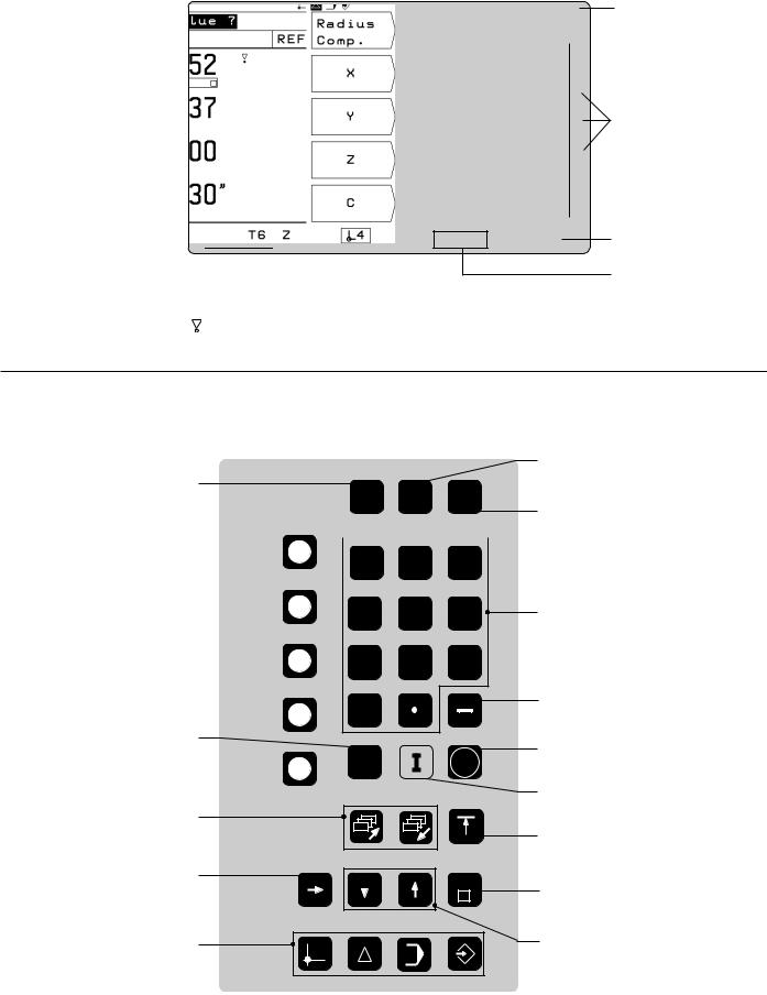
Screen
|
Operating |
|
Reference marks |
Operating mode |
|||||||||
|
mode or |
|
|
have been |
symbols (current |
||||||||
|
|
function |
|
|
crossed over |
|
mode is highlighted) |
|
|||||
Plain language |
|
|
|
|
|
|
|
|
Symbol for |
||||
|
|
|
|
|
|
|
|||||||
dialog line |
|
|
|
|
|
|
|
|
|
|
soft-key row |
||
|
|
|
|
|
|
|
|
||||||
Input line |
|
|
|
|
|
|
|
|
|
|
Soft-key row |
||
|
|
|
|
|
|
|
|
|
|
||||
|
|
|
|
|
|
|
|
|
|
||||
|
|
|
|
|
|
|
|
||||||
|
|
|
|
|
|
|
|
|
|
|
|
(with 5 soft |
|
Distance-to-go |
|
|
|
|
|
|
|
|
|
|
keys) |
||
|
|
|
|
|
|
|
|
|
|
|
|||
|
|
|
|
|
|
|
|
|
|
|
|||
display |
|
|
|
|
|
|
|
|
Soft keys |
||||
|
|
|
|
|
|
|
|
|
|
|
|
||
|
|
|
|
|
|
|
|
|
|
|
|
|
|
Feed rate 

Symbols
Behind the position display:
: Scaling factor or oversize active Æ: Diameter display
Datum
Tool number and tool axis
Keyboard
Change parameters |
|
and settings |
MOD INFO HELP |
5 soft keys 
 (functions vary accord- 7 8 9 ing to associated fields
on screen)
|
4 |
5 |
6 |
|
1 |
2 |
3 |
|
0 |
|
|
Clear entries or |
|
|
|
error messages |
CE |
|
ENT |
|
|
||
Page through |
|
|
|
individual screens |
|
|
|
Access program blocks to |
|
|
GOTO |
make changes, or switch |
|
|
|
|
|
|
|
operating parameters |
|
|
|
Select operating mode |
|
|
|
Select or deselect
INFO functions
Select or deselect HELP screens
Numeric input keys
Change sign
Confirm entry
Incremental dimensions
Return to previous soft-key row
Go to program block or operating parameter
Switch datum; select entry fields

Software version
This User's Manual is for POSITIP models with the following software version:
246 xxx-05.
The x's can be any numbers. The software version of your unit is shown on a label on the rear panel.
This User's Manual covers the functions of the POSITIP 855 for milling applications. For turning applications, a separate manual is available.
Location for use
This unit corresponds to class A in accordance with EN 55 022 and will be used predominantly in industrially zoned areas
About this manual
This manual is divided into two parts:
•Part I: Operating Instructions ... starts on page 5
•Part II: Technical Information ..... starts on page 81
Operating Instructions
When using the POSITIP in your work, you need only refer to the Operating Instructions (Part I).
If you're new to POSITIP, you can use the operating instructions as a step-by-step workbook. This part begins with a short introduction to the basics of coordinate systems and position feedback, and provides an overview of the available features. Each feature is explained in detail, using an example which you can immediately try out on the machine — so you won't get "lost" in the theory. As a beginner you should work through all the examples presented.
If you're already familiar with POSITIP, you can use the operating instructions as a comprehensive review and reference guide. The clear layout and the subject index make it easy to find the desired topics.
Technical Information
If you are interfacing POSITIP to a machine or wish to use the data interfaces, refer to the technical information in Part II.
Subject Index
A subject index for both parts of the manual can be found on pages 113 to 115.
POSITIP 855 |
Operating Instructions |

Dialog flowcharts
Dialog flowcharts are used for each example in this manual.
They are laid out as follows:
This area shows the |
This area explains the key function or work step. |
keys to press. |
If necessary, supplementary information will also be included. |
|
|
P r o m p t
This area shows the keys to press.
This area explains the key function or work step.
If necessary, supplementary information will also be included.
If there is an arrow at the end of the flowchart, this means that it continues on the next page.
A prompt appears with some actions (not always) at the top of the screen. In the flowcharts the prompts always have a gray background.
If two flowcharts are divided by a broken line, this means that you can follow the instructions either above or below the broken line.
Some flowcharts also show the screen that will appear after you press the correct keys.
Abbreviated flowcharts
Abbreviated flowcharts supplement the examples and explanations. An arrow ( ) indicates a new input or a work step.
Important Notes in this Manual
The surfaces marked gray contain especially important information. Please pay special attention to these notes.
Neglecting this information can result in e.g. functions not working in the desired way or in causing damage to the workpiece or to the tool.
Symbols within the notes
Every note is marked with a symbol on the left informing about the meaning of the note.
General Information,
e.g. on the behaviour of the POSITIP.
Important Information,
e.g. when a special tool is required for a function.
Electric Shock Warning, e.g. when opening a housing.
Operating Instructions |
POSITIP 855 |

|
Part I: Operating Instructions |
|
I - 1 |
Fundamentals of Positioning ...................................................... |
7 |
I - 2 Working with POSITIP – First Steps ......................................... |
13 |
|
|
Before you start ................................................................................................ |
13 |
|
Switch-on ......................................................................................................... |
13 |
|
Operating modes .............................................................................................. |
14 |
|
The HELP, MOD and INFO functions ................................................................ |
14 |
|
Selecting soft-key functions .............................................................................. |
15 |
|
On-screen operating instructions ....................................................................... |
16 |
|
Error messages ................................................................................................ |
17 |
|
Selecting the unit of measurement ................................................................... |
17 |
|
Selecting the angle format ................................................................................ |
17 |
|
Entering tool length and diameter ...................................................................... |
18 |
|
Calling the tool data .......................................................................................... |
19 |
|
Datum setting: Approaching positions and entering actual values ..................... |
20 |
|
Probing functions for datum setting ................................................................... |
22 |
|
Displaying and moving to positions ................................................................... |
29 |
I - 3 Hole Patterns and Rectangular Pocket .................................... |
35 |
|
|
Bolt hole circle patterns .................................................................................... |
35 |
|
Linear hole patterns .......................................................................................... |
39 |
|
Milling a rectangular pocket .............................................................................. |
43 |
I - 4 |
Programming POSITIP .............................................................. |
45 |
|
PROGRAMMING AND EDITING operating mode .............................................. |
45 |
|
Program number ............................................................................................... |
46 |
|
Deleting programs ............................................................................................. |
46 |
|
Editing programs ............................................................................................... |
47 |
|
Entering program blocks ................................................................................... |
48 |
|
Calling the tool data in a program...................................................................... |
50 |
|
Calling datum points ......................................................................................... |
50 |
|
Transferring positions: Teach-In mode .............................................................. |
51 |
|
Hole patterns in programs ................................................................................. |
56 |
|
Rectangular pocket milling in programs ............................................................ |
60 |
|
Enteringprograminterruptions .......................................................................... |
63 |
|
Subprograms and program section repeats ....................................................... |
64 |
|
Editing program blocks ..................................................................................... |
69 |
|
Deleting program blocks ................................................................................... |
70 |
|
Transferring programs over the data interface ................................................... |
71 |
I - 5 |
Executing Programs .................................................................. |
73 |
I - 6 The INFO Functions: |
|
|
|
Pocket Calculator, Stopwatch and Cutting Data Calculator .. |
75 |
|
To access the INFO functions ........................................................................... |
75 |
|
Cutting data: Calculate spindle speed S and feed rate F.................................... |
76 |
|
Stopwatch ........................................................................................................ |
77 |
|
Pocket calculator functions ............................................................................... |
77 |
I - 7 User Parameters: The MOD Function ...................................... |
79 |
|
|
Scaling factors .................................................................................................. |
79 |
|
Entering user parameters .................................................................................. |
80 |
Part II: Technical Information............................................................ |
81 |
|
Subject Index .................................................................................... |
113 |
|
I
Operating Instructions

I - 1 Fundamentals of Positioning
Fundamentals of Positioning
I - 1
Fundamentals of Positioning
You can skip over this chapter if you are familiar with the concepts of coordinate systems, incremental and absolute dimensions, nominal and actual positions, and distance-to-go.
Coordinate systems
In order to define positions on a surface, a reference system is required. For example, positions on the earth's surface can be defined absolutely by their geographic coordinates of longitude and latitude. The term coordinate comes from the Latin word for "that which is arranged." In contrast to the relative definition of a position that is referenced to a known location, the network of horizontal and vertical lines on the globe constitute an absolute reference system.
60°
Greenwich
30°
0°
30°
60°
90° 0° 90°
Fig. 1: The geographic coordinate system is an absolute reference system
On a milling machine equipped with a position display unit, workpieces are normally machined according to a workpiece-based Cartesian coordinate system (a rectangular coordinate system named after the French mathematician and philosopher Renatus Cartesius, who lived from 1596 to 1650). The Cartesian coordinate system is based on three coordinate axes designated X, Y and Z which are parallel to the machine guideways.
The figure to the right illustrates the "right-hand rule" for remembering the three axis directions: the middle finger is pointing in the positive direction of the tool axis from the workpiece toward the tool (the Z axis), the thumb is pointing in the positive X direction, and the index finger in the positive Y direction.
+Y |
+Z |
+X |
|
|
+X |
Fig. 2: Designations and directions of the axes on a milling machine
POSITIP 855 |
Operating Instructions |
7 |

I - 1 Fundamentals of Positioning
Fundamentals of Positioning
Setting the datum
The workpiece drawing identifies a certain point on the workpiece (usually a corner) as the “absolute datum” and perhaps one or more other points as relative datums. The datum setting procedure establishes these points as the origin of the absolute or relative coordinate systems: The workpiece, which is aligned with the machine axes, is moved to a certain position relative to the tool and the display is set either to zero or to another appropriate value (e.g., to compensate the tool radius).
Example:Drawing with several relative datums (ISO 129 or DIN 406 Part 11, fig. 171)
|
|
|
-250 |
-216,5 |
-125 |
0 |
125 |
216,5 |
250 |
|
|
|
|
|
|
|
|
|
|
216,5 |
250 |
|
|
|
|
|
|
|
|
|
|
|
|
|
|
|
|
|
|
|
|
125 |
|
1225 |
|
|
|
|
|
|
|
|
0 |
|
|
|
|
|
|
|
|
|
|
-125 |
|
|
|
150 |
|
|
|
|
|
|
-216,5 |
-250 |
|
|
|
|
|
|
|
|
|
|
|
750 |
|
0 |
|
|
|
|
|
|
|
|
|
|
|
|
|
|
|
|
|
|
|
|
300±0,1 |
-150 |
|
|
|
|
|
|
|
|
320 |
|
0 |
|
|
|
|
|
|
|
|
|
|
|
|
|
|
|
|
|
|
|
0 |
|
|
|
|
|
|
|
|
|
|
|
0 |
325 |
450 |
|
700 |
|
900 950 |
|
||
Z |
Y |
X |
Fig. 3: The workpiece datum represents the origin of the Cartesian coordinate system
Example: |
Coordinates of hole 1 : |
Z |
|
|
|
|
X = 10 |
mm |
|
|
|
|
|
|
|
||
|
Y = 5 |
mm |
|
|
|
|
Z = 0 |
mm (hole depth: Z = – 5 mm) |
|
|
|
|
The datum of the Cartesian coordinate system |
Y |
|
|
|
|
is located 10 mm from hole 1 in the X axis and |
|
|
|
|
|
5 mm from it in the Y axis (in negative direction). |
|
|
|
|
The KT Edge Finder from HEIDENHAIN, together with the |
|
|
X |
||
POSITIP'S edge finding functions, facilitates finding and setting |
|
|
1 |
||
datums. |
|
|
5 |
|
|
|
|
|
|
|
|
|
|
|
|
|
10 |
|
|
|
Fig. 4: Hole |
1 |
defines the coordinate system |
8 |
Operating Instructions |
POSITIP 855 |
I - 1 Fundamentals of Positioning
Fundamentals of Positioning
Nominal position, actual position and distance-to-go
The position that the tool is to move to is called the nominal position, while the position of the tool at any given moment is called the actual position. The distance from the nominal position to the actual position is called the distance-to-go.
Sign for distance-to-go
The distance-to-go has a positive sign if the axis direction from the actual towards the nominal position is negative.
The distance-to-go has a negative sign if the axis direction from the actual towards the nominal position is positive.
Absolute workpiece positions
Each position on the workpiece is uniquely identified by its absolute coordinates.
Example: Absolute coordinates of position 1 :
X |
= |
20 |
mm |
Y |
= |
10 |
mm |
Z |
= |
15 |
mm |
If you are drilling or milling a workpiece according to a workpiece drawing with absolute coordinates, you are moving the tool to the value of the coordinates.
Incremental workpiece positions
A position can also be referenced to the preceding nominal position. In this case the relative datum is always the last programmed position. Such coordinates are referred to as incremental coordinates (increment = increase). They are also called incremental or chain dimensions (since the positions are defined as a chain of dimensions). Incremental coordinates are designated with the
prefix I.
Example: Incremental coordinates of position 3 referenced to position 2
Absolute coordinates of position 2 :
X |
= |
10 |
mm |
Y |
= |
5 |
mm |
Z |
= |
20 |
mm |
Incremental coordinates of position 3 :
IX= |
10 |
mm |
IY= |
10 |
mm |
IZ = |
–15 |
mm |
If you are drilling or milling a workpiece according to a drawing with incremental coordinates, you are moving the tool by the value of the coordinates.
An incremental position definition is therefore a specifically relative definition. Likewise, a position defined by the distance-to-go to the nominal position is also a relative position (in this case the relative datum is in the nominal position).
Z |
S |
I |
R |
Y |
X |
Fig. 5: Nominal position S , actual position I and distance-to-go R
|
Z |
|
|
|
|
|
|
1 |
|
Y |
|
|
|
|
15 |
|
Z=15mm |
|
|
|
|
Y=10mm |
X |
|
|
X=20mm |
|
||
|
|
|
||
|
|
|
|
|
10 |
|
|
|
|
|
|
|
|
20 |
Fig. 6: Position definition through absolute coordinates
|
|
3 |
|
Y |
|
|
I |
|
15mm–Z=I |
Y |
|
2 |
= |
||
1 |
|||
|
0 |
||
|
|
m |
|
|
|
m |
|
20 |
|
IX=10mm |
|
|
|
|
|
10 |
15 |
|
X |
|
|
||
|
|
|
|
5 |
5 |
|
10 |
|
|
|
|
0 |
|
|
10 |
|
|
|
|
|
0 |
|
|
Fig. 7: Position definition through incremental coordinates
POSITIP 855 |
Operating Instructions |
9 |
I - 1 Fundamentals of Positioning
Fundamentals of Positioning
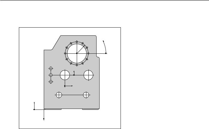
Example: Workpiece drawing with coordinate dimensioning (ISO 129 or DIN 406 part 11, fig. 179)
|
3.5 |
3.4 |
3.3 |
|
|
|
ϕ |
||
|
3.6 |
r |
3.2 |
|
|
|
|
||
|
3.7 |
|
3.1 |
|
|
3 |
|
|
|
|
|
|
|
|
|
3.8 |
|
3.12 |
|
2.1 |
3.9 |
3.10 |
3.11 |
|
|
|
|
|
|
2.2 |
2 |
Y2 |
1.3 |
|
|
|
|||
2.3 |
|
|
|
|
|
|
X2 |
|
|
|
1.1 |
|
1.2 |
|
Y1
1
 X1
X1
A coordinate list corresponding to this example is useful when working in the PROGRAMMING AND EDITING operating mode.
|
|
|
Dimensions in mm |
|
|
|
|
|
||
|
Coordinate |
|
Coordinates |
|
|
|
|
|
||
|
|
|
|
|
j |
|
|
|
|
|
|
|
|
|
|
|
|
|
|
||
|
origin |
Pos. |
X1 X2 |
Y1 Y2 |
r |
d |
|
|
|
|
|
|
|
|
|
|
|
|
|
|
|
|
1 |
1 |
0 |
0 |
|
|
– |
|
|
|
|
|
|
|
|
|
|
|
|
|
|
|
1 |
1.1 |
325 |
320 |
|
|
Æ |
120 |
H7 |
|
|
|
|
|
|
|
|
|
|
|
|
|
1 |
1.2 |
900 |
320 |
|
|
Æ |
120 |
H7 |
|
|
|
|
|
|
|
|
|
|
|
|
|
1 |
1.3 |
950 |
750 |
|
|
Æ |
200 |
H7 |
|
|
|
|
|
|
|
|
|
|
|
|
|
1 |
2 |
450 |
750 |
|
|
Æ |
200 |
H7 |
|
|
|
|
|
|
|
|
|
|
|
|
|
1 |
3 |
700 |
1225 |
|
|
Æ |
400 |
H8 |
|
|
|
|
|
|
|
|
|
|
|
|
|
2 |
2.1 |
– 300 |
150 |
|
|
Æ |
50 |
H11 |
|
|
|
|
|
|
|
|
|
|
|
|
|
2 |
2.2 |
– 300 |
0 |
|
|
Æ |
50 |
H11 |
|
|
|
|
|
|
|
|
|
|
|
|
|
2 |
2.3 |
– 300 |
– 150 |
|
|
Æ |
50 |
H11 |
|
|
|
|
|
|
|
|
|
|
|
|
|
3 |
3.1 |
|
|
250 |
0° |
Æ |
26 |
|
|
|
|
|
|
|
|
|
|
|
|
|
|
3 |
3.2 |
|
|
250 |
30° |
Æ |
26 |
|
|
|
|
|
|
|
|
|
|
|
|
|
|
3 |
3.3 |
|
|
250 |
60° |
Æ |
26 |
|
|
|
|
|
|
|
|
|
|
|
|
|
|
3 |
3.4 |
|
|
250 |
90° |
Æ |
26 |
|
|
|
|
|
|
|
|
|
|
|
|
|
|
3 |
3.5 |
|
|
250 |
120° |
Æ |
26 |
|
|
|
|
|
|
|
|
|
|
|
|
|
|
3 |
3.6 |
|
|
250 |
150° |
Æ |
26 |
|
|
|
|
|
|
|
|
|
|
|
|
|
|
3 |
3.7 |
|
|
250 |
180° |
Æ |
26 |
|
|
|
|
|
|
|
|
|
|
|
|
|
|
3 |
3.8 |
|
|
250 |
210° |
Æ |
26 |
|
|
|
|
|
|
|
|
|
|
|
|
|
|
3 |
3.9 |
|
|
250 |
240° |
Æ |
26 |
|
|
|
|
|
|
|
|
|
|
|
|
|
|
3 |
3.10 |
|
|
250 |
270° |
Æ |
26 |
|
|
|
|
|
|
|
|
|
|
|
|
|
|
3 |
3.11 |
|
|
250 |
300° |
Æ |
26 |
|
|
|
|
|
|
|
|
|
|
|
|
|
|
3 |
3.12 |
|
|
250 |
330° |
Æ |
26 |
|
|
|
|
|
|
|
|
|
|
|
|
|
|
|
|
|
|
|
|
|
|
|
|
10 |
Operating Instructions |
POSITIP 855 |

I - 1 Fundamentals of Positioning
Fundamentals of Positioning
Position feedback
The position feedback encoders convert the movement of the machine axes into electrical signals. The POSITIP constantly evaluates these signals and calculates the actual positions of the machine axes, which it displays as a numerical value on the screen.
If there is an interruption in power, the calculated position will no longer correspond to the actual position. When power is restored, you can re-establish this relationship with the aid of the reference marks on the position encoders and the POSITIP's reference mark evaluation feature (REF).
Reference marks
The scales of the position encoders contain one or more reference marks. When a reference mark is passed over, it generates a signal which identifies that position as the reference point (scale reference point = machine reference point). With the aid of this reference mark the POSITIP's REF feature re-establishes the assignment of displayed positions to machine axis positions which you last defined by setting the datum.
If the position encoders featuredistance-coded reference marks, each axis needs only move a maximum of 20 mm (0.8 in.) for linear encoders, and 20° for angle encoders.
Angle reference axis
For angular positions, the following reference axes are defined:
Plane |
Angle reference axis |
X Y |
+X |
|
|
Y Z |
+Y |
|
|
Z X |
+Z |
|
|
Positive direction of rotation is counterclockwise if the working plane is viewed in negative tool axis direction (see fig. 10).
Example: Angle in the working plane X / Y
Angle |
Corresponds to the... |
|
+ |
45° |
... bisecting line between +X and +Y |
|
|
|
+/– |
180° |
... negative X axis |
|
|
|
– |
270° |
... positive Y axis |
|
|
|
Z |
Y |
X |
Fig. 8: Linear position encoder, here for the X axis
Fig. 9: Linear scales: with distance-coded reference marks (upper illustration) and one reference mark (lower illustration)
Y |
–270° |
+45° |
+180° |
X |
–180° |
Fig. 10: Angle and the angle reference axis, e.g. in the X / Y plane
POSITIP 855 |
Operating Instructions |
11 |

I - 1 Fundamentals of Positioning
Fundamentals of Positioning
NOTES
12 |
Operating Instructions |
POSITIP 855 |
I - 2 Working with POSITIP – First Steps
I - 2
Working with POSITIP – First Steps
Before you start
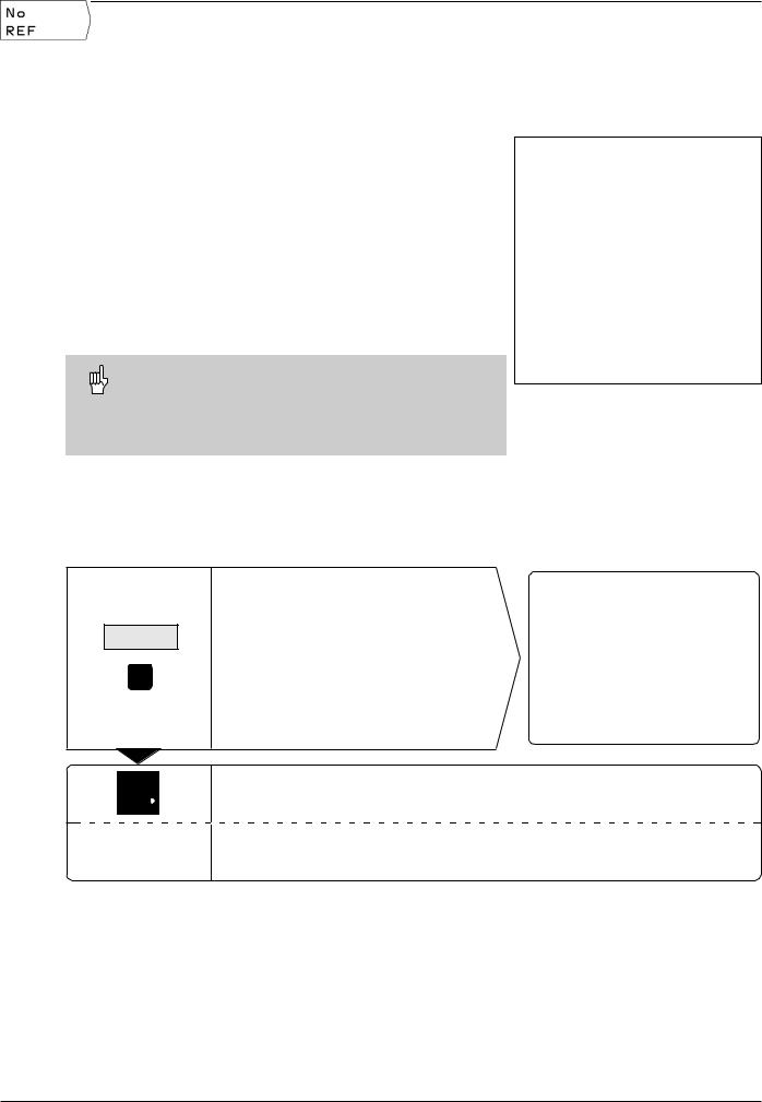
You can cross over the reference marks after every switch-on.
The POSITIP's reference mark evaluation feature (REF) automatically re-establishes the relationship between axis slide positions and display values that you last defined by setting the datum.
When you have crossed over all the reference marks, the REF indicator appears in the input line at the top of the screen.
Setting new datum points automatically stores the new relationship between axis positions and display values.
Working without reference mark evaluation
You can also use the POSITIP without crossing over the reference marks — simply press the soft key No REF.
Note that if you do not cross over the reference marks, POSITIP does not store the datum points. This means that it is not possible to re-establish the relationship between axis slide positions and display values after a power interruption (switch-off).
Fig. 11: REF display on screen
Switch-on
0 ä 1
Switch on the power and
press any key.
Cross over the reference marks in all axes (in any order).
Do not cross over the reference marks.
Note: In this case the relationship between axis slide positions and display values will be lost after a power interruption.
Your POSITIP is now ready for operation and is in the ACTUAL VALUE operating mode.
POSITIP 855 |
Operating Instructions |
13 |
I - 2 Working with POSITIP – First Steps
Operating modes
Selecting the operating mode determines which functions are available to you.
|
Available functions |
Mode |
Key |
|
|
Position display for |
ACTUAL VALUE |
|
|
|
workpiece machining; |
|
|
|
|
Zero reset; |
|
|
|
|
Datum setting |
|
|
|
|
– also with edge finder |
|
|
|
|
|
|
|
|
|
Distance-to-go display; hole |
DISTANCE- |
|
|
|
patterns; rectangular pocket; |
TO-GO |
|
|
|
drilling and milling with tool radius compensation |
|
|
|
|
|
|
|
|
|
Storage of work steps for |
PROGRAMMING |
|
|
|
small-lot production |
AND EDITING |
|
|
|
|
|
|
|
|
Run programs previously |
EXECUTE |
|
|
|
created in the PROGRAMMING |
PROGRAM |
|
|
|
AND EDITING mode |
|
|
|
|
|
|
|
|
You can switch to another operating mode at any time by pressing the key for the desired mode.
The HELP, MOD and INFO functions
You can call the HELP, MOD and INFO functions at any time.
To call a function:
ä Press the function key for that function.
Toleavethe function:
ä Press the same function key again.
Available functions |
Mode |
Key |
|
|
|
|
|
On-screen operating |
HELP |
instructions: graphics and |
|
text keyed to the current |
|
screen contents |
|
HELP
User parameters: |
MOD |
To redefine POSITIP's basic |
|
operating characteristics |
|
MOD
Cutting data calculator, |
INFO |
stopwatch, pocket calculator |
|
INFO
14 |
Operating Instructions |
POSITIP 855 |

I - 2 Working with POSITIP – First Steps
Selecting soft-key functions
The soft-key functions are grouped into one or more rows. POSITIP indicates the number of rows by a symbol at the upper right of the screen. If no symbol is shown, that means there is only one row for the function. The highlighted rectangle in the symbol indicates the current row.
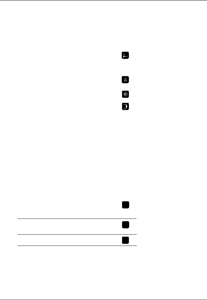
Function |
Key |
|
|
Page throught soft-key rows: forwards
Page through soft-key rows: backwards
Go back one level
POSITIP displays the soft keys with the main functions of an operating mode whenever you press the key for that mode.
Fig. 12: The symbol for soft-key row is at the top right of the screen. Here, the second row is being displayed.
POSITIP 855 |
Operating Instructions |
15 |

I - 2 Working with POSITIP – First Steps
On-screen operating instructions
The integrated operating instructions provide information and assistance in any situation.
To call the operating instructions:
äPress the HELP key.
äUse the paging keys if the explanation is spread over more than one screen page.
To leave the operating instructions: äPress the HELP key again.
Example: On-screen operating instructions for datum setting with the edge finder (PROBE CIRCLE CENTER)
The PROBE CIRCLE CENTER function is described in this manual on page 25.
äSelect the ACTUAL VALUE operating mode.
äPress the Probe soft key.
Press the HELP key.
The first page of the operating instructions for the Probe function appears.
Page reference at the lower right of the screen:
the number in front of the slash is the current page, the number behind the slash is the total number of pages.
The on-screen operating instructions now contains the following information on ACTUAL VALUE – PROBE (on three pages):
•Overview of the probing functions (page 1)
•Graphic illustration of all probing functions (pages 2 and 3)
äTo leave the operating instructions: Press HELP again.
The screen returns to the selection menu for the probing functions.
äPress (for example) the soft key Circle Center.
äPress HELP.
The screen now displays operating instructions – spread over
five pages – on the PROBE CIRCLE CENTER function including:
•Overview of all work steps (page 1)
•Graphic illustration of the probing sequence (page 2)
•Information on how POSITIP reacts and on datum setting (page 3)
•Probing function Circle Center for tools (pages 4 and 5)
äTo leave the on-screen operating instructions: Press HELP.
Fig. 13:On-screen operating instructions for
PROBE CIRCLE CENTER, page 1
Fig. 14: On-screen operating instructions for
PROBE CIRCLE CENTER, page 2
Fig. 15: On-screen operating instructions for
PROBE CIRCLE CENTER, page 3
16 |
Operating Instructions |
POSITIP 855 |
I - 2 Working with POSITIP – First Steps
Error messages
If an error occurs while you are working with POSITIP, a message will come up on the screen in plain English.
To call an explanation of the error: ä Press the HELP key.
To clear the error message: ä Press the CE key.
Blinking error messages
W A R N I N G
Blinking error messages mean that the operational reliability of the POSITIP has been impaired.
If a blinking error message occurs:
ä
ä
ä
ä
Note down the error message displayed on the screen. Switch off the power to the POSITIP.
Attempt to correct the problem with the power off.
If the blinking error message recurs, notify your customer service agency.
Selecting the unit of measurement
Positions can be displayed in millimeters or inches. If you choose inches, inch will be displayed at the top of the screen next to
REF.
To change the unit of measurement: ä Press MOD.
ä Page to the soft key row containing the user parameter
mm or inch.
ä Choose the soft key mm or inch to change to the other unit. ä Press MOD again.
For more information on user parameters, see chapter I - 7.
Selecting the angle format |
|
Angles – such as for a rotary table – can be displayed either as a |
|
Fig. 16: The inch indicator |
|
decimal value or in degrees, minutes and seconds. |
|
To change the angle format:
äPress MOD.
äGo to the soft key row containing the user parameter
Deg/Min/Sec or Degrees decimal.
ä Choose the soft key Deg/Min/Sec or degrees decimal to change to the other format.
ä Press MOD again.
For more information on user parameters, see chapter I - 7.
POSITIP 855 |
Operating Instructions |
17 |

I - 2 Working with POSITIP – First Steps
MOD
Entering tool length and diameter
Enter the lengths and diameters of your tools in the POSITIP's tool table. You can enter up to 99 tools.
Before you start machining workpieces, select the tool you are using from the tool table. POSITIP will then take into account the entered diameter and length of the tool.
The tool length is the difference in length DL between the tool and the zero tool.
Sign for the length difference DL
If the tool is longer than the zero tool: DL > 0 If the tool is shorter than the zero tool: DL < 0
Z |
|
|
T1 |
T2 |
T3 |
D1 |
D2 |
D3 |
|
|
∆L3<0 |
∆L1=0 |
|
X |
|
∆L2>0 |
Example: Entering the tool length and diameter into the tool table
Tool number |
7 |
Tool axis |
Z |
Tool diameter |
D = 8 mm |
Tool length |
L = 12 mm |
Fig. 17: Tool length and diameter
Z |
|
T0 |
T7 |
|
D7 |
L0=0 |
X |
L7>0 |
MOD
Select the user parameters.
/ |
|
Go to the soft key row which has Tool Table. |
|
|
Open the tool table. |
|
T o o l n u m b e r ? |
|
7 |
ENT |
Enter the tool number (such as 7) and confirm your entry with ENT. |
Go to the column with Diameter.
T o o l d i a m e t e r ?
8 ENT |
Enter the tool diameter (such as 8 mm) and confirm your entry with ENT. |
18 |
Operating Instructions |
POSITIP 855 |
I - 2 Working with POSITIP – First Steps
MOD
T o o l l e n g t h ?
1 2 ENT
Enter the tool length (12 mm) and confirm your entry with ENT.
Select the tool axis (Z).
MOD
Depart the user parameters.
Calling the tool data
The lengths and diameters of your tools must first be entered into the POSITIP's tool table (see previous page).
Before you start workpiece machining, select the tool you are using from the tool table. POSITIP then takes into account the stored tool data when you work with tool compensation (e.g., with hole patterns).
You can also call the tool data with the command
TOOL CALL in a program.
|
|
Fig. 18: The tool table on the POSITIP's screen |
Calling the tool data |
|
|
MOD |
|
Select the user parameters. |
|
||
/ |
|
Go to the first soft key row which has Tool Table. |
|
||
|
||
|
|
Select the tool table. |
|
|
|
|
|
|
|
|
|
T o o l n u m b e r ?
5 |
ENT |
Enter the tool number (here: 5) and confirm your entry with ENT. |
The number of the selected tool appears at the bottom of the screen. |
||
|
|
|
|
|
|
MOD
Depart the user parameters.
POSITIP 855 |
Operating Instructions |
19 |

I - 2 Working with POSITIP – First Steps
Datum setting: Approaching positions and entering actual values
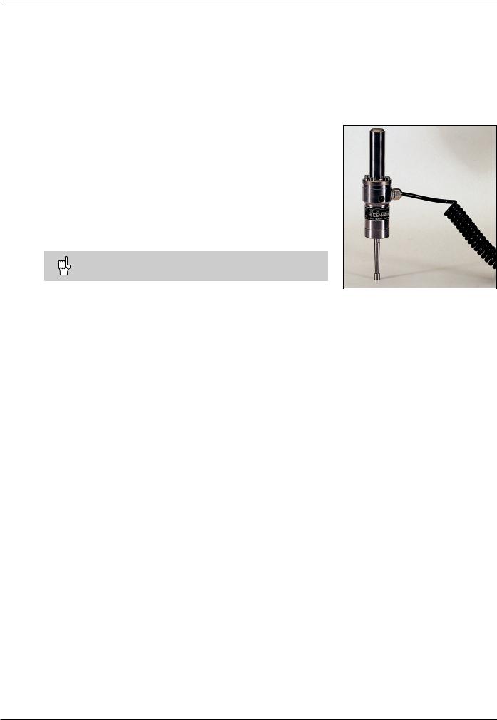
The easiest way to set datum points is to use the POSITIP's probing functions – regardless of whether you probe the workpiece with the HEIDENHAIN KT Edge Finder or with a tool. A description of the probing functions starts on page 22.
Of course, you can also set datum points in the conventional manner by touching the edges of the workpiece one after the other with the tool and entering the tool positions as datum points (see examples on this page and the next).
The datum table can hold up to 99 datum points. In most cases this will free you from having to calculate the axis travel when working with complicated workpiece drawings containing several datums.
For each datum point, the datum table contains the positions that the POSITIP assigned to the reference points on the scales (REF values) during datum setting. Note that if you change the REF values in the table, this will move the datum point.
Example: Setting a workpiece datum without the probing function
Z
Working plane: |
X |
/ |
Y |
|
|
|
|
|||
Tool axis: |
Z |
|
|
|
|
|
|
|
|
|
|
|
|
|
|
|
|
|
|
||
Tool radius: |
R = 5 mm |
|
|
|
|
|
|
|
||
|
|
|
|
|
|
|
||||
Axis sequence in |
|
|
Y |
|
|
|
|
|
|
|
|
|
|
|
|
|
|
|
|
||
|
|
|
|
|
|
|
|
|
||
|
|
|
|
|
|
|
|
|
|
|
this example: |
X |
- |
Y - Z |
|
|
|
|
|||
|
X |
|
Preparation: Select the datum |
1 |
|
2 |
||
Select the datum with the vertical arrow keys. |
||
|
||
POSITIP displays the number of the current datum at the lower right |
|
|
of the screen. |
|
Preparation: Call the tool data
Call the tool data for the tool which you are using to touch the workpiece (see previous page).
20 |
Operating Instructions |
POSITIP 855 |

I - 2 Working with POSITIP – First Steps
Datum setting: Approaching positions and entering actual values
Operating mode: ACTUAL VALUE
Touch edge 1 with the tool.
Select the X axis.
D a t u m S e t t i n g
X = + 0
5Enter the position of the tool center (X = – 5 mm) and
ENT |
transfer the X coordinate of the datum. |
|
Touch the workpiece at edge 2 . |
|
Select the Y axis. |
D a t u m S e t t i n g
Y = + 0
5Enter the position of the tool center (Y = – 5 mm) and
ENT |
transfer the Y coordinate of the datum. |
|
Touch the workpiece surface. |
|
|
Select the Z axis. |
|
|
|
D a t u m S e t t i n g |
||
Z |
= + 0 |
|
0 |
|
Enter the position of the tool tip (Z = 0 mm) |
|
||
|
|
and |
ENT |
|
transfer the Z coordinate of the datum. |
|
|
|
POSITIP 855 |
Operating Instructions |
21 |
I - 2 Working with POSITIP – First Steps
Probing functions for datum setting
The POSITIP's probing functions enable you to set datum points with a HEIDENHAIN KT Edge Finder. The probing functions are also available when you are using a tool instead of an edge finder.
Datum setting with the edge finder
It is particularly easy to set datum points with a HEIDENHAIN
KT Edge Finder. The following probing functions are available:
•Workpiece edge as datum:
Edge
•Centerline between two workpiece edges:
Centerline
•Center of a hole or cylinder:
Circle Center
With Circle Center, the hole must be in a main plane. The three main planes are formed by the axes X / Y, Y / Z and Z / X.
The HEIDENHAIN KT 120 Edge Finder can only be used with electrically conductive workpieces.
Preparation: Enter the stylus diameter and select the datum |
Fig. 19: The HEIDENHAIN KT Edge Finder |
äPress MOD and go to the soft key row containing the soft key
Edge Finder.
äSelect the user parameter Edge Finder.
äEnter the diameter of the edge finder stylus and confirm with ENT.
äSelect the user parameter Datum.
äEnter the number of the desired datum and confirm with ENT.
äPress MOD again.
The number of the selected datum is now shown at the lower right of the screen.
In all probing functions, POSITIP takes into account the entered stylus diameter.
For more information on user parameters, see chapter I - 7.
Exiting the probing function
While the probing function is active, POSITIP displays the soft key Escape. Choose this soft key to return to the opening state of the selected probing function.
22 |
Operating Instructions |
POSITIP 855 |
I - 2 Working with POSITIP – First Steps
Probing functions for datum setting
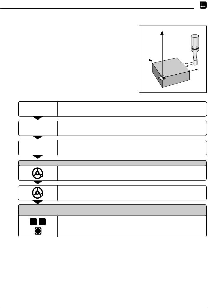
Example: Probe workpiece edge, display position of workpiece |
|
edge and set the edge as a datum |
Z |
The probed edge lies parallel to the Y axis.
The coordinates of the datum can be set by probing edges or sur- |
|
faces and capturing them as datums as described on the next |
Y |
page. |
X? |
X |
Operating mode: ACTUAL VALUE
Select Probe.
Select Edge.
Select axis for which the coordinate is to be set: X axis.
P r o b e i n X a x i s
Move the edge finder towards the workpiece edge until the
LEDs on the edge finder light up.
The position of the edge on the X axis is displayed on the screen.
Retract the edge finder from the workpiece.
|
E n t e r v a l u e f o r X |
||
|
|
+ 0 |
|
2 |
0 |
0 is offered as a default value for the coordinate. |
|
Enter the desired coordinate for the workpiece edge, for example X = 20 mm |
|||
|
|
||
ENT
and
set the coordinate as a datum for this workpiece edge.
POSITIP 855 |
Operating Instructions |
23 |
I - 2 Working with POSITIP – First Steps
Probing functions for datum setting
Example:Set centerline between two workpiece edges as datum |
|
|
|
The position of the centerline M is determined by probing the |
Z |
|
|
|
|
||
edges 1 and 2 . |
|
|
|
The centerline is parallel to the Y axis. |
|
|
|
Desired coordinate |
|
Y |
2 |
|
|
||
of the centerline: |
X = 5 mm |
|
|
|
|
||
|
|
1 |
M |
|
|
|
X? |
|
|
|
X |
Operating mode: ACTUAL VALUE |
|
|
|
|
Select Probe. |
|
|
Select Centerline.
Select the axis for which the coordinate is to be set: X axis.
P r o b e 1 s t e d g e i n X
Move the edge finder toward workpiece edge 1 until the LEDs in the edge finder light up.
P r o b e 2 n d e d g e i n X
Move the edge finder toward workpiece edge 2 until the LEDs in the edge finder light up. The display is frozen and the distance between the two edges appears under the selected axis.
Retract the edge finder from the workpiece.
5
ENT
E n t e r v a l u e f o r X + 0
Enter coordinate (X = 5 mm) and
transfer coordinate as datum for the centerline.
24 |
Operating Instructions |
POSITIP 855 |
I - 2 Working with POSITIP – First Steps
Probing functions for datum setting
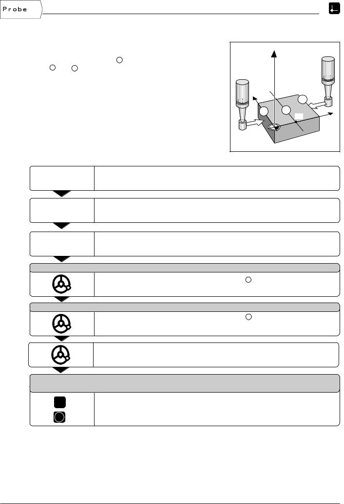
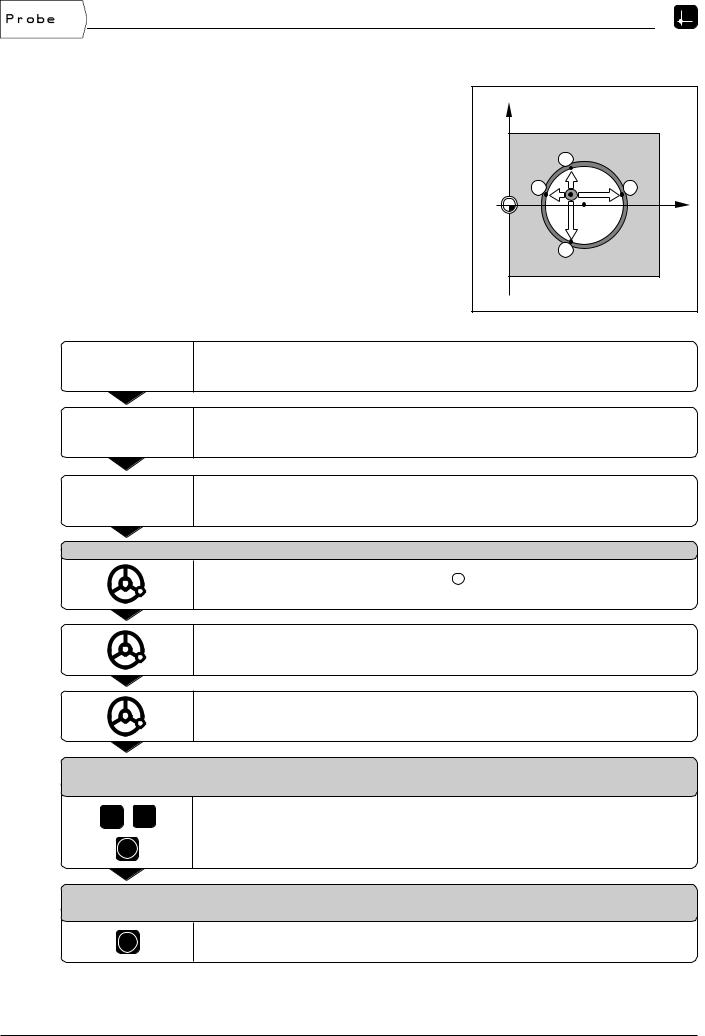
Example: Probe the circumference of a hole with an edge finder |
|
|
|
|
and set the center of the hole as a datum |
Y |
|
|
|
Main plane |
X / Y |
|
|
|
Edge finder axis |
parallel to the Z axis |
|
2 |
|
X coordinate of the |
|
|
|
|
circle center |
X = 50 mm |
3 |
|
4 |
Y coordinate of the |
|
0 |
X? |
X |
circle center |
Y = 0 mm |
|
||
|
|
|||
|
|
|
1 |
|
Operating mode: ACTUAL VALUE |
|
|
|
|
|
Select Probe. |
|
|
|
Select Circle Center.
Select plane containing the circle (main plane): Plane X/Y.
P r o b e 1 s t p o i n t i n X / Y
Move edge finder towards first point 1 on the circumference until the LEDs on the edge finder light up.
Retract edge finder from bore hole wall.
Probe three additional points on the circumference in the same manner.
Further instructions appear on the screen.
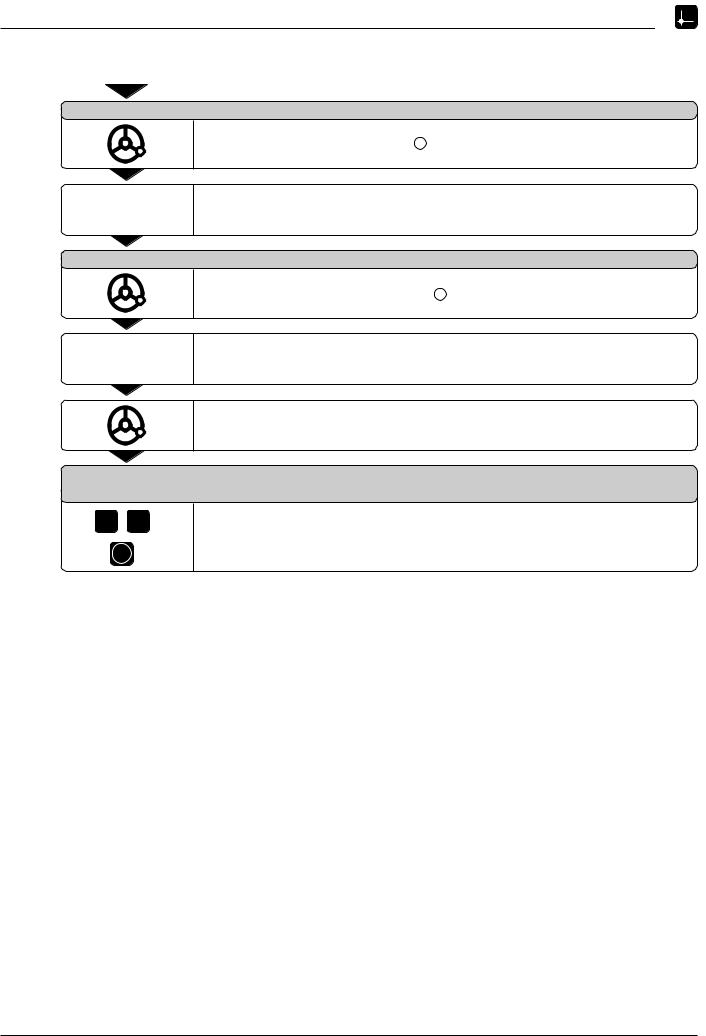
E n t e r c e n t e r p o i n t X
X = 0
5 0 |
Enter the first coordinate (X = 50 mm) |
|
and |
ENT |
transfer coordinate as datum for the circle center. |
E n t e r c e n t e r p o i n t Y
Y = 0
ENT
Accept default entry Y = 0 mm.
POSITIP 855 |
Operating Instructions |
25 |

I - 2 Working with POSITIP – First Steps
Probing functions for datum setting
Datum setting with a tool
Even if you use a tool to set datum points, you can still use POSITIP's probing functions described under the section "Datum setting with the edge finder" (Edge, Centerline and Circle
Center).
Preparation: Enter the tool diameter and select the datum
äPress MOD and go to the soft key row containing the soft key Tool Table.
ä
ä
ä
Select the user parameter Tool Table. Select the tool you will use to set the datum.
Leave the tool table: Press MOD again.
äUse the vertical arrow keys to select the number of the desired datum. The number of the selected datum is shown at the lower right of the screen.
Fig. 20: On-screen operating instructions for probing with a tool
Example: Set centerline between two probed edges as datum
The centerline is parallel to the Y axis. |
Z |
|
Desired coordinate |
|
|
of the centerline: |
X = 50 mm |
|
|
Y |
2 |
|
|
|
|
1 |
M |
|
|
X? |
|
|
X |
Operating mode: ACTUAL VALUE
Select Probe.
Select Centerline.
Select axis for which the coordinate is to be set: X axis.
26 |
Operating Instructions |
POSITIP 855 |
I - 2 Working with POSITIP – First Steps
Probing functions for datum setting
P r o b e 1 s t e d g e i n X
Touch the first workpiece edge 1 .
Store the position of the edge.
P r o b e 2 n d e d g e i n X
Touch the second workpiece edge 2 .
Store the position of the edge.
POSITIP displays the distance between the two edges.
|
|
Retract the tool from the workpiece. |
|
E n t e r v a l u e f o r X |
|
|
|
+ 0 |
5 |
0 |
Enter coordinate (X = 50 mm) |
|
|
and |
ENT |
|
transfer coordinate as datum for the centerline. |
POSITIP 855 |
Operating Instructions |
27 |

I - 2 Working with POSITIP – First Steps
NOTES
28 |
Operating Instructions |
POSITIP 855 |
 Loading...