


 Loading...
NC Software 280 620-xx 280 621-xx 286 180-xx
User’s Manual
Conversational
Programming
English (en)
4/2001

Controls on the visual display unit
Split screen layout
Switch between machining or programming modes
Soft keys for selecting functions in screen
Switching the soft-key rows
Changing the screen settings (only BC 120)
Typewriter keyboard for entering letters and symbols
File names Comments
ISO programs
Machine operating modes
MANUAL OPERATION
INCREMENTAL JOG
POSITIONING WITH MDI
PROGRAM RUN, SINGLE BLOCK
PROGRAM RUN, FULL SEQUENCE
Programming modes
PROGRAMMING AND EDITING
TEST RUN
Program/file management, TNC functions
Select programs and files
Delete programs and files (only TNC 406) Activate external data transfer (only TNC 406) Pocket calculator
Moving the highlight, going directly to blocks, cycles and parameter functions
Move highlight
Go directly to blocks, cycles and parameter functions
Override control knobs for feed rate/C axis
|
100 |
|
100 |
50 |
150 |
50 |
150 |
|
F % |
|
S % |
|
0 |
|
0 |
Programming path movements
Straight line
Circle center/pole for polar coordinates
Circle with center
Circle with radius
Circular arc with tangential connection
Corner rounding
Electrode data
Enter and call electrode length and radius Activate electrode radius compensation
Cycles, subprograms and program section repeats
Define and call cycles
Enter and call labels for subprogramming and program section repeats
Program stop in a program
Enter touch probe functions in a program
Coordinate axes and numbers:Entering and editing
Select coordinate axes or
. . . enter them into the program
. . . Numbers
Decimal point
Change arithmetic sign
Polar coordinates
Incremental dimensions
Q parameters
Capture actual position
Skip dialog questions, delete words
Confirm entry and resume dialog
End block
Clear numerical entry or TNC error message
Abort dialog, delete program section
TNC Models, Software and Features
This manual describes functions and features provided by the TNCs as of the following NC software numbers.
TNC Model |
NC Software No. |
TNC 406 |
280 620-12 |
|
280 621-12 |
|
280 622-12 |
|
|
TNC 416 |
286 180-06 |
|
|
Location of use
The TNC complies with the limits for a Class A device in accordance with the specifications in EN 55022, and is intended for use primarily in industrially-zoned areas.
New features of the NC software 280 62x-xx and 280 180-xx
Cycle 14 CONTOUR GEOMETRY (see also ”Cycle 14 CONTOUR GEOMETRY” on page 137)
Q parameters for the roughness (see also ”Data from the erosion table” on page 203)
Q parameters for the gap size (see also ”Gap size LS max when machining which Cycle 1 GENERATOR: Q164” on page 206)
After manual traverse, the incremental coordinates always refer to the actual position (see also ”Resuming program run with the GOTO key” on page 226)
Expansion of the tool table with tool pocket number, tool undersize and radius (see also ”Entering electrode data in tables” on page 74)
Probed values can be written to a datum table as well as to a tool table (see also ”Writing probed values to tables” on page 28)
Enhancement of functions FN14 and FN15 (see also ”Output of Q Parameters and Messages” on page 197)
M108/M109 (see Overview of Miscellaneous Functions on the inside rear cover of this manual)
HEIDENHAIN TNC 406, TNC 416 |
I |

Contents |
|
Introduction |
|
1 |
|
|
|||
|
|
|
||
|
|
|
2 |
|
|
|
Manual Operation, Setup and Probing |
|
|
|
|
|
|
|
|
|
Functions |
|
3 |
|
|
Positioning with manual data input |
|
|
|
|
|
|
|
|
|
(MDI) |
|
|
|
|
Programming: Fundamentals, Files, |
|
4 |
|
|
Program Entry, Spark Erosion, Erosion |
|
|
|
|
Tables |
|
|
|
|
Programming: Tools |
|
5 |
|
|
Programming: Programming Contours |
|
6 |
|
|
|
7 |
|
|
|
Programming: Miscellaneous Functions |
|
|
|
|
|
8 |
|
|
|
Programming: Cycles |
|
|
|
|
|
9 |
|
|
|
Programming: Subprograms and |
|
|
|
|
|
|
|
|
|
Program Section Repeats |
|
10 |
|
|
Programming: Q Parameters |
|
|
|
|
|
11 |
|
|
|
Test Run and Program Run |
|
|
|
|
|
12 |
|
|
|
MOD Functions |
|
|
|
|
|
13 |
|
|
|
Tables and Overviews |
|
|
|
|
|
|
|
|
|
|
|
|
HEIDENHAIN TNC 406, TNC 416 |
III |
.....1 Introduction |
1 |
|
|
|
|
1.1 The TNC 406, the TNC 416 ..... |
2 |
|
|||
Controls ..... |
2 |
|
|
|
|
Visual display unit and keyboard ..... |
2 |
||||
Programming ..... |
2 |
|
|
||
Graphics ..... |
2 |
|
|
|
|
|
Compatibility |
..... 2 |
|
|
|
|
|
|
1.2 |
Visual Display Unit and Keyboard |
..... 3 |
|
|
|
|||
|
Visual display unit ..... |
3 |
|
|
|
|
|
|
|
Screen layout |
..... 4 |
|
|
|
|
|
|
|
Keyboard ..... |
5 |
|
|
|
|
|
|
1.3 |
Modes of Operation ..... |
6 |
|
|
|
|
|
|
|
Manual Operation, Incremental Jog, and Positioning with Manual Data Input ..... |
6 |
||||||
|
Programming and Editing ..... |
|
7 |
|
|
|
||
|
Test Run ..... |
7 |
|
|
|
|
|
|
|
Program Run, Full Sequence and Program Run, Single Block ..... |
8 |
|
|||||
1.4 |
Status Display ..... |
9 |
|
|
|
|
|
|
|
General status display ..... |
9 |
|
|
|
|
||
|
Additional status displays |
..... |
9 |
|
|
|
||
1.5 |
Accessory: Electronic Handwheels from HEIDENHAIN ..... |
13 |
|
|
||||
|
HR electronic handwheels |
..... |
13 |
|
|
|
||
HEIDENHAIN TNC 406, TNC 416 |
I |
.....2 Manual Operation, Setup and Probing Functions |
15 |
|
|
||||||||
2.1 Switch-on ..... |
16 |
|
|
|
|
|
|
|
|
|
|
Switch-on ..... |
16 |
|
|
|
|
|
|
|
|
|
|
2.2 Moving the Machine Axes ..... |
|
18 |
|
|
|
|
|
|
|||
Note ..... |
18 |
|
|
|
|
|
|
|
|
|
|
To traverse with the machine axis direction buttons: ..... |
18 |
|
|
||||||||
Traversing with the HR 410 electronic handwheel |
..... 19 |
|
|
|
|||||||
Incremental jog positioning |
..... 20 |
|
|
|
|
|
|
||||
Positioning with manual data input (MDI) |
..... 20 |
|
|
|
|
||||||
Eroding a workpiece manually ..... |
21 |
|
|
|
|
|
|||||
2.3 Datum Setting ..... |
22 |
|
|
|
|
|
|
|
|
|
|
Example ..... |
|
22 |
|
|
|
|
|
|
|
|
|
2.4 Calibration and Setup ..... |
23 |
|
|
|
|
|
|
|
|
||
Using an electrode ..... |
23 |
|
|
|
|
|
|
|
|
||
Select the touch probe function ..... |
24 |
|
|
|
|
|
|||||
Calibrating the probing electrode ..... |
25 |
|
|
|
|
|
|||||
Compensating workpiece misalignment ..... |
27 |
|
|
|
|
||||||
2.5 Datum Setting with a Probing Electrode ..... |
28 |
|
|
|
|
||||||
Functions for setting the datum ..... |
28 |
|
|
|
|
|
|||||
Writing probed values to tables ..... |
28 |
|
|
|
|
|
|||||
Datum setting in any axis ..... |
|
29 |
|
|
|
|
|
|
|||
Manual probing ..... |
29 |
|
|
|
|
|
|
|
|
||
Workpiece center as datum ..... |
30 |
|
|
|
|
|
|||||
Corner as datum ..... |
31 |
|
|
|
|
|
|
|
|
||
Circle center as datum ..... |
32 |
|
|
|
|
|
|
||||
2.6 Measuring with a Probing Electrode ..... |
33 |
|
|
|
|
|
|||||
Introduction ..... |
33 |
|
|
|
|
|
|
|
|
|
|
To find the coordinate of a position on an aligned workpiece |
..... 33 |
||||||||||
Finding the coordinates of a corner in the working plane |
..... |
33 |
|||||||||
Measuring workpiece dimensions ..... |
34 |
|
|
|
|
|
|||||
Measuring angles ..... |
35 |
|
|
|
|
|
|
|
|
||
2.7 Entering and Starting Miscellaneous Functions M ..... |
36 |
|
|
|
|||||||
Entering values ..... |
36 |
|
|
|
|
|
|
|
|
||
.....3 Positioning with Manual Data Input (MDI) |
37 |
3.1 Positioning with Manual Data Input (MDI) ..... 38 |
|
Positioning with manual data input (MDI) ..... |
38 |
Protecting and erasing programs in $MDI ..... |
39 |
II
4 Programming: Fundamentals, Files, |
|
|
|
|
|
|
|||||
Program Entry, Spark Erosion, Erosion Tables |
..... 41 |
|
|
|
|||||||
4.1 Fundamentals of Positioning ..... |
42 |
|
|
|
|
|
|
||||
Introduction ..... |
42 |
|
|
|
|
|
|
|
|
|
|
What is NC? ..... |
42 |
|
|
|
|
|
|
|
|
|
|
The part program ..... |
42 |
|
|
|
|
|
|
|
|
||
Programming ..... |
42 |
|
|
|
|
|
|
|
|
|
|
Position encoders and reference marks ..... |
43 |
|
|
|
|
||||||
Reference system ..... |
43 |
|
|
|
|
|
|
|
|
||
Reference system with EDMs |
..... 44 |
|
|
|
|
|
|
||||
Programming electrode movement ..... |
44 |
|
|
|
|
|
|||||
Polar coordinates ..... |
45 |
|
|
|
|
|
|
|
|
||
Absolute and incremental workpiece positions ..... |
46 |
|
|
|
|||||||
Setting the datum ..... |
47 |
|
|
|
|
|
|
|
|
||
4.2 Files ..... |
48 |
|
|
|
|
|
|
|
|
|
|
File directory ..... |
48 |
|
|
|
|
|
|
|
|
|
|
Selecting, copying, deleting and protecting files ..... |
50 |
|
|
|
|||||||
4.3 Creating and Writing Programs ..... |
|
51 |
|
|
|
|
|
|
|||
Organization of an NC program in HEIDENHAIN conversational format. ..... |
51 |
||||||||||
Defining the blank form–BLK FORM ..... |
51 |
|
|
|
|
|
|||||
Creating a new part program ..... |
|
52 |
|
|
|
|
|
|
|||
Programming tool movements in conversational format ..... |
54 |
|
|||||||||
Editing a program ..... |
55 |
|
|
|
|
|
|
|
|
||
4.4 Automatic Workpiece Change with WP-Call ..... |
57 |
|
|
|
|
||||||
Programming a workpiece change ..... |
57 |
|
|
|
|
|
|||||
4.5 Fundamentals of Spark Erosion ..... |
|
58 |
|
|
|
|
|
|
|||
4.6 Erosion Tables ..... |
61 |
|
|
|
|
|
|
|
|
|
|
Using erosion tables in a program ..... |
61 |
|
|
|
|
|
|||||
Working without an erosion table ..... |
61 |
|
|
|
|
|
|||||
Ready-to-use erosion tables ..... |
|
61 |
|
|
|
|
|
|
|||
HEIDENHAIN TNC 406, TNC 416 |
III |
4.7 Parameters in the Erosion Table |
..... 62 |
|
|
||
To enter erosion parameters in the erosion table |
..... 63 |
||||
Power stage (NR) |
..... |
64 |
|
|
|
Low voltage current (LV) ..... |
64 |
|
|
||
High voltage current (HV) ..... |
64 |
|
|
||
Gap voltage (GV) ..... |
|
64 |
|
|
|
Pulse-on duration and pulse-off duration ..... |
65 |
|
|||
Servo sensitivity SV ..... |
65 |
|
|
|
|
Erosion time ET, Auto jump distance AJD ..... |
65 |
|
|||
Arc sensitivity (AR) ..... |
66 |
|
|
|
|
Electrode polarity .....(P) |
66 |
|
|
|
|
High voltage selector HS ..... |
66 |
|
|
||
Wear rate WR ..... |
67 |
|
|
|
|
Surface finish RA ..... |
|
67 |
|
|
|
Stock removal SR ..... |
|
68 |
|
|
|
Two-times gap (2G) ..... |
68 |
|
|
|
|
Minimum undersize (UNS) ..... |
69 |
|
|
||
Auxiliary parameters AUX 1, AUX 2, ... AUX 6 ..... |
69 |
||||
5 Programming: Tools |
..... |
71 |
|
|
|
|
5.1 Electrodes ..... |
72 |
|
|
|
|
|
Electrode axis C ..... |
72 |
|
|
|
||
Determining the electrode data ..... |
72 |
|
||||
Entering electrode data into a program ..... |
73 |
|||||
Entering electrode data in tables ..... |
74 |
|
||||
Calling electrode data ..... |
76 |
|
|
|||
Following electrode |
..... 77 |
|
|
|||
Changing the electrode ..... |
77 |
|
|
|||
Electrode compensation ..... |
78 |
|
|
|||
5.2 Electrode Compensation Values ..... |
79 |
|
||||
Electrode length compensation ..... |
79 |
|
||||
Electrode radius compensation ..... |
80 |
|
||||
Radius compensation: Machining corners ..... |
82 |
|||||
5.3 Entering Electrode-Related Data ..... |
83 |
|
||||
Introduction ..... |
83 |
|
|
|
|
|
Feed rate F |
..... |
83 |
|
|
|
|
5.4 Actual Position Capture |
..... 84 |
|
|
|||
Function ..... |
84 |
|
|
|
|
|
IV
6 Programming: Programming Contours |
..... |
85 |
|
|
|
|||||||
6.1 General Information on Programming Electrode Movements ..... |
86 |
|||||||||||
Path functions ..... |
86 |
|
|
|
|
|
|
|
|
|
||
Machines with 5 axes ..... |
|
86 |
|
|
|
|
|
|
|
|||
Subprograms and program section repeats ..... |
86 |
|
|
|||||||||
Cycles ..... |
87 |
|
|
|
|
|
|
|
|
|
|
|
Parametric programming |
..... 87 |
|
|
|
|
|
|
|||||
6.2 Contour Approach and Departure ..... |
|
88 |
|
|
|
|
|
|||||
Starting point and end point of machining ..... |
88 |
|
|
|
||||||||
Tangential contour approach and departure ..... |
91 |
|
|
|||||||||
6.3 Path functions |
..... 92 |
|
|
|
|
|
|
|
|
|
|
|
General ..... |
|
92 |
|
|
|
|
|
|
|
|
|
|
Programmed machine axis movement ..... |
92 |
|
|
|
||||||||
6.4 Path Contours — Cartesian Coordinates ..... |
93 |
|
|
|
|
|||||||
Overview of path functions ..... |
93 |
|
|
|
|
|
|
|||||
Straight line L ..... |
94 |
|
|
|
|
|
|
|
|
|
||
Inserting a chamfer CHF between two straight lines ..... |
96 |
|
||||||||||
Corner rounding RND ..... |
|
97 |
|
|
|
|
|
|
|
|||
Circles and circular arcs |
..... |
97 |
|
|
|
|
|
|
|
|||
Circle center CC ..... |
98 |
|
|
|
|
|
|
|
|
|
||
Circular path C around circle center CC ..... |
100 |
|
|
|
||||||||
Circular path CR with defined radius ..... |
101 |
|
|
|
|
|||||||
Circular path CT with tangential connection ..... |
103 |
|
|
|||||||||
6.5 Path Contours — Polar Coordinates ..... |
109 |
|
|
|
|
|
||||||
Overview ..... |
|
109 |
|
|
|
|
|
|
|
|
|
|
Polar coordinate origin: Pole CC |
..... |
109 |
|
|
|
|
|
|||||
Straight line .....LP |
110 |
|
|
|
|
|
|
|
|
|
||
Circular path CP around pole CC ..... |
111 |
|
|
|
|
|
||||||
Circular path CTP with tangential connection ..... |
112 |
|
|
|||||||||
Helical interpolation ..... |
113 |
|
|
|
|
|
|
|
||||
HEIDENHAIN TNC 406, TNC 416 |
V |
7 Programming: Miscellaneous functions |
..... |
119 |
|
|
|
|
||||
7.1 |
Entering Miscellaneous Functions M and STOP ..... |
120 |
|
|
|
|||||
|
Fundamentals |
..... 120 |
|
|
|
|
|
|
|
|
7.2 |
Miscellaneous Functions for Program Run Control, Electrode and Flushing |
..... 122 |
||||||||
|
Overview ..... |
122 |
|
|
|
|
|
|
|
|
7.3 |
Miscellaneous Functions for Contouring Behavior and Coordinate Data |
..... |
123 |
|||||||
|
Introduction ..... |
|
123 |
|
|
|
|
|
|
|
|
Machining small contour steps: M97 ..... |
123 |
|
|
|
|
|
|||
|
Machining open contours: M98 |
..... 124 |
|
|
|
|
|
|
||
|
Programming machine-referenced coordinates: M91/M92 ..... |
124 |
|
|
||||||
|
Retracting electrode to block starting point at end of block: M93 ..... |
125 |
||||||||
7.4 |
Vacant miscellaneous functions ..... |
126 |
|
|
|
|
|
|
||
VI
.....8 Programming: Cycles |
|
129 |
|
|
|
8.1 General Overview of Cycles ..... |
130 |
|
|||
Prerequisites ..... |
130 |
|
|
|
|
Start of effect |
..... |
130 |
|
|
|
Dimensions in the electrode axis |
..... 130 |
||||
OEM cycles ..... |
130 |
|
|
|
|
Programming a cycle ..... |
131 |
|
|||
8.2 Cycle 1 GENERATOR |
..... |
133 |
|
|
|
Working with an erosion table ..... |
133 |
||||
Working without an erosion table |
..... 133 |
||||
To enter Cycle 1.0 GENERATOR ..... |
133 |
||||
Changing the power stage ..... |
134 |
||||
8.3 Electrode Definition ..... |
135 |
|
|
||
Cycle 3 TOOL DEF ..... |
135 |
|
|
||
Example NC blocks ..... |
136 |
|
|
||
8.4 Erosion Cycles ..... |
137 |
|
|
|
|
Overview ..... |
137 |
|
|
|
|
Cycle 14 CONTOUR GEOMETRY ..... |
137 |
||||
Cycle 16 ORBIT ..... |
139 |
|
|
||
Cycle 17 DISK ..... |
142 |
|
|
||
Cycle 2 ERO.TIME LIM. ..... |
145 |
|
|||
Cycle 4 SPARK-OUT TIME ..... |
146 |
||||
8.5 Coordinate Transformation Cycles ..... |
155 |
||||
Cycles for electrode definition ..... |
155 |
||||
Coordinate transformation cycles ..... |
155 |
||||
DATUM SHIFT (Cycle 7) ..... |
156 |
|
|||
Working with datum tables |
..... 157 |
||||
MIRROR IMAGE (Cycle 8) ..... |
158 |
||||
ROTATION (Cycle 10) |
..... 159 |
|
|||
SCALING FACTOR (Cycle 11) ..... |
160 |
||||
WORKING PLANE (Cycle 19) ..... |
161 |
||||
8.6 Other Cycles ..... |
171 |
|
|
|
|
DWELL TIME (Cycle 9) ..... |
171 |
|
|||
PGM-CALL (Cycle 12) |
..... 171 |
|
|||
HEIDENHAIN TNC 406, TNC 416 |
VII |

9 Programming: Subprograms and Program Section Repeats ..... |
173 |
9.1 Labeling Subprograms and Program Section Repeats ..... |
174 |
|
|||||||
Labels |
..... 174 |
|
|
|
|
|
|
|
|
9.2 Subprograms ..... |
175 |
|
|
|
|
|
|
|
|
Operating sequence ..... |
|
175 |
|
|
|
|
|
||
Programming notes ..... |
|
175 |
|
|
|
|
|
||
Programming a subprogram |
..... 175 |
|
|
|
|||||
Calling a subprogram |
..... |
175 |
|
|
|
|
|||
9.3 Program Section Repeats ..... |
176 |
|
|
|
|
||||
Label LBL ..... |
176 |
|
|
|
|
|
|
|
|
Operating sequence ..... |
|
176 |
|
|
|
|
|
||
Programming notes ..... |
|
176 |
|
|
|
|
|
||
Resetting the program repeat counters after an interruption ..... |
176 |
||||||||
Programming a program section repeat |
..... 176 |
|
|
||||||
Calling a program section repeat ..... |
177 |
|
|
||||||
9.4 Separate Program as Subprogram ..... |
178 |
|
|
|
|||||
Operating sequence ..... |
|
178 |
|
|
|
|
|
||
Programming notes ..... |
|
178 |
|
|
|
|
|
||
Calling any program as a subprogram ..... |
178 |
|
|
||||||
9.5 Nesting ..... |
179 |
|
|
|
|
|
|
|
|
Types of nesting ..... |
179 |
|
|
|
|
|
|||
Nesting depth |
..... 179 |
|
|
|
|
|
|
||
Subprogram within a subprogram ..... |
179 |
|
|
||||||
Repeating program section repeats ..... |
180 |
|
|
||||||
Repeating a subprogram ..... |
181 |
|
|
|
|
||||
VIII
.....10 Programming: Q Parameters |
185 |
|
|
|
|
||||
10.1 |
Principle and Overview ..... |
186 |
|
|
|
|
|
|
|
|
Automatic deletion of Q parameters ..... |
186 |
|
|
|
||||
10.2 |
Part Families – Q Parameters in Place of Numerical Values |
..... |
187 |
||||||
|
Example NC blocks ..... |
187 |
|
|
|
|
|
|
|
|
Example ..... |
187 |
|
|
|
|
|
|
|
|
To assign numerical values to Q parameters |
..... 188 |
|
|
|||||
10.3 |
Describing Contours through Mathematical Operations ..... |
189 |
|||||||
|
Function ..... |
189 |
|
|
|
|
|
|
|
|
Overview ..... |
189 |
|
|
|
|
|
|
|
|
Programming example for basic mathematical operations |
..... 190 |
|||||||
10.4 |
Trigonometric Functions ..... |
192 |
|
|
|
|
|
||
|
Definitions ..... |
192 |
|
|
|
|
|
|
|
|
Overview of functions ..... |
193 |
|
|
|
|
|
|
|
10.5 |
If-Then Decisions with Q Parameters |
..... |
194 |
|
|
|
|||
|
Function ..... |
194 |
|
|
|
|
|
|
|
|
Unconditional jumps ..... |
194 |
|
|
|
|
|
|
|
|
Programming If-Then decisions ..... |
194 |
|
|
|
||||
|
Abbreviations used: ..... |
195 |
|
|
|
|
|
|
|
10.6 |
Checking and Changing Q Parameters ..... |
196 |
|
|
|
||||
|
Procedure ..... |
196 |
|
|
|
|
|
|
|
10.7 |
Output of Q Parameters and Messages ..... |
197 |
|
|
|||||
|
Output of error messages ..... |
197 |
|
|
|
|
|
||
|
Output through an external data interface ..... |
197 |
|
|
|||||
|
Indexed assignment ..... |
198 |
|
|
|
|
|
|
|
|
Transferring values to/from the PLC ..... |
198 |
|
|
|
||||
10.8 |
Measuring with a probing electrode during program run ..... |
|
199 |
||||||
|
Introduction ..... |
199 |
|
|
|
|
|
|
|
|
To program the use of a probing electrode ..... |
200 |
|
|
|||||
10.9 |
Q Parameters with Special Functions ..... |
|
202 |
|
|
|
|||
|
Vacant Q parameters ..... |
202 |
|
|
|
|
|
|
|
|
Preassigned Q parameters ..... |
202 |
|
|
|
|
|
||
|
Q parameters with special functions ..... |
202 |
|
|
|
||||
|
Preassigned Q parameters ..... |
202 |
|
|
|
|
|
||
|
Q parameters with special functions ..... |
206 |
|
|
|
||||
HEIDENHAIN TNC 406, TNC 416 |
IX |
.....11 Test run and Program Run |
215 |
|
|
|
|
|||||
11.1 Graphics ..... |
|
216 |
|
|
|
|
|
|
|
|
Function ..... |
|
216 |
|
|
|
|
|
|
|
|
Overview of display modes ..... |
216 |
|
|
|
|
|||||
Plan view ..... |
|
217 |
|
|
|
|
|
|
|
|
Projection in 3 planes |
..... 217 |
|
|
|
|
|
||||
3-D view ..... |
|
217 |
|
|
|
|
|
|
|
|
Magnifying details ..... |
|
218 |
|
|
|
|
|
|
||
Repeating graphic simulation ..... |
219 |
|
|
|
|
|||||
11.2 Test run ..... |
220 |
|
|
|
|
|
|
|
|
|
Function ..... |
|
220 |
|
|
|
|
|
|
|
|
Running a program test ..... |
220 |
|
|
|
|
|
||||
Running a program test up to a certain block |
..... 221 |
|
||||||||
Operating time ..... |
221 |
|
|
|
|
|
|
|||
11.3 Program run |
..... |
222 |
|
|
|
|
|
|
|
|
Application |
..... 222 |
|
|
|
|
|
|
|
|
|
Background programming ..... |
222 |
|
|
|
|
|||||
Operating time ..... |
222 |
|
|
|
|
|
|
|||
Changing the erosion parameters during program run ..... |
222 |
|||||||||
Running a part program ..... |
223 |
|
|
|
|
|
||||
Interrupting machining ..... |
223 |
|
|
|
|
|
||||
Mid-program startup |
(block scan) ..... |
224 |
|
|
||||||
Resuming program run after an interruption ..... |
225 |
|
||||||||
Returning to the interruption spot ..... |
226 |
|
|
|||||||
Resuming program run with the GOTO key ..... |
226 |
|
||||||||
Resetting the counters ..... |
227 |
|
|
|
|
|
||||
Time capture table TIME.W ..... |
227 |
|
|
|
|
|||||
X
.....12 MOD Functions |
229 |
|
|
|
|
12.1 MOD functions ..... |
230 |
|
|
|
|
Selecting, Changing and Exiting the MOD Functions ..... |
230 |
||||
Overview of MOD functions ..... |
230 |
|
|||
Position Display Types |
..... 231 |
|
|
||
Unit of measurement ..... |
231 |
|
|
||
System Information ..... |
232 |
|
|
||
Setting the external data interfaces ..... 232 |
|
||||
BAUD RATE ..... |
232 |
|
|
|
|
RS-232-C interface ..... |
232 |
|
|
||
12.2 External Data Transfer ..... |
233 |
|
|
||
Application examples ..... |
233 |
|
|
||
LSV-2 protocol ..... |
233 |
|
|
|
|
Protecting files |
..... 233 |
|
|
|
|
12.3 |
Menu for External Data Transfer ..... |
233 |
|
|
|
To select external data transfer ..... |
233 |
|
|
|
Windows for external data transfer ..... |
234 |
||
12.4 |
Selecting and Transferring Files ..... |
235 |
|
|
|
Selecting the transfer function ..... |
235 |
|
|
|
Selecting a file ..... |
235 |
|
|
|
Transferring files ..... |
235 |
|
|
|
Formatting disks ..... |
236 |
|
|
|
Deleting files ..... |
236 |
|
|
12.5 |
Software for Data Transfer ..... |
237 |
|
|
|
Software for data transfer ..... |
237 |
|
|
12.6 |
Enter Axis Traverse Limits ..... |
240 |
|
|
|
Introduction |
..... 240 |
|
|
12.7 |
Machine-Specific User Parameters ..... |
242 |
||
|
Function ..... |
242 |
|
|
12.8 |
Code Number ..... |
243 |
|
|
|
Function ..... |
243 |
|
|
12.9 |
Q Parameter Status Display ..... |
244 |
|
|
|
Function ..... |
244 |
|
|
HEIDENHAIN TNC 406, TNC 416 |
XI |
.....13 Tables and Overviews |
245 |
|
|
|
|
|
13.1 |
General User Parameters |
..... 246 |
|
|
|
|
|
Entering machine parameters ..... |
246 |
|
|
|
|
|
Selecting the General User Parameters ..... |
246 |
|
|
||
13.2 |
Pin Layout and Connecting Cable for the Data Interfaces |
..... 254 |
||||
|
RS-232-C/V.24 Interface HEIDENHAIN devices ..... |
254 |
|
|||
|
RS-422/V.11 Interface ..... |
255 |
|
|
|
|
13.3 |
Preparing the Devices for Data Transfer ..... |
256 |
|
|
||
|
HEIDENHAIN devices ..... |
256 |
|
|
|
|
|
Non-HEIDENHAIN devices ..... |
256 |
|
|
|
|
13.4 |
Technical Information ..... |
257 |
|
|
|
|
13.5 |
TNC Error Messages ..... |
259 |
|
|
|
|
|
TNC error messages during programming |
..... 259 |
|
|
||
|
TNC error messages during test run and program run ..... |
259 |
||||
XII

1
Introduction

1.1 The TNC 406, the TNC 416
1.1 The TNC 406, the TNC 416
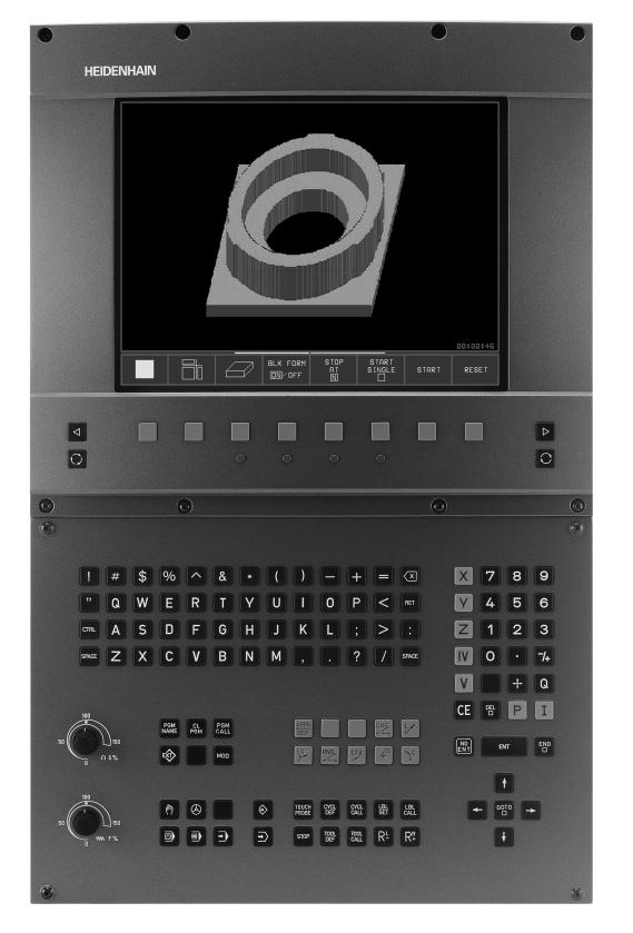
Controls
The TNC 406 and the TNC 416 are shop-floor programmable contouring controls for EDM machines with up to five axes.
Visual display unit and keyboard
The 14-inch color monitor (TNC 406) and 15-inch color monitor (TNC 416) display all information necessary for effective use of the TNC’s capabilities.
Program entry is supported by soft keys on the monitor.
The keys on the operating panel are grouped according to function. This makes it easier to create programs and use the TNC’s functions.
Programming
The user programs the TNC 406/TNC 416 right at the machine with interactive conversational-type guidance.
Graphics
Workpiece machining can be graphically simulated. Various display modes are available.
Compatibility
The TNC 406/TNC 416 can execute all programs whose commands belong to the command set of the TNC 406/TNC 416.
2 |
1 Introduction |

1.2Visual Display Unit and Keyboard
Visual display unit
The TNC 406 is delivered with the BC 110 color monitor (CRT); the TNC 416 can be delivered with the BC 120 color monitor (CRT) or the BF 120 flat-screen color monitor (TFT). The figure at top right shows the keys and controls on the BC 120, and the figure at bottom right shows those of the BF 120.
1Header
When the TNC is on, the selected operating modes are shown in the screen header.
2Soft keys
In the footer the TNC indicates additional functions in a soft-key row. You can select these functions by pressing the keys immediately below them. The lines immediately above the softkey row indicate the number of soft-key rows that can be called with the black arrow keys to the right and left. The line representing the active soft-key row is highlighted.
3Soft key selector keys
4Switching the soft-key rows
5Setting the screen layout
6Shift key for switchover between machining and programming modes
Keys on BC 120 only
7Screen demagnetization; Exit main menu for screen settings
8Select main menu for screen settings:
In the main menu: Move highlight downward
In the submenu: Reduce value or move picture to the left or downward
9In the main menu: Move highlight upward
In the submenu: Increase value or move picture to the right or upward
10In the main menu: Select submenu
In the submenu: Exit submenu
Main menu dialog |
Function |
BRIGHTNESS |
Adjust brightness |
|
|
CONTRAST |
Adjust contrast |
|
|
H-POSITION |
Adjust horizontal position |
|
|
V-POSITION |
Adjust vertical position |
|
|
V-SIZE |
Adjust picture height |
|
|
1
|
2 |
|
|
|
|
|
|
|
|
|
|
|
|
|
|
|
|
|
|
|
|
|
|
|
|
|
|
4 |
|
|
|
|
|
|
|
|
|
|
|
4 |
|
|
|
|
31 |
|
|
|
|
|
|
|
|
|
|
|
|
|
|
|
|
|
|
|
|
|
|
||
5 |
|
|
7 |
|
8 |
|
9 |
|
|
|
61 |
||
|
|
|
|
|
10 |
|
|||||||
|
|
|
|
|
|
|
|
|
|
|
|
|
|
|
|
|
|
|
|
|
|
|
|
|
|
|
|
1
|
|
|
2 |
|
|
|
|
|
|
|
|
|
|
|
|
|
|
|
|
|
|
51 |
|
41 |
|
|
3 |
4 |
|
6 |
||
|
|
|
|
1 |
|
|||||
|
|
|
|
|
|
|
|
|
|
|
|
|
|
|
|
|
|
|
|
|
|
1.2 Visual Display Unit and Keyboard
HEIDENHAIN TNC 406, TNC 416 |
3 |

1.2 Visual Display Unit and Keyboard
Main menu dialog |
Function |
SIDE-PIN |
Correct barrel-shaped distortion |
|
|
TRAPEZOID |
Correct trapezoidal distortion |
|
|
ROTATION |
Correct tilting |
|
|
COLOR TEMP |
Adjust color temperature |
|
|
R-GAIN |
Adjust strength of red color |
|
|
B-GAIN |
Adjust strength of blue color |
|
|
RECALL |
No function |
|
|
The BC 110 and BC 120 are sensitive to magnetic and electromagnetic noise, which can distort the position and geometry of the picture. Alternating fields can cause the picture to shift periodically or to become distorted.
Screen layout
You select the screen layout yourself: In the TEST RUN mode of operation, for example, you can have the TNC show program blocks in the left window while the right window displays programming graphics. You could also display the tool status in the right window instead, or display only program blocks in one large window. The available screen windows depend on the selected operating mode.
To change the screen layout:
Press the SPLIT SCREEN key: The soft-key row shows the available layout options (see ”Modes of Operation” on page 6).
Select the desired screen layout.
4 |
1 Introduction |
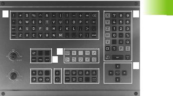
Keyboard
1
The figure at right shows the keys of the keyboard grouped according to their functions:
1Alphabetic keyboard for entering text and file names
2File management
MOD functions |
5 |
3 Programming modes |
21 |
4Machine operating modes
5Initiation of programming dialog
6 |
Arrow keys and GOTO jump command |
|
|
|
|
|
41 |
|
|
|
5 |
||
|
3 |
|
||||
7 |
Numerical input and axis selection |
|
|
|
|
|
|
|
|
|
|
||
|
|
|
|
|
The functions of the individual keys are described on the inside front cover. Machine panel buttons, e.g. NC START, are described in the manual for your machine tool.
7
6
1.2 Visual Display Unit and Keyboard
HEIDENHAIN TNC 406, TNC 416 |
5 |
1.3 Modes of Operation
1.3 Modes of Operation
Manual Operation, Incremental Jog, and Positioning with Manual Data Input
The Manual Operation mode is required for setting up the machine tool. In this mode of operation, you can position the machine axes manually or by increments, set the datums, and tilt the working plane.
The Incremental Jog mode of operation allows you to move the machine axes manually with the HR electronic handwheel.
Simple traverse movements can be programmed in the Positioning with Manual Data Input (MDI) mode of operation.
Soft keys for selecting the screen layout (see ”Screen layout” on page 4)
Screen windows |
Soft key |
Positions
Left: positions. Right: status display.
6 |
1 Introduction |
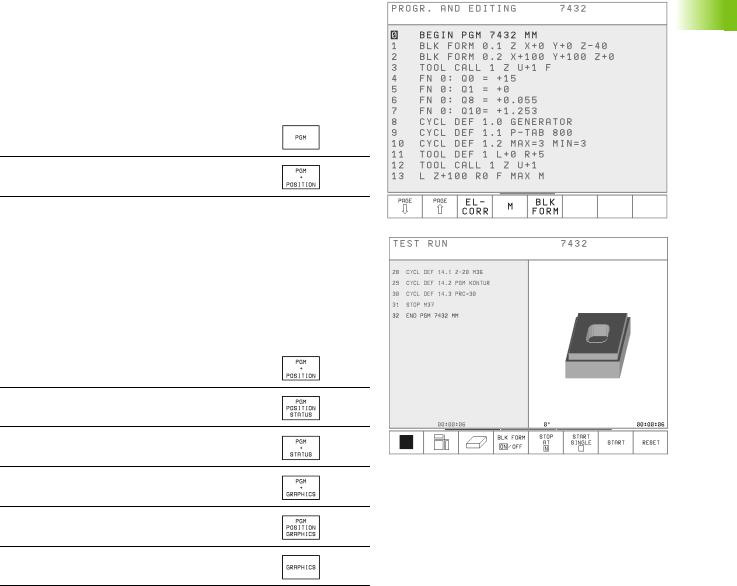
Programming and Editing
In this mode of operation you can write your part programs. The various cycles and Q parameter functions help you with programming and add necessary information.
Soft keys for selecting the screen layout
Screen windows |
Soft key |
Top: program. Bottom: positions
Top left: program. Top right: status
Bottom: positions
Test Run
In the Test Run mode of operation, the TNC checks programs and program sections for errors, such as geometrical incompatibilities, or missing or incorrect data within the program. This simulation is supported graphically in different display modes.
Soft keys for selecting the screen layout
Screen windows |
Soft key |
Top: program. Bottom: positions
Top left: program. Top right: status
Bottom: positions
Left: program. Right: status
Left: program. Right: graphics
Top left: program. Top right: graphics
Bottom: positions
Graphics
1.3 Modes of Operation
HEIDENHAIN TNC 406, TNC 416 |
7 |
1.3 Modes of Operation
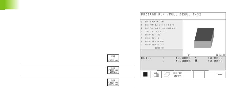
Program Run, Full Sequence and
Program Run, Single Block
In the Program Run, Full Sequence mode of operation the TNC executes a part program continuously to its end or to a manual or programmed stop. You can resume program run after an interruption.
In the Program Run, Single Block mode of operation you execute each block separately by pressing the machine START button.
Soft keys for selecting the screen layout
Screen windows |
Soft key |
Top: program. Bottom: positions
Top left: program. Top right: status
Bottom: positions
Top left: program. Top right: graphics
Bottom: positions
8 |
1 Introduction |

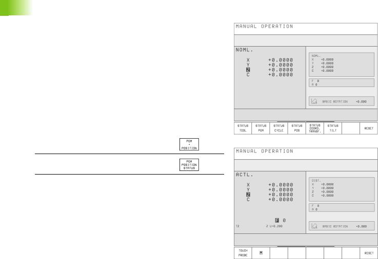
1.4 Status Display
General status display
Besides the coordinates, the status display also contains the following information:
Type of position display (ACTL, NOML, etc.)
Axis is locked (  on the axis)
Number of the current electrode T
Electrode axis
Feed rate F
Active miscellaneous functions M
TNC is in operation (indicated by  )
)
Name of the selected erosion table
Permissible power stages (GENERATOR cycle)
Current power stage
Additional status displays
In all modes of operation (except PROGRAMMING AND EDITING), you can split the screen layout to display additional status information in the right screen window:
Additional status display
Soft keys
Information on the current electrode
General program information
Information on the current OEM cycle
Positions and coordinates
Active coordinate transformations
Tilting the working plane
1.4 Status Display
HEIDENHAIN TNC 406, TNC 416 |
9 |
Loading...