


Operating Instructions
Diagnostic Set
03/2003
1. Contents |
|
|
1. Contents ...................................................................................................................................................... |
1 |
|
2. General Information....................................................................................................................................... |
5 |
|
2.1 |
Safety Instructions................................................................................................................................. |
5 |
2.2 |
Description of the PWM 8 Phase Angle Measuring Unit....................................................................... |
5 |
2.3 |
Functions of PWM 8 .............................................................................................................................. |
5 |
2.4 |
Power Supply ........................................................................................................................................ |
6 |
2.5 |
Items Supplied....................................................................................................................................... |
6 |
2.6 |
Software ................................................................................................................................................ |
7 |
2.7 |
Explanation of the Display..................................................................................................................... |
7 |
2.8 |
Setting the Display Contrast................................................................................................................ |
10 |
3. Operation..................................................................................................................................................... |
11 |
|
3.1 |
Display after Power-On ....................................................................................................................... |
11 |
3.2 |
Standard Soft-Key Row....................................................................................................................... |
11 |
4. Description of the PWM 8 MODE................................................................................................................ |
15 |
|
4.1 Switching the PWM 8 MODE .............................................................................................................. |
15 |
|
4.2 PWM 8 MODE: UNIVERSAL COUNTER with Frequency Display ..................................................... |
15 |
|
4.3 |
PWM 8 MODE: DETERMINE PULSE NUMBER with Frequency Display .......................................... |
16 |
4.4 PWM 8 MODE: MEASURE U/I ........................................................................................................... |
17 |
|
|
4.4.1 Display of the PWM 8 MODE: MEASURE U/I in the Mode Window........................................ |
18 |
4.5 PWM 8 MODE: MEASURE AMPLITUDES ......................................................................................... |
20 |
|
|
4.5.1 Measuring the Signal Amplitudes with 11µApp Interface Board: ............................................. |
21 |
|
4.5.2 Measuring the Signal Amplitudes with 1Vpp Interface Board .................................................. |
21 |
|
4.5.3 Measuring the Signal Amplitudes with TTL or HTL Interface Boards ...................................... |
22 |
5. EXPERT MODE .......................................................................................................................................... |
23 |
|
5.1 |
Activating the EXPERT MODE............................................................................................................ |
23 |
5.2 |
Auxiliary Functions in the EXPERT MODE ......................................................................................... |
23 |
|
5.2.1 The PRESET Editor ................................................................................................................. |
24 |
|
5.2.2 The Parameters ....................................................................................................................... |
25 |
|
5.2.3 Parameter Overview ................................................................................................................ |
25 |
6. Practical Application .................................................................................................................................... |
29 |
|
6.1 |
Power Supply of PWM 8 and Encoder................................................................................................ |
29 |
|
6.1.1 Power Supply of PWM 8 and Encoder via DC-IN Socket ........................................................ |
29 |
|
6.1.2 Power Supply of PWM 8 and Encoder via the Encoder Output (OUT) of the |
|
|
Interface Board......................................................................................................................... |
30 |
|
6.1.3 PWM 8 Power Supply via DC-IN Socket and Encoder Output (OUT) of the |
|
|
Interface Board......................................................................................................................... |
32 |
|
6.1.4 Voltage Monitoring Function of Encoder Supply...................................................................... |
33 |
|
6.1.5 Block Diagram: PWM 8 Power Supply Unit ............................................................................. |
35 |
7. Calibration ................................................................................................................................................... |
36 |
|
- 2 -
8. Specifications |
.............................................................................................................................................. |
37 |
||
8.1 |
Pin Layouts of the Interface Boards .................................................................................................... |
37 |
||
|
|
8.1.1 Pin Layout of the 11µApp Interface Board ............................................................................... |
37 |
|
|
|
8.1.2 Pin Layout of the 1Vpp Interface Board ................................................................................... |
37 |
|
|
|
8.1.3 Pin Layout of the TTL Interface Board ..................................................................................... |
38 |
|
|
|
8.1.4 Pin Layout of the HTL Interface Board..................................................................................... |
38 |
|
8.2 |
Pin Layout of the Power Supply Socket on PWM 8 ............................................................................ |
38 |
||
8.3 |
Specifications of PWM 8 Base Unit..................................................................................................... |
39 |
||
8.4 |
Specifications of 11µApp Interface Board ........................................................................................... |
40 |
||
8.5 |
Specifications of 1Vpp Interface Board ............................................................................................... |
40 |
||
8.6 |
Specifications of TTL Interface Board ................................................................................................. |
41 |
||
8.7 |
Specifications of HTL Interface Board................................................................................................. |
42 |
||
8.8 |
Specifications of Power Supply Unit ................................................................................................... |
42 |
||
9. Description of FST 2 Leak Tester................................................................................................................ |
43 |
|||
9.1 |
Explanation of the Controls and Displays ........................................................................................... |
43 |
||
9.2 |
Example for Application....................................................................................................................... |
44 |
||
9.3 |
Specifications of FST 2 ....................................................................................................................... |
45 |
||
10. Description of ROD 450 Rotary Encoder .................................................................................................. |
46 |
|||
10.1 |
Specifications of ROD 450 ................................................................................................................ |
46 |
||
11. Description of Connecting Cable 10-30V DC ............................................................................................ |
46 |
|||
12. Measuring Setup and Tolerances of the Output Signal............................................................................. |
47 |
|||
12.1 |
Description of the Output Signal ....................................................................................................... |
51 |
||
|
|
12.1.1 Output Signals........................................................................................................................ |
51 |
|
|
|
12.1.2 Output Signals........................................................................................................................ |
52 |
|
|
|
12.1.3 Output Signals........................................................................................................................ |
53 |
|
|
|
12.1.4 Output Signals........................................................................................................................ |
55 |
|
13. Adapter Connectors .................................................................................................................................. |
57 |
|||
13.1 |
Overview of the Adapter Connectors ................................................................................................ |
57 |
||
13.2 |
Adapter connector for exposed linear encode .................................................................................. |
58 |
||
13.3 |
Adapter-connector for ERN 1387...................................................................................................... |
59 |
||
14. Pin Layouts of Standard HEIDENHAIN Cables......................................................................................... |
60 |
|||
15. Description of the interface board, 1 Vpp, absolute (with Zn/Z1-track; EnDat/SSI; |
|
|||
SSI-programmable) ................................................................................................................................... |
64 |
|||
15.1 |
General information........................................................................................................................... |
64 |
||
|
|
15.1.1 |
1 Vpp measuring systems with Zn/Z1 track .......................................................................... |
64 |
|
|
15.1.2 |
1 Vpp measuring systems with EnDat interface.................................................................... |
65 |
|
|
15.1.3 |
1 Vpp measuring systems with SSI interface and 5V supply voltage ................................... |
65 |
|
|
15.1.4 |
1 Vpp measuring systems with SSI interface and HTL supply voltage................................. |
66 |
|
|
15.1.5 |
1 Vpp measuring systems with programmable SSI interface................................................ |
66 |
16 Items supplied ............................................................................................................................................ |
67 |
|||
16.1 |
Hardware........................................................................................................................................... |
67 |
||
16.2 |
Adapter Cables overview .................................................................................................................. |
67 |
||
16.3 |
Incremental Zn/Z1 ............................................................................................................................. |
68 |
||
16.4 |
Absolute EnDat/SSI .......................................................................................................................... |
69 |
||
16.5 |
Absolute EnDat/SSI motor encoder .................................................................................................. |
70 |
||
- 3 -
17 Software Description .................................................................................................................................. |
71 |
|||
17.1 |
Required software version................................................................................................................. |
71 |
||
17.2 |
Selecting the encoders via soft keys................................................................................................. |
71 |
||
|
17.2.1 Via the selection screen ......................................................................................................... |
71 |
||
|
17.2.2 Via parameter P9 in the EXPERT MODE .............................................................................. |
71 |
||
|
17.2.3 Switching the AB and CD tracks for 1Vpp encoders with Zn/Z1............................................ |
72 |
||
17.3 |
|
1 Vpp measuring systems with programmable SSI interface........................................................... |
73 |
|
|
17.3.1 Activating the menu for additional functions........................................................................... |
73 |
||
|
17.3.2 Switching the encoder supply to HTL..................................................................................... |
74 |
||
|
17.3.3 Parameter P10 "sensor connection" with programmable SSI encoders ................................ |
75 |
||
18 Specifications: Interface Board 1Vpp, absolute.......................................................................................... |
76 |
|||
18.1 |
Encoder input (IN) ............................................................................................................................. |
76 |
||
18.2 |
Encoder output (OUT)....................................................................................................................... |
76 |
||
18.3 |
Signal assignment of the BNC sockets ............................................................................................. |
76 |
||
18.4 |
Measuring encoder current/voltage................................................................................................... |
76 |
||
18.5 |
Measuring signal amplitudes............................................................................................................. |
76 |
||
18.6 |
Display of /UaS interference signal .................................................................................................. |
76 |
||
18.7 |
Terminating resistors......................................................................................................................... |
76 |
||
18.8 |
Pin layouts of drive encoders and absolute encoders....................................................................... |
77 |
||
|
18.8.1 |
1 Vpp measuring system with Zn/Z1 track ............................................................................ |
77 |
|
|
18.8.2 |
1 Vpp measuring system with EnDat interface ..................................................................... |
77 |
|
|
18.8.3 1 Vpp measuring system with programmed SSI interface .................................................... |
78 |
||
18.9 |
|
Adapter kit for non-HEIDENHAIN wiring .......................................................................................... |
79 |
|
|
18.9.1 Adapter kit 1 (Zn/Z1) for operation with Siemens and JH drives with |
|
||
|
|
|
HEIDENHAIN Zn/Z1 encoders and non-HEIDENHAIN wiring ................................................ |
79 |
|
18.9.2 Adapter kit 2 (EnDat/SSI) for operation with Siemens drives with HEIDENHAIN |
|
||
|
|
|
EnDat/SSI encoders and non-HEIDENHAIN wiring ............. |
80 |
18.10 |
Adapter cables for direct connection of PWM8 to the PCB connector of the encoder .................. |
81 |
||
|
18.10.1 Adapter cable with 12-pin PCB connector ........................................................................... |
81 |
||
|
18.10.2 Adapter cable with 14-pin PBC connector ........................................................................... |
82 |
||
18.11 |
Adapter cable 17/17-pin; PWM to motor (Pos.Enc.EnDat) ............................................................ |
83 |
||
18.12 |
Adapter cable to IK 115 interface card........................................................................................... |
84 |
||
18.13 |
Adapter cable 17/17-pin; PWM to motor (Mot.Enc.EnDat) ............................................................ |
85 |
||
18.14 |
Adapter cable 17/17-pin; PWM to motor (Mot.Enc.EnDat) ............................................................ |
86 |
||
18.15 |
Adapter cable 17/25-pin; PWM to subsequent electronics (Mot.Enc.1Vpp) .................................. |
87 |
||
18.16 |
Adapter cable 17/25-pin; PWM to subsequent electronics (Mot.Enc.EnDat)................................. |
88 |
||
18.17 |
Adapter cable 17/17-pin; PWM to motor (Mot.Enc.EnDat) ............................................................ |
89 |
||
- 4 -

2. General Information
2.1 Safety Instructions
Do not put defective units into operation!
1.2.
0 I
Fig 1: Connecting the PWM 8 in the position control loop of a machine tool controlled by TNC
In order to correctly judge the problems in a machine tool controlled by TNC, fundamental knowledge of the machine tool and its drives as well as their interaction with the measuring systems is required.
Inexpert handling may cause considerable damage and personal injury.
HEIDENHAIN is not liable for any damage or personal injury caused directly or indirectly or by improper use or incorrect operation.
Warning: Do not change any parameters or encoder voltages at the PWM while the machine tool is moving and a PWM is connected.
2.2 Description of the PWM 8 Phase Angle Measuring Unit
The PWM 8 phase angle measuring unit is a universal measuring unit for inspecting and adjusting HEIDENHAIN linear and rotary encoders.
The unit is operated by means of 5 soft keys. All values are displayed in a graphics display field. For each of the different encoder interfaces (11µApp, 1Vpp, TTL and HTL) a separate interface board is required. Each interface board is equipped with an encoder input (IN) and an encoder output (OUT). The unaltered scanning signals are available at the encoder output to be fed into e.g. a subsequent electronics. The PWM 8 may also be connected in series between the measuring system and the subsequent electronics. The axis functions of the machine tool are not impaired. It is also possible to use the PWM 8 separately for inspecting and adjusting measuring systems.
2.3 Functions of PWM 8
The main functions of PWM 8 are:
•Display of phase angle and on-to-off ratio
•Display of the scanning frequency
•Measurement of signal amplitude, current consumption and supply voltage of the encoder
•Display of the internal universal counter or the signal periods of a rotary encoder (pulse count)
•Display of reference signal, fault detection signal and counting direction
•Output of the amplified scanning signals (interface board: 11µApp, 1Vpp) or the original scanning signals (interface board: TTL, HTL) via 3 BNC sockets (e.g. to an oscilloscope)
-5 -

The following functions are available in the EXPERT MODE:
•Input of a preset for the internal universal counter
•Encoder voltage selectable
•Settings (e.g. dialogue language) programmable via parameters
2.4 Power Supply
Possibilities of powering PWM 8
•Line-powered via a separate 24V power supply unit (standard set)
•By an external, non-floating dc voltage source of 10 - 30 V / approx. 1 Ampere (adapter cable supplied with PWM 8).
•Via the subsequent electronics; encoder, PWM 8 and subsequent electronics must be connected in series (Caution: power consumption of PWM 8 approx. 5.5W).
The power supply of the measuring systems (external power supply unit or subsequent electronics) is selected via the soft keys of PWM 8.
If a voltage is connected to the DC-IN socket of PWM 8, the PWM base unit is always operated with this voltage.
If PWM 8 and/or the encoder are to be powered via the subsequent electronics,
•the encoder monitoring function of the subsequent electronics is active;
•it can be selected, how the encoder voltage of the subsequent electronics is fed to the encoder via PWM 8:
1.directly to the encoder (via parameter: P2 in EXPERT MODE)
2.via the switching regulator (integrated in PWM 8) with potential segregation and possibility of setting the encoder voltage.
2.5 Items Supplied
Diagnostic Set |
Items |
Id.No. |
|
Id.No. 312 431 01 |
Id.No. 312 431 02 |
|
|
+ |
+ |
PWM 8 |
309 956 .. |
+ |
Option |
FST 2 |
251 697 .. |
+ |
Option |
ROD 450 |
295 455 A1 |
+ |
+ |
Power supply unit |
313 797 .. |
+ |
+ |
Power cord 240V |
223 775 01 |
|
|
|
|
+ |
+ |
Adapter 10-30V DC |
317 293 01 |
+ |
+ |
BNC cable (3 pcs.) |
254 150 02 |
+ |
+ |
Connecting cable 9-pin |
309 773-01 |
+ |
+ |
Connecting cable 12-pin |
298 399-01 |
+ |
+ |
Operating instructions |
312 737 .. |
+ |
Option |
Interface board 11µApp |
323 083 .. |
Option |
Option |
Interface board 1Vpp |
323 077 .. |
Option |
Option |
Interface board TTL |
323 079 .. |
Option |
Option |
Interface board HTL |
322 732 .. |
Option |
Option |
Interface board Zn/Z1, EnDat, |
312 186 .. 1) |
|
|
SSI |
|
1) Description of the Interface board Id. Nr. 312 186 .. in section 15.
- 6 -
2.6 Software
For the PWM 8 phase angle measuring unit the following dialogues are available:
Dialogue |
|
Software - Id.No. |
|
|
English / German |
|
246 199-xx |
|
The last two places (xx) of the Id.No. represent |
English / French |
|
246 200-xx |
|
the software version. |
|
|
|
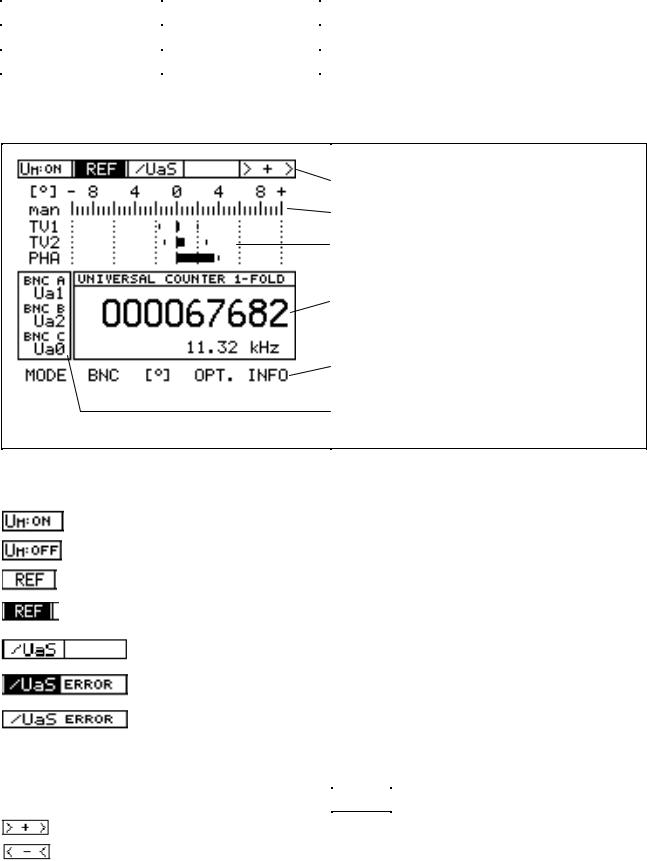
2.7 Explanation of the Display
Information on the encoder
Measuring range and scaling of the PHA/TV display
PHA/TV display with peak hold (here: maximum error: +TV2)
Display field for PWM 8 modes (here: UNIVERSAL
COUNTER and frequency display)
Soft-key row for operation
Current assignment of the BNC sockets
Structure of the display
The following information is permanently displayed: a): Information on the encoder:
Display: The supply voltage for the encoder is switched on.
Display: The supply voltage for the encoder is switched off.
Display: Reference signal
(no reference signal available)
The reference signal is displayed;
no real-time display of the reference signal!
Display: Fault detection signal
(no fault detection signal generated)
Fault detection signal generated, (active: low); at the same time the fault detection signal memory (ERROR) is set.
No fault detection signal generated; the fault detection signal memory (ERROR) has been set by an earlier fault.
The fault-detection memory can be deleted by:
1.activating another PWM 8 mode
2.switching the encoder voltage off and on
3.by pressing the soft key 

 of the INFO soft-key row.
Display of the counting direction: Encoder moves in forward direction
Display of the counting direction: Encoder moves in backward direction
- 7 -

b): Measuring range and scaling of the PHA/TV display:
Definitions:
TV1, TV2 : On-to-off ratio incremental signal 1, incremental signal 2.
At the zero crossover analogue incremental signals are triggered, i.e. converted into square-wave signals. One period (= on-time plus off-time of a square-wave signal) is subdivided into 360°.
If on-time and off-time of a square-wave signal are the same, i.e. 180° each (180° + 180° = 360°), the on-to-off ratio is 0°. If the on-time of a square-wave signal exceeds the off-time, the on-to-off ratio is positive. An on-to-off ratio of e.g. +10° means the on-time of the square-wave signal is 190° (180° + 10°) and the off-time 170° (180° - 10°).
PHA: Phase angle error between incremental signal 1 and incremental signal 2.
If the incremental signal 1 leads the incremental signal 2 by 90°, the phase angle error is 0°. The phase angle error is the deviation from the optimum phase shift of 90° dimensioned in degrees.
PHA/TV Display:
PHA and TV are displayed as bars. The scaling of the PHA/TV display can be set for different measuring ranges.
With automatic switch-over of the measuring range the (graduated) range of the PHA/TV display is automatically adapted to the biggest error (longest bar).
Measuring range of the PHA/TV display (here ± 25°)
With automatic switch-over of the measuring range the longest bar defines the measuring range.
Symbol for automatic switch-over of the measuring range.
Error display for: on-to-off ratio incremental signal 1 (TV1), on-to-off ratio incremental signal 2 (TV2), phase angle error between the two incremental signals (PHA)
If the measuring range is exceeded with manual switch-over of the measuring range, an
error is displayed. Switching over the measuring range: see standard soft-key row in section 3.2
Measuring range exceeded in negative direction
Measuring range exceeded in positive direction
Manual switch-over of the measuring range
- 8 -
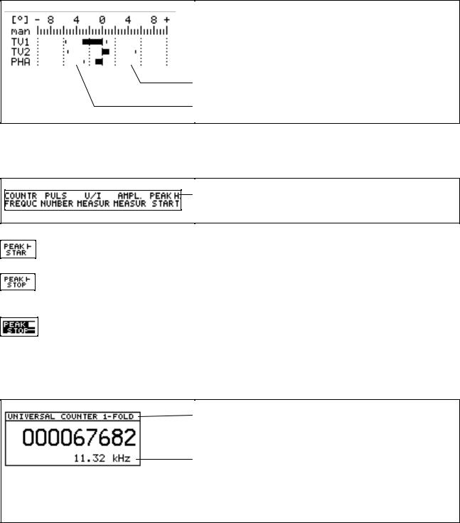
c): Peak hold of the PHA/TV display:
The peak hold holds and displays the maximum positive and negative value of the PHA/TV error.
It can be deleted by selecting a MODE or if the measuring range is exceeded. With automatic switch-over of the measuring range, peak hold is not active for PHA/TV display.
Display of positive peak hold
Display of negative peak hold
Manual start and stop of peak hold:
If the peak-hold display is to be valid only for a certain measuring range, it can be started and stopped by hand. Manual operation is made by means of the MODE soft-key row:
Soft key for manual control of the peak-hold display
Soft key for manual start of the peak-hold display in standard operation. The already existing peak-hold display is deleted.
After pressing the START soft key the STOP soft key is displayed. If this soft key is pressed, the peak-hold display is frozen and the bars of the PHA/TV display are hidden. Now the peak-hold display can be read.
After pressing STOP, this soft key is displayed inverted which signals "frozen status". By pressing the inverted soft key, the peak-hold display switches back to its initial status (standard operation).
d): Display field for PWM 8 MODE:
All MODES are displayed in the MODE window:
Headline MODE
(here additionally: edge evaluation of the
UNIVERSAL COUNTER))
Display field for the different MODES:
•UNIVERSAL COUNTER
•DETERMINE PULSE NUMBER
•MEASURE CURRENT/VOLTAGE
•MEASURE AMPLITUDES
See section 4, Description of the PWM 8 MODES
- 9 -
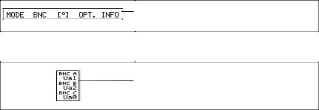
e): Soft-key row for operation of PWM 8:
The soft-key row makes PWM 8 easy to operate. It automatically configures itself according to the functions currently available.
Example: Soft-key row after power-on:
Standard setting of the soft-key row
f): Display field for the current assignment of the BNC sockets A, B and C:
This field contains the encoder signals currently fed to the three BNC sockets BNC A, B and C.
2.8 Setting the Display Contrast
The contrast of the LC display of PWM 8 (Id.No. 309 956 X2) can be set from outside. The trimmer for contrast adjustment is located next to the BNC socket C. A trimming screwdriver is required to change the contrast. The contrast of PWM 8 units with the Id.No. 309 956 X1 can only be set internally.
- 10 -
3. Operation
3.1 Display after Power-On
Software-Id.No. 246 199-xx;
the last two places symbolize the software version (here: version 01)
Automatic recognition of the interface board (here: TTL interface)
EXPERT MODE is active; see section 5
Software compensation data
(for calibration by HEIDENHAIN staff)
Note on software compensation data:
The software compensation display is intended for calibration by HEIDENHAIN staff. The settings displayed can only be changed by HEIDENHAIN, Traunreut.
3.2 Standard Soft-Key Row
After the power-on display, the standard soft-key row is displayed.
Possibilities of setting the standard soft-key row:
Switches to the soft-key row PWM 8 MODE (see PWM 8 MODE in section 4)
Assignment of the BNC sockets A, B and C to different encoder signals; after pressing the BNC soft-key, you can choose from the following options:
By pressing this soft key the BNC sockets A to C can be assigned to the encoder signals from memory 1 to 3.
Terminate assignment of BNC sockets
The default setting of the BNC memories made by HEIDENHAIN can be changed any time.
- 11 -
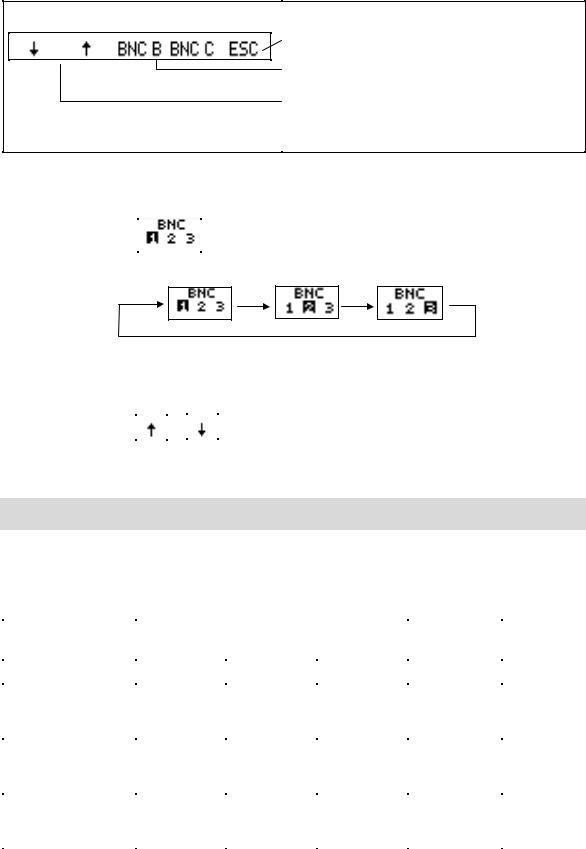
If e.g. the soft key BNC A is pressed, the assignment of the BNC socket A can be changed:
Terminate BNC assignment
Assignment of sockets B and C can be selected
Arrow keys to change the encoder signals of the selected BNC socket A
Switching the BNC memory:
The assignment of the BNC sockets is stored in three BNC memories that can be called successively.
Each time the soft key |
|
is pressed, the next BNC memory is activated. |
The display of the active BNC memory is highlighted:
Changing the signals in the BNC memories 1 to 3:
The signal in the active BNC memory is automatically stored each time it is changed by
pressing the soft keys |
|
or |
|
. |
After power interruption the signals of the BNC memory active last are allocated to the BNC sockets.
Notes on the use of the BNC sockets:
•When using the BNC sockets to measure the encoder signals with an oscilloscope, be sure that the workstation and the operator are properly grounded!
•A floating oscilloscope should be used to display the encoder signals with as little interference as possible. Always connect the oscilloscope to the socket of the switch cabinet of the machine tool to avoid signal distortions caused by different ground potentials.
The following encoder signals can be connected with the BNC sockets:
Interface Board |
Encoder signals on BNC socket |
BNC |
||
|
|
|
|
memory |
|
BNC A |
BNC B |
BNC C |
|
|
|
|
|
|
11µApp |
Ue1 |
Ue2 |
Ue0 |
1 |
|
U1+2 |
U1+2 |
NTR |
2 |
|
Ue0 |
Ue0 |
/UaS *) |
3 |
1Vpp |
A |
B |
R |
1 |
|
A+B |
A+B |
NTR |
2 |
|
R |
R |
/UaS *) |
3 |
TTL, HTL |
Ua1 |
Ua2 |
Ua0 |
1 |
|
/Ua1 |
/Ua2 |
/Ua0 |
2 |
|
Ua0 |
/Ua0 |
/UaS |
3 |
*) Signal is generated in the PWM 8.
- 12 -

Switching over the measuring range of the PHA/TV scaling.
The following measuring ranges can be selected:
The scaling currently selected is highlighted. When choosing automatic scaling (auto), the scaling is adapted to the biggest error (longest bar).
This soft key serves to activate the Options soft-key row.
The following functions are available:
Terminate Options
EXPERT-MODE; see section 5
The encoder can be powered INTERNALLY (by the power supply unit) or EXTERNALLY (by the subsequent electronics). Current setting: encoder powered INTERNALLY
The power supply for the encoder can be switched
ON and OFF.
The terminating resistors for the scanning signals (with TTL or HTL and 1 Vpp interface board only) can be switched ON and OFF. The current setting is stored in PWM 8 and reloaded after power interruption.
|
Interface board |
Terminating resistor [Ω] |
|||
|
|
|
|
|
|
|
|
0 V |
|
+U |
Switch- |
|
|
|
|
encoder |
able |
|
|
|
|
||
|
TTL |
91 |
|
215 |
yes |
|
HTL |
1200 |
|
1200 |
yes |
|
1Vpp |
|
121 |
yes 1) |
|
|
11µApp |
not available |
|
||
|
|
|
|
|
|
1) only possible with interface board Id.No. 323 077-XX or 312 246-01, index A
The active setting is highlighted in the Options soft-key row.
Note:
The soft key 

 is only displayed, if the PWM 8 is part of the encoder circuit, i.e. if a subsequent electronics (with encoder supply voltage) is connected to the encoder output of the interface board.
- 13 -

This soft key serves to display the Info soft-key row:
Terminate INFO
If more information is available, the PWM switches to the next INFO screen.
The interfering signal memory (ERROR) can be erased
The background lighting of the display can be switched on and off.
Information on PWM 8 and on the interface board can be displayed on the INFO screen.
Possible displays:
Encoder voltage of the subsequent electronics too low to ensure proper function; see section 6: Practical Application
11µApp, 1Vpp, TTL or HTL interface board
Terminating resistors for encoder signals: ON here: 200 Ω on + and 91 Ω on GND
The supply voltage for the encoder is provided
INTERNALLY (power supply unit).
Counting direction of the UNIVERSAL COUNTER (here: backward counting when encoder moves in forward direction).
The power supply of the encoder can be set to 10V max. without limit (except HTL); see section 3.2.2 Parameter Programming
The UNIVERSAL COUNTER starts with the next reference pulse.
With the interface board 11µApp the amplification of the output signals is indicated. The output signal of e.g. 11µApp is displayed as a 3.3 Vpp voltage signal at the oscilloscope.
The EXPERT MODE has been activated (see section 3)
The PRESET entered for the UNIVERSAL
COUNTER is displayed.
- 14 -

4. Description of the PWM 8 MODE
4.1 Switching the PWM 8 MODE
After the power-on message, the standard soft-key row is displayed, from which the MODE soft-key row of PWM 8 can be called:
Soft key to call PWM 8 MODE
The following PWM 8 modes can be selected from the MODE soft-key row:
Start/stop of peak hold
Measure signal amplitudes
Measure the current consumption of the encoder and the encoder voltage (and the sensor voltage)
Determine the pulse count of the encoder (e.g. rotary encoder) and frequency display
UNIVERSAL COUNTER with frequency display
For each PWM 8 MODE the following auxiliary displays are active: (Description see section 2.7: Explanation of the display)
•Display of the reference signal
•Encoder monitor with memory function
•Display of the counting direction
•PHA/TV display
•Assignment of the BNC sockets
After power interruption the last active mode is loaded again.
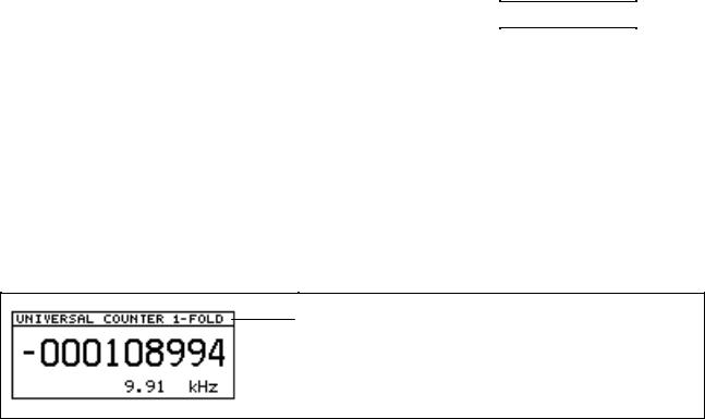
4.2 PWM 8 MODE: UNIVERSAL COUNTER with Frequency Display
The UNIVERSAL COUNTER counts the triggered edges of the incremental signals 1 and 2 of the encoder.
Note:
The function of the UNIVERSAL COUNTER is defined by the counter parameters P5 to P7. The UNIVERSAL COUNTER can be loaded with a preset. See section 5: EXPERT MODE, parameters and PRESET editor.
MODE UNIVERSAL COUNTER with edge evaluation (see parameter P4)
Display of universal counter
Frequency display
Sign
- 15 -

Clearing the UNIVERSAL COUNTER:
The UNIVERSAL COUNTER is cleared by pressing the soft key 
 a second time.
Frequency counter:
The frequency counter operates up to a frequency of 2 MHz.
The frequency is derived from the incremental signal 1.
4.3 PWM 8 MODE: DETERMINE PULSE NUMBER with Frequency Display
The MODE DETERMINE PULSE NUMBER is intended to find the pulse count of a rotary encoder. The parameter P5: EDGE EVALUATION is automatically set to 1-fold, the parameter
P6: COUNTING MODE to 0-1-2!
MODE DETERMINE PULSE NUMBER
Pulse number (line count)
Frequency display
Proceeding to determine the pulse count:
First reference signal starts the pulse counter
Break of approx. 1 second (= display time of the pulse count)
Display of intermediate pulse counts
Next reference signal stops the pulse counter
Display of the pulse count
Each time "DETERMINE PULSE NUMBER" is activated, the pulse counter is reset, i.e. the
next reference signal starts the counter, the next but one stops it. This function can be of use e.g. when operating with measuring systems with distance-coded reference marks.
- 16 -
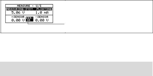
4.4 PWM 8 MODE: MEASURE U/I
The PWM MODE: MEASURE U/I the current consumption and the power supply of the encoder can be measured.
Depending on the interface board also the sensor voltages can be measured as well.
In the subsequent electronics the sensor lines serve to tap the encoder voltage directly at the encoder at high resistance and to feed it back to the subsequent electronics. Voltage drops on the supply lines of the encoders are then compensated in subsequent electronics offering compensation.
TTL, HTL and 1Vpp encoders are equipped with sensor lines.
If an error is detected during measurement of the sensor voltages, a blinking error field is displayed in MODE: MEASURE U/I.
Error display during measurement of the sensor voltage
A sensor-voltage error is displayed, if:
+ sensor smaller than 90 % of U-MSYS, or - sensor larger than 10 % of U-MSYS
Note:
In the PWM 8 MODE: MEASURE U/I the supply lines of the encoder and the sensor lines are separated, whereas in all other PWM 8 MODES they are connected to each other!
The current consumption of the terminating resistors (with TTL and HTL interface boards) is displayed together with the current consumption of the encoder. I.e. even if no encoder is connected, the current consumption of the encoder is displayed, if the terminating resistors and the encoder supply voltage are switched on.
- 17 -

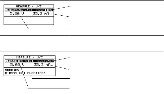
4.4.1 Display of the PWM 8 MODE: MEASURE U/I in the Mode Window
Depending on the power supply of the encoder and of PWM 8, the MODE MEASURE U/I may be displayed differently in the MODE window:
MODE: MEASURE U/I of encoders with sensor lines
(TTL, HTL, 1Vpp interface boards):
•and internally powered encoder (= via power supply unit) or
•externally powered encoder and parameter: P2 U-MSYS EXTERN = FLOATING
Floating power supply of the encoder with relation to the subsequent electronics.
Current consumption of the encoder
Power supply of the encoder (here: floating)
Sensor lines of the encoder
Special feature of HTL interface board:
A floating power supply of the encoder is not possible. The parameter P2 has no function. The MODE MEASURE U/I is displayed as follows with HTL interface board:
Special feature of HTL interface board: The encoder is powered by the power
supply unit (= internally) without potential segregation.
• externally powered encoder and parameter: P2 U-MSYS EXTERN = FROM CUSTOMER
The encoder is powered directly by the subsequent electronics without potential segregation.
Current consumption of the encoder
Power supply of the encoder (here: customer voltage)
Sensor voltages of the encoder
- 18 -
MODE: MEASURE U/I of encoders without sensor lines
(11µApp interface boards):
•und interner Meßsystemversorgung (= aus Externem Netzteil) oder
•externer Meßsystemversorgung und Parameter: P2 U-MSYS EXTERN = POTENTIALFREI
Floating power supply of the encoder with relation to the subsequent electronics.
Current consumption of the encoder
Power supply of the encoder
• externer Meßsystemversorgung und Parameter: P2 U-MSYS EXTERN = VON KUNDE
The encoder is powered directly by the subsequent electronics (customer) without potential segregation
Current consumption of the encoder
Note: No potential segregation between encoder and subsequent electronics
Power supply of the encoder (= customer voltage)
- 19 -

4.5 PWM 8 MODE: MEASURE AMPLITUDES
In this mode the vertices of the amplitudes of the incremental signals 1 and 2 are measured. The result always refers to an individual signal period. With sinusoidal encoder signals (11µApp and 1Vpp) the positive and the negative vertices are measured versus U0, with square-wave encoder signals (TTL and HTL) low and high level are measured versus 0V.
In the table below the maximum measuring ranges are listed for the different interface boards:
Interface board: |
11µApp |
1Vpp |
TTL |
HTL |
Maximum measuring range |
33 µApp |
1.66 Vpp |
low: 0 – 2.5 V |
low: 0 – 7.5 V |
|
|
|
high: 2.5 – 7.5 V |
high: 7.5 – 22.5 V |
If the EXPERT MODE is active (see section 5) and the 11 µApp or 1Vpp interface board used, the encoder supply voltage can be set in the mode MEASURE AMPLITUDES:
For this purpose the standard soft-key row has been expanded by the soft key 
 .
.
Soft key to switch to setting of encoder voltage
After pressing the soft key 
 the encoder voltage can be set:
Soft key to switch back to the standard soft-key row
Display of encoder voltage
Soft keys to set the encoder voltage
- 20 -
4.5.1 Measuring the Signal Amplitudes with 11µApp Interface Board:
Definitions:
SYM.1: Symmetry 1, ratio of positive to negative
half wave of incremental signal Ie1 (versus U0)
SYM.2: Symmetry 2, ratio of positive to negative
half wave of incremental signal Ie2 (versus U0)
I |
|
|
0 |
a |
c |
|
||
|
b |
t |
|
|
Calculation: |
a |
- b |
Result: ideal = 0 |
|
2 ´ c |
||||
|
|
|||
I1 / I2: Amplitude ratio, amplitudes of incremental signals Ie1 versus Ie2
Calculation: |
CIe1 |
||
|
|
Result: ideal = 1 |
|
|
|||
|
CIe2 |
||
|
|
|
|
Result is displayed in µApp
Datum for measurement of sign. amplitude (U0)
Bar display of incremental signal 1.
The position of the bars stands for the symmetry of the incremental signals.
Bar display of incremental signal 2.
Range for measurement of the signal amplitude; here: 33 µApp (± 16.5µApp)
Numerical peak-to-peak value of the signal amplitudes of the incremental signals 1 and 2 in µApp.
4.5.2 Measuring the Signal Amplitudes with 1Vpp Interface Board
Definitions:
SYM.A: Symmetry A, ratio of positive to negative
half wave of incremental signal A, (versus U0).
SYM.B: Symmetry B, ratio of positive to negative
half wave of incremental signal B, (versus U0).
U |
|
|
0 |
a |
c |
|
||
|
b |
t |
|
|
Calculation: |
a |
- b |
Result: ideal = 0 |
|
2 ´ c |
||||
|
|
|||
A / B: Amplitude ratio, amplitudes of incremental signals Ie1 versus Ie2
|
C A |
|
Calculation: |
|
Result: ideal = 1 |
|
||
|
C B |
|
- 21 -
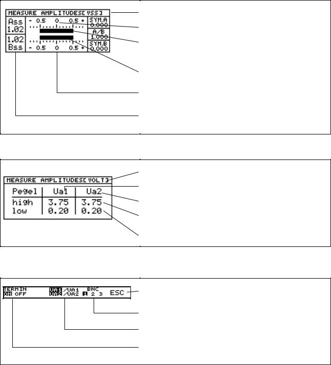
Result is displayed in Vpp.
Datum for measurement of sign. amplitude (U0)
Bar display of incremental signal A.
The position of the bars stands for the symmetry of the incremental signals.
Bar display of incremental signal B.
Range for measurement of the signal amplitude; here: 1.66 Vpp
Numerical peak-to-peak value of the signal amplitudes of the incremental signals A and B in Vpp.
4.5.3 Measuring the Signal Amplitudes with TTL or HTL Interface Boards
Result is displayed in V
Incremental signal 1
Incremental signal 2
High level of a signal amplitude in V
Low level of a signal amplitude in V
The following options are available in the corresponding soft-key row:
Terminate measurement of signal amplitudes
Switch the BNC memory for BNC sockets A to C
Switch to inverted signals
Switch terminating resistors on and off (defined load of the square-wave signals). The highlighted option is active.
Special feature of HTL interface board:
Up to software version 05:
With HTL encoders the inverted signals may not be available depending on the encoder.
Check whether the inverted signals are available before measuring the signal amplitudes. PWM 8 cannot recognize, whether there are inverted signals or not!
If the inverted signals are missing, incorrect values are displayed for the signal amplitudes!
From software version 05:
If the encoder does not provide inverted signals, "------" is displayed for the signal levels of the inverted signals.
- 22 -
5. EXPERT MODE
In addition to the standard functions PWM 8 offers further possibilities in the EXPERT MODE:
•Input of a PRESET
•Possibility of adjusting the encoder voltage
•Parameter programming
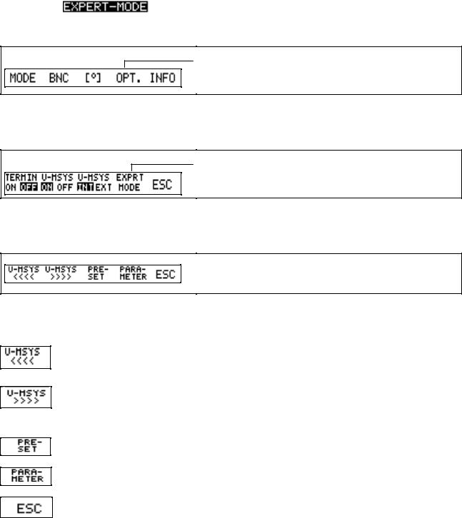
5.1 Activating the EXPERT MODE
The EXPERT MODE is activated by pressing the left and the right soft key while the power-on screen is displayed.
The message: is displayed.
With parameter P4: SAVE EXPERT MODE the activation of the EXPERT MODE can be automated. After the power-on screen the standard soft-key row is displayed:
Press soft key: OPT.
After pressing the soft key OPT. (OPTIONS) in this soft-key row, the OPTIONS soft-key row is displayed. From there you can switch to the EXPERT MODE.
Press soft key: EXPERT MODE
When pressing the soft key EXPERT MODE, the following options are displayed. Soft-key row of the EXPERT MODE:
5.2 Auxiliary Functions in the EXPERT MODE
Reduce U-MSYS:
The power supply of the encoder can be reduced to approx. 3V (HTL interface board: 10V).
Increase U-MSYS:
The power supply of the encoder can be increased to approx. 6V (HTL interface board 19V when operating with an external 24V power supply unit).
See parameter P3: U-MSYS Limit
Activating the PRESET editors:
In the PWM 8 MODE: UNIVERSAL COUNTER a PRESET can be entered.
Activating PARAMETER programming
The PWM 8 can be configured by means of parameters.
To terminate the EXPERT MODE press the soft key ESC.
- 23 -
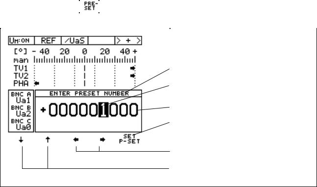
5.2.1 The PRESET Editor
The UNIVERSAL COUNTER (PWM 8 MODE: UNIVERSAL COUNTER) can be loaded with a PRESET. In this case the UNIVERSAL COUNTER starts counting from this value.
After pressing the soft key: |
|
in the soft-key row of the EXPERT MODE the PRESET editor is |
|
activated. |
|
|
|
|
|
|
|
PRESET editor
The highlighted figure can be edited.
Display field for the PRESET
By pressing the soft key SET P-SET the displayed PRESET is transferred into the UNIVERSAL COUNTER.
These soft keys serve to move the highlight to the figure (or to the sign) to be changed.
With these soft keys the highlighted figure (or the sign) can be edited.
- 24 -
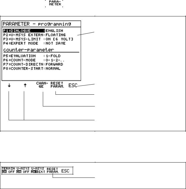
5.2.2 The Parameters
By means of parameter programming several PWM 8 settings can be changed.
After pressing the soft key |
|
in the soft-key row of the EXPERT MODE, the menu for parameter |
programming is displayed. When commissioning PWM 8 the parameter default setting is as follows:
Current parameter setting
Terminate parameter programming
All parameters are reset to their default values (fig.: parameter default setting)
The highlighted parameter can be changed by pressing the soft key CHANGE
By pressing these soft keys the highlighted field can be moved to the parameter to be edited.
If parameters are changed, PWM 8 internally stores the changes. When the PWM 8 is switched on again, the stored parameter values are loaded.
If parameter values have been stored that are different from the standard setting and the EXPERT MODE is not active, the standard setting can be loaded from the Options soft-key row.
However, the parameter P1 Dialogue is not changed.
With this soft key the parameter default setting can be loaded in the Options soft-key row.
5.2.3 Parameter Overview
Parameter P1: Dialogue Language
[GERMAN, ENGLISH] |
Software Id.No.: 246 199 xx |
[GERMAN, FRENCH,] |
Software Id.No.: 246 200 xx |
The dialogue of PWM 8 can be switched. Possible language combinations are German/English and German/French.
- 25 -
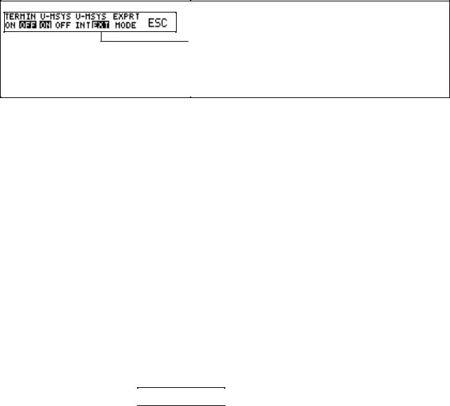
Parameter P2: U-MSYS EXTERN [FLOATING, FROM CUSTOMER]
Note: Parameter P2 is only effective, if the encoder is powered externally (= by a subsequent electronics, e.g. a counter, a control or customer electronics). In this case PWM 8 can be switched to EXTernal power supply of the encoder in the Options soft-key row:
Soft key to switch to EXTernal power supply of the enocder. This soft key is only displayed, if an encoder voltage of a subsequent electronics has been connected to the encoder output of the interface board.
Shown setting: encoder is powered externally.
If the encoder is powered EXTERNALLY, parameter 2 serves to choose whether the encoder supply of the subsequent electronics is to be
•floating with relation to PWM 8 (potential segregation) (parameter setting: FLOATING), or
•directly fed to the encoder without being changed by PWM 8 (parameter setting: FROM CUSTOMER).
Special feature of HTL interface board:
When using a HTL interface board, parameter P2 is not available. The measuring system
can only be powered with the potential of the subsequent electronics. Potential segregation is not possible!
Why is potential segregation required between PWM 8 and subsequent electronics?
Owing to different reference potentials of the encoder signals 11µApp/1Vpp (U0) and the interface boards (0V) the signals may be shifted, which can cause counting errors in the subsequent electronics and in the most unfavorable case result in a measuring circuit error. Potential segregation avoids signal shifts and ensures that the encoder circuit operates correctly, when PWM 8 is switched on.
Notes on floating encoder supply from the subsequent electronics:
(Parameter P2: FLOATING)
1.To ensure trouble-free functioning of subsequent electronics with 11µApp and 1Vpp encoder inputs.
2.In the PWM 8 the power supply of the encoder is generated by a switching regulator, providing 5.0V (standard setting) irrespective of the encoder power supply of the subsequent electronics. If required, the encoder voltage can be set manually.
For this purpose the soft keys 
 in the soft-key row of the EXPERT MODE are available.
Note on HTL interface boards:
When using a HTL interface board the standard setting of the encoder voltage is 12V, if there is no supply voltage of the subsequent electronics at the OUT flange socket of the interface board. If there is a voltage, PWM 8 "connects" the HTL encoder voltage to the encoder voltage of the subsequent electronics. With HTL interface boards potential segregation is not possible.
3.The current intensity of the encoder voltage is set to 500 mA; if the terminating resistors (with TTL and HTL interface boards) are switched on, it is 700 mA.
4.Owing to potential segregation the power consumption of the encoder supply by the subsequent electronics is approx. 50% higher than it would be without potential segregation (due to the efficiency of the DC/DC converter and the switching regulator). Please also note the increased voltage drop on the encoder supply line caused by the higher current intensity!
-26 -
Notes on encoder supply directly from the subsequent electronics:
(Parameter P2: FROM CUSTOMER)
1.Trouble-free functioning of subsequent electronics with 11µApp and 1Vpp encoder interfaces cannot be guaranteed due to signal shifts of the subsequent electronics!
2.The encoder voltage of the subsequent electronics is fed directly to the encoder without being changed by PWM 8; it cannot be altered.
3.There is no current limitation for the encoder voltage.
4.The power consumption of the subsequent electronics for the encoder supply is only slightly higher than that of the encoder. About 10 mA are required for the voltage monitor of the subsequent electronics.
Parameter P3: U-MSYS LIMIT [ON (6 VOLTS), OFF (9 VOLTS)]
Parameter P3 defines the maximum limits for the encoder voltage. By switching off the U-MSYS limit the encoder voltage can be set in the range of 9V ±1V.
Caution: The measured object may be destroyed by overvoltage! Standard encoders are operated with a voltage of 5V ± 5%.
Special feature of HTL interface boards:
When using the HTL interface board, parameter P3 is not available!
In the EXPERT MODE the encoder voltage can only be set with the soft keys 
 if the parameter P2 is set to FLOATING.
Parameter P4: EXPERT MODE [NOT SAVE, SAVE]
If parameter P4 is set to SAVE, the EXPERT MODE is reactivated after power interruption;
if it is set to NOT SAVE, the EXPERT MODE must be reactivated each time power is switched on.
Parameter P5: EVALUATION [1-FOLD, 2-FOLD, 4-FOLD]
In parameter P5 the edge evaluation of the UNIVERSAL COUNTER (PWM 8 MODE UNIVERSAL COUNTER) is set. It defines how many edges per signal period of incremental signal 1 and incremental signal 2 are transferred to the UNIVERSAL COUNTER and used for measurement of the frequency.
In the PWM 8 MODE: DETERMINE PULSE NUMBER the evaluation is automatically set to 1-FOLD. The EVALUATION is displayed next to the headline of the UNIVERSAL COUNTER:
Display of edge evaluation of the universal counter (here: 1-FOLD)
Parameter P6: COUNTING MODE [0-1-2, 0-2-4, 0-5-0]
Parameter P6 defines the COUNTING MODE of the last digit of the UNIVERSAL COUNTER.
- 27 -
 Loading...