


Operating Instructions
IK 5000 QUADRA-CHEK
(QC 5000)
Video Edge Detection Systems
English (en) 2/2010
QC5200 Series
User’s Guide
Video Edge Detection Systems
QC5200, QC5210, QC5230 and QC5240
QC5200 Series User’s Guide
Video edge detection systems: QC5200, QC5210, QC5230, and QC5240
Printed in the United States of America
All information set forth in this document, all rights to such information, any and all inventions disclosed herein and any patents that might be granted by employing the materials, methods, techniques or apparatus described herein are the exclusive property of Metronics Inc., Bedford, New Hampshire
Terms, conditions and features referenced in this document are subject to change without notice
No part of this document may be reproduced, stored in a retrieval system, or transmitted in any form or by any means, electronic, mechanical, photocopying, recording, or otherwise, without prior written permission of Metronics, Inc.. Requests to Metronics, Inc. for permission should be addressed to the Technical Services Department, Metronics, Inc., 30 Harvey Road, Bedford, New Hampshire 03110. The Technical Services Department can be reached by phone at (603)-622.0212
Limit of liability and disclaimer of warranty
While Metronics, Inc. exercised great care in the preparation of this book, Metronics makes no representations or warranties with respect to the accuracy or completeness of the contents of this book and specifically disclaims any implied warranties of merchantability or fitness for a particular purpose. The advice, methods and instructions contained in this book might not be suitable for your situation. When in doubt regarding suitability, you are encouraged to consult with a professional where appropriate. Metronics shall not be liable for any loss of profit or any damages, including but not limited to special, incidental, consequential or other damages
Trademarks
Metronics is a registered trademark of Metronics, Inc. and its subsidiaries in the United States and other countries and may not be used without written permission. Other trademarks are the property of their respective owners
Metronics part number: |
11A10558 |
Publishing date: |
June, 2005 |

Introduction
This User Guide describes the operation of the video edge series of QC5200 metrology products. This series of QC5200 instruments conducts a wide variety of precise 2-D measurements using a wide assortment of video edge detection probes. The QC5200 software supports manual part positioning and feature measurement under user control, and CNC part positioning and automated measurement under program control. While it is likely that this Guide includes some material that doesn’t apply to your specific QC5200 system, information pertaining to your system will be easy to find using the Table of Contents and Index
Who should read this Guide?
This Guide is necessary for the efficient operation of the QC5200 system. Operators and supervisors will find the contents invaluable in conducting measurements, programming automatic functions and reporting results. User setup functions are also described that will help users and supervisors customize the QC5200 measurement tools, user interface screens and report formats
Prerequisites
Operators and supervisors are assumed to have a good basic understanding of dimensional metrology theory and practice, and a good understanding of Microsoft Windows use and conventions
Conventions used throughout this Guide
The conventions used to call attention to notes, cautions and warnings, and the shorthand used to show menu navigation paths are described below
Notes, warnings and cautions
This guide uses the following icons to highlight note, warning and caution information
NOTE
The note icon indicates additional or supplementary information about an activity or concept. Notes are shown in bold type.

ii
QC5200 Series User’s Guide
CAUTION
The exclamation point icon indicates a situation or condition that can lead to equipment malfunction or damage. Do not proceed until the caution message is read and thoroughly understood. Caution messages are shown in bold type.
WARNING
The raised hand icon warns of a situation or condition that can lead to serious equipment damage, personal injury or death. Do not proceed until the warning is read and thoroughly understood. Warning messages are shown in bold type.
Menu path navigation
Throughout the Guide, many references are made to screens that must be displayed by clicking the mouse cursor on a series of menu items and screen tabs. This kind of navigation path is demonstrated in this example of displaying the Tools/Customize/Colors screen, shown in text as: Tools/Customize/Colors
Clicking the Tools menu item... |
then clicking the Customize menu item... |
then clicking the Colors tab... displays the Tools/Customize/Colors screen
Introduction
On-screen menu commands
iii
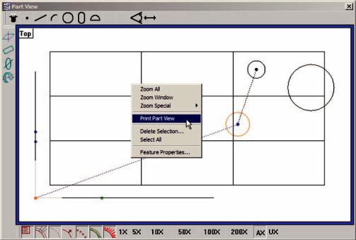
Many commands are displayed by right-clicking the mouse cursor in a window, and then on one or a series of menu items. This kind of command path is demonstrated in this example of using the Part View window/Print Part View command to print the part view. The command is shown in text as: Part View window/Print Part View
Right-clicking the Part View window, then clicking Print Part View prints the current part view
iv
QC5200 Series User’s Guide
Guide organization
This Guide contains eleven chapters and three reference appendices. An overview of the contents is provided below. Experienced users are encouraged to familiarize themselves with the first six chapters before beginning to use the QC5200. Users that are new to the QC5200 and similar Metronics products should read the first six chapters carefully and then follow the tutorial in Chapter 3: Quick Start Demonstartion before beginning
Table of contents
Chapter 1: System overview
Brief introduction to the QC5200 series features and benefits
Chapter 2: User interfac
Comprehensive description of the user interface covering screens, menus, toolbars the statusbar and work-
Chapter 3: Quick Start Demonstration
Brief demonstration of using the basic functions of the QC5200 including
•Organizing the workspace
•Selecting and teaching the probe
•Recording measurement activities as a program
•Measuring & constructing datums
•Measuring features
•Applying tolerances
•Exporting data
•Reporting
•Saving the part and program
Chapter 4: Probes
Instructions for calibrating and using video edge detection measurement probes
Chapter 5: Measuring
Instructions for constructing datums and measuring, constructing and creating features.
Chapter 6: Tolerancing
Instructions for applying tolerances to measurements
Chapter 7: Reporting and templates
Instructions for organizing, formatting, exporting and printing measurement results
Chapter 8: Programming
Descriptions of programming functions and instructions for creating, editing, and debugging programs

Introduction
Chapter 9: Encoder Setup
v
Instructions for calibrating and configuring axis encoders
Chapter 10: Supervisor Setup
Descriptions of setup tools and screens used to configure and customize measurement, programming and display parameters
Chapter 11: Problem solving
Basic troubleshooting guide in the form of a simple table of symptoms, probable causes and recommended
solutions
Appendix A: File Formats
Appendix B: ASCII Codes
Appendi x C: Tolerances
Index

vi |
QC5200 Series User’s Guide |
Safety first!
The QC5200 is inherently safe, and in proper use few if any potential safety hazards exist. However, many systems include motorized CNC stages that, as is the case with all motorized equipment, must be treated with caution to avoid collision and pinch injuries. Also, an entire system often consists of electrical equipment connected by many cables, which must be treated with care to avoid shock and tripping injuries
 ARNINGS - AXIS MOTION
  lways stay clear of axis motion paths.
 isconnect axis motor power when motor activities are not required.
Be prepared to depress the emergency off mushroom switch or other similar device quickly in the event of an emergency when motor axes are active.
 ARNINGS - ELECTRICAL
 isconnect the system components from electrical sources before cleaning or
 ervicing.
 o not allow any power cord or signal cable to be located such that it can be walked on or create a tripping hazard.
The system components are equipped with 3-wire power plugs that include a separate ground connection, or are grounded through a separate wire. Always connect the power plug to a 3-wire grounded outlet. The use of 2-wire power plug adapters or any other connection accessories that remove the third grounded connection create a safety hazard and should not be permitted. If a 3-wire grounded outlet is not available, ask your electrician to provide one. Never disconnect any separate ground wire.
Do not open the QC5200 enclosure. There are no user-serviceable components or assemblies inside.
General safety precautions
General safety precautions must be followed when configuring, maintaining or operating the system. Failure to observe these precautions could result in damage to the equipment, or injury to personnel.
It is understood that safety rules within individual companies vary. If a conflict exists between the material contained in this guide and the rules of a company using this system, the more stringent rules should take precedence
Additional safety information is included throughout the remainder of this guide
Introduction |
vii |
General Maintenance
Disconnect the QC5200 from the power source and seek the assistance of a qualified service technician if
•The power cord is frayed or damaged or the power plug is damaged
•Liquid is spilled or splashed onto the enclosure
•The QC5200 has been dropped or the exterior enclosure has been damaged
•The QC5200 exhibits degraded performance or indicates a need for service some other way
Cleaning
Use only a cloth dampened with water and a mild detergent for cleaning the exterior surfaces and display screens. Never use abrasive cleaners, and never use strong detergents or solvents. Only dampen the cloth, do not use a cleaning cloth that is dripping wet
Display Resolution and Units of Measure
Display resolutions in this guide are examples. User display resolutions are likely to vary according to the specific application. Metric units of measure are used in examples
Accuracy & Precision
Measurement accuracy is determined by many factors, such as the resolution of the encoders connected to axis inputs. Generally, the display resolution of the QC5200 can exceed encoder resolutions. Setting the display resolution to exceed the encoder resolution does not increase measurement accuracy
Getting Help
Help is available in this printed Guide, in the electronic version of this Guide accessed from the Help menu of the QC5200 software, from your Metronics distributor or system provider and directly from Metronics.
The information contained in this guide should be adequate to customize the measurement, display and programming aspects of system, and to perform the minimal setup and troubleshooting required beyond the services provided by your Metronics distributor or system provider. However, in the event that your Metronics distributor or system provider cannot provide the assistance you need, our support staff is committed to insuring your positive experience with the QC5200 series of products. To receive technical support
Routine issues
e-mailour support staff at: techsupport@metronics.com

viii
QC5200 Series User’s Guide
Urgent issues
Telephone your Metronics distributor, or telephone our support staff at: (603) 622.0212
 OTE
OTE
 it becomes necessary to contact us directly, be prepared to supply the following
 formation
 The QC5200 series serial number
 (5-Digit number printed on back label)
 • A description of the equipment attached to the QC5200 computer, including the manufacturer and model number
• The QC5200 software version number, found on the Help/About QC5000
Updating your QC5200 software
The most recent version of the QC5200 software can be downloaded from the Product Support section of our web site at
http://www.metronics.com
Please carefully read all the instructions and cautions published on our site regarding your software update before attempting to perform the update
Additional publications for the QC5200
Additional application or instructional information is sometimes available for download from the Product Support section of our web site at
http://www.metronics.com

Contents 1
Contents
Chapter |
System Overview |
|
|
Overview of system features |
|
Chapter 2 |
User Interface |
|
|
Introduction |
7 |
|
Windows |
8 |
|
DRO |
8 |
|
Templates |
8 |
|
Results |
8 |
|
Part View |
8 |
|
Live Video |
8 |
|
Menus |
9 |
|
Toolbars |
9 |
|
Statusbar |
0 |
|
Windows |
|
|
DRO window |
2 |
|
Part View window |
|
|
Selecting features |
2 |
|
Adding feature data |
3 |
|
Live Video window |
5 |
|
Results window |
7 |
|
Template Windows |
8 |
|
Stacking and separating templates |
8 |
|
Adding and deleting template content |
9 |
|
Features template |
20 |
|
Program template |
20 |
|
Report template |
20 |
|
Tolerance templates |
2 |
|
Menus |
22 |
|
Menubar menus |
22 |
|
File menu |
23 |
|
Edit menu |
25 |
|
View menu |
29 |
|
Measure menu |
35 |
|
Datum menu |
35 |
|
Probe menu |
35 |

Contents 2
QC5200 Series User’s Guide
|
|
Tools menu |
36 |
|
|
Windows menu |
39 |
|
On-screen |
4 |
|
|
|
Template window menus |
4 |
|
|
Template edit menus |
4 |
|
|
Program edit menus |
44 |
|
|
Results window menus |
46 |
|
|
Part View window menus |
50 |
|
Toolbars |
Toolbar menus |
53 |
|
|
55 |
|
|
Changing toolbar shape |
56 |
|
|
Docking and undocking toolbars |
56 |
|
|
Customizing and creating toolbars |
57 |
|
|
Statusbar |
58 |
|
|
Workspaces |
59 |
|
|
Creating custom workspaces |
59 |
|
|
Saving custom workspaces |
60 |
|
|
Opening custom workspaces |
60 |
|
Chapter 3 |
Quick Start Demonstration |
|
|
|
Demonstration steps |
64 |
|
|
Organizing the workspace |
65 |
|
|
Selecting templates |
65 |
|
|
Teaching the video probe |
66 |
|
|
Turning |
recording ON |
66 |
|
Measuring part skew and datum |
67 |
|
|
|
Skew |
67 |
|
|
Datum |
67 |
|
Measuring features |
69 |
|
|
Applying feature tolerances |
70 |
|
|
Adding data to the Runs template |
7 |
|
|
Exporting data |
72 |
|
|
Printing reports |
73 |
|
|
Turning program recording OFF |
73 |
|
|
Saving the part |
74 |
|
|
Running the program |
74 |
|
Chapter 4 |
Probes |
|
|
Preparing to use video probes |
77 |
System and part condition |
77 |
Selecting video magnification |
77 |

QC5200 Series User’s Guide |
Contents 3 |
|||
Adjusting light control |
|
77 |
|
|
Associating lighting with magnifications |
|
77 |
|
|
Enabling and disabling light associations |
|
78 |
|
|
Using video probes |
|
|
78 |
|
Selecting a probe type |
|
79 |
|
|
Changing probe position |
|
79 |
|
|
Changing probe orientation |
|
79 |
|
|
Changing probe size |
|
80 |
|
|
Changing |
direction |
|
80 |
|
Changing edge detection order |
|
8 |
|
|
Enabling and disabling high accuracy scanning |
|
82 |
|
|
Firing video probes |
|
83 |
|
|
Dry firing probes |
|
83 |
|
|
Continuous probe firing |
|
83 |
|
|
Loading a video chart |
|
84 |
|
|
Video probe descriptions |
|
85 |
|
|
Crosshair probe |
|
86 |
|
|
Simple probe |
|
|
87 |
|
Buffer Probe |
|
|
89 |
|
Average probe |
|
|
9 |
|
Nearest probe |
|
|
93 |
|
Farthest probe |
|
|
94 |
|
Height probe |
|
|
95 |
|
Width Probe |
|
|
97 |
|
Circle Probe |
|
|
98 |
|
Circles |
|
|
98 |
|
Arcs |
|
|
99 |
|
Blob Probe |
|
|
10 |
|
Worm probe |
|
|
102 |
|
New probe |
|
|
10 |
5 |
Pattern Finder probe |
|
108 |
||
Initial setup of the video probe system |
|
116 |
||
Adding magnifications with associated |
|
116 |
||
Adding magnifications to the Probe toolbar |
|
117 |
||
Adding the highest magnification to the probe library |
|
118 |
||
Adding other magnifications and associating Zoom positions |
119 |
|||
Deleting magnifications |
|
120 |
||
Configuring the highest magnification |
|
12 |
|
|
Configuring the lower magnifications |
|
12 |
|
|
Calibrating auto focus |
|
122 |
||
Calibrating video edge recognition (Teach) |
|
124 |
||
Advanced Edge Teach |
|
126 |
||

Contents 4
QC5200 Series User’s Guide
Calibrating pixel resolution |
127 |
|
Calibrating offset |
|
129 |
Compensating for |
skew |
132 |
Configuring video probe data collection parameters |
135 |
|
Chapter 5 |
Measuring |
|
|
Measurement activities |
138 |
|
The measurement workspace |
138 |
|
The measurement process |
138 |
|
Preparing to use video probes |
139 |
|
Establishing the measurement reference |
139 |
|
Leveling the part (optional) |
139 |
|
Creating a skew alignment |
140 |
|
Creating a datum zero point |
14 |
|
Probing a datum zero point |
14 |
|
Constructing a datum zero point |
42 |
|
Probing and measuring features |
144 |
|
Measure Magic |
144 |
|
Probing features |
144 |
|
Probing specific feature types |
146 |
|
Points |
146 |
|
Lines |
147 |
|
Arcs |
148 |
|
Circles |
149 |
|
Slots |
15 |
|
Distances |
152 |
|
Angles |
153 |
|
Blobs |
155 |
|
Profile measurements |
156 |
|
Constructing features |
172 |
|
Point constructions |
173 |
|
Line constructions |
178 |
|
Distance constructions |
185 |
|
Circle constructions |
19 |
|
Arc constructions |
194 |
|
Creating features |
196 |
|
Creating a point |
197 |
|
Creating a line |
197 |
|
Creating a distance |
198 |
|
Creating a circle |
198 |
|
Creating an arc |
199 |

QC5200 Series User’s Guide
Chapter 6 Tolerancing
Contents 5
|
Applying tolerances to features |
203 |
|
Tolerance screens |
203 |
|
Tolerance menu |
204 |
|
Tolerance toolbar |
204 |
|
Display of tolerance results |
205 |
|
Naming and saving tolerances |
206 |
|
Deleting Named Tolerances |
206 |
|
Tolerance types |
207 |
|
Bidirectional |
207 |
|
True position |
208 |
|
MMC/LMC (Material condition) |
209 |
|
Runout |
210 |
|
Circularity |
21 |
|
Straightness |
21 |
|
Concentricity |
21 |
|
Profile |
212 |
|
Parallelism |
213 |
|
Perpendicularity |
213 |
|
Angularity |
213 |
|
Angle |
214 |
|
Width |
214 |
Chapter 7 |
Reporting and Templates |
|
|
Template descriptions |
217 |
|
Features template |
217 |
|
Program template |
21 8 |
|
Runs template |
219 |
|
Runs charts |
220 |
|
Report template |
222 |
|
Tolerance templates |
223 |
|
Opening templates |
224 |
|
Generating new default templates |
224 |
|
Editing templates |
225 |
|
Adding and deleting data |
225 |
|
Adding data |
225 |
|
Adding multiple data fields as a single new column |
226 |
|
Adding multiple data fields as multiple new columns |
227 |
|
Appending data fields to an existing column |
228 |
|
Deleting data |
229 |
|
Deleting |
229 |

Contents 6
QC5200 Series User’s Guide
Deleting columns |
230 |
Sorting data within a column |
230 |
Aligning column titles and data |
23 |
Changing the order of columns |
23 |
Displaying horizontal and vertical grid line |
23 |
Headers and footers |
232 |
Showing headers and footers |
232 |
Editing headers and footers |
233 |
Adding text |
233 |
Editing text |
233 |
Formatting text |
234 |
Including automatic text entry |
235 |
Prompting the user for alphanumeric information |
235 |
Deleting text |
236 |
Enabling text to speech output |
236 |
Adding graphics from files |
236 |
Drawing graphics |
238 |
Printing reports |
24 |
Exporting data |
242 |
DDE Output |
243 |
Output parameters |
243 |
Connection |
243 |
Data |
244 |
General guidelines |
244 |
Chapter 8 |
Programming |
|
|
|
Introduction |
|
249 |
|
Creating Programs |
|
250 |
|
Creating the new part |
25 |
|
|
Starting |
recording |
25 |
|
Performing a skew and datum |
25 |
|
|
Choosing a measurement programming method |
25 |
|
|
Adding tolerances |
254 |
|
|
Reporting results |
|
254 |
|
Optimizing program steps |
254 |
|
|
Adding special steps to a program |
255 |
|
|
Finalizing feature properties |
257 |
|
|
Finalizing program properties |
258 |
|
|
Stopping |
recording |
26 |
|
Saving the part |
|
26 |

QC5200 Series User’s Guide |
Contents 7 |
|
Editing Programs |
|
262 |
Part fixturing |
|
262 |
Program runtime environment |
262 |
|
Palletizing multiple parts |
262 |
|
Editing initial program settings |
265 |
|
Probe position indicator |
266 |
|
Template state |
|
266 |
Light controls |
|
267 |
Optical magnification |
267 |
|
Probe selection |
267 |
|
High accuracy mode |
268 |
|
Focus lock |
|
268 |
Units of measure |
268 |
|
Editing feature properties |
269 |
|
Hiding features |
269 |
|
Displaying phantom features |
269 |
|
Displaying guide features |
269 |
|
Showing a note with a feature |
270 |
|
Showing the feature name |
270 |
|
Editing feature point filtration |
270 |
|
Specifying a filtration error limit |
27 |
|
Specifying a filtration standard deviation range |
27 |
|
Adding special and CNC program steps |
272 |
|
Comment |
|
272 |
Delay |
|
273 |
Play sound |
|
273 |
Program image |
274 |
|
User message |
|
274 |
Enabling or disabling run time graphic displays |
275 |
|
Enabling or disabling full CNC mode |
275 |
|
Enabling or disabling power assist mode |
276 |
|
Enabling or disabling focus lock |
276 |
|
Setting output lines |
277 |
|
Selecting |
steps |
278 |
Selecting individual steps |
278 |
|
Selecting groups of steps |
278 |
|
Clearing step selections |
28 |
|
Editing individual steps |
282 |
|
Changing the target position for probing |
282 |
|
Changing parents of construction features |
283 |
|
Requiring user interaction to complete a measurement |
284 |
|
Optimizing program steps |
285 |
|

Contents 8
QC5200 Series User’s Guide
|
Cutting, copying, pasting and deleting program steps |
285 |
|
|
Cutting steps |
285 |
|
|
Copying steps |
285 |
|
|
Pasting steps |
285 |
|
|
Deleting steps |
285 |
|
|
Inserting new program steps |
286 |
|
|
Debugging programs |
287 |
|
Chapter 9 |
Encoders |
|
|
|
TTL encoders |
|
289 |
|
Analog encoders |
|
290 |
|
Joystick setup and limiting maximum axis velocity |
290 |
|
|
Axis velocity |
29 |
|
|
Curvature joystick parameter |
29 |
|
|
Axis displacement |
29 |
|
|
Counter setup |
|
292 |
|
Limit Switch setup |
292 |
|
|
Calibrating analog encoders |
293 |
|
|
QC5200 encoder setup |
296 |
|
|
Specifying encoder resolution |
296 |
|
|
Specifying encoder unit of measure |
296 |
|
|
Specifying encoder count direction |
296 |
|
|
Specifying encoder reference marks |
296 |
|
|
Specifying |
eference offsets |
297 |
Chapter 10 |
Supervisor Setup |
|
|
|
Tools/Customize menu item screens |
299 |
|
|
Including a startup message |
300 |
|
|
Customizing colors |
30 |
|
|
Specifying |
help tips |
305 |
|
Specifying |
|
306 |
|
Specifying status bar information |
308 |
|
|
Customizing toolbars |
309 |
|
|
Tools/Options menu item screens |
3 14 |
|
|
Setting up programming parameters |
314 |
|
|
Specifying the maximum program executions |
317 |
|
|
Restricting access to setup screens |
318 |
|
|
Configuring measurement parameters |
320 |
|
|
Displaying parts and probe position |
322 |
|
|
Configuring joystick and footswitch buttons |
327 |
|
|
Setting the display of resolution, time and date |
330 |
|
QC5200 Series User’s Guide |
Contents 9 |
|
Specifying encoder parameters |
|
33 |
Specifying file names, locations and backups |
|
332 |
Setting serial port, machine zero and general parameters |
|
337 |
Setting up the video probes |
|
340 |
Tools/CNC menu item screens |
|
350 |
Setting up the joystick |
|
350 |
Chapter 11 Problem Solving |
|
|
QC5200 settings or appearance have changed. Everything looked |
355 |
|
okay the last time you were on the system, now it’s different |
|
|
A QC5200 Window is missing from the screen, but is enabled |
|
355 |
in the QC5200 Windows menu |
|
|
Measurements are inaccurate or inconsistent |
|
355 |
An axis counts in the wrong direction |
|
356 |
Cannot drag data fields from the Results window into a template |
|
357 |
Changes to the QC5200 settings, window positions, etc. are not saved |
357 |
|
The QC5200 program doesn’t launch, but other Windows programs do |
358 |
|
Cannot print from the QC5200 program |
|
359 |
A default template contains unwanted data or formatting |
|
360 |
Cannot make changes to the QC5200 settings |
|
36 |
The system seems slow |
|
362 |
Cannot see image in the live video window |
|
363 |
The auto focus does not work properly |
|
364 |
The measurements finish before I’m ready |
|
365 |
Cannot find captured images |
|
365 |
Appendix A Import File Formats
Appendix B ASCII Codes
Appendix C Tolerances
Concentricity toleranc
Reference Feature
Reference feature called for in MMC or LMC circle toleranc
Projected zon
Index
Contents 10
QC5200 Series User’s Guide
Chapter 1:
System Overview
The Metronics QC5200 series of metrology instruments is a family of Windows PC-based products for conducting precision dimensional measurements on 2-D parts. Systems can be supplied with video systems and measuring microscopes. Systems support manual part positioning and feature measurement under user control, or CNC part positioning and automated measurement under program control.
All QC5200 systems consist of a Windows-based user interface and a dedicated Metronics axis PC card. All axis cards include input circuitry for reading the axis position. Axis cards in systems capable of CNC axis motion control also include circuitry for driving CNC stepper motor or CNC servo motor amplifiers
All systems measure 2-D part features in the X–Y plane. Additionally, systems can include a Z-axis input for height measurements and part leveling and a Q-axis for rotational measurements
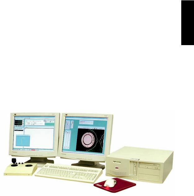
Overview System 1
Basic QC5200 for video systems or microscopes with joystick part positioning
2 |
QC5200 Series User’s Guide |
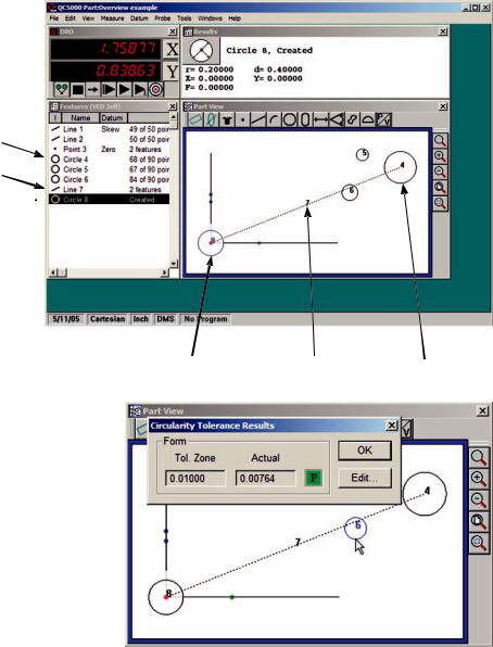
Part features can be measured, constructed from measured features, created from user data, copied from existing features or imported from .dxf, .igs and other files
Measured feature
Constructed feature
Created feature
Created feature |
Constructed feature |
Measured feature |
Geometric tolerances include location, form, orientation, runout and size. In addition, tolerances can be applied to groups of selected features.
Tolerances are context sensitive. For example, straightness is provided for lines and circularity is provided for circles. Tolerances can be displayed for evaluation and the tolerance criteria can be edited with a few clicks of the mouse, as shown in this example of a form tolerance
System Overview
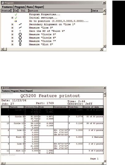
Programs can be created in manual systems to semi-automate repetitive tasks and simplify operator interactions, or in systems that include CNC control to automate measurements eliminating measurement errors and increasing throughput. Programs can be recorded automatically as a series of measurements are performed, can be created to include conditional branching and messages, can be edited in static or single-step modes and can be created from imported CAD files. The task of
programming is simplified by programming wizards and a comprehensive program debugging environment
Reports can be custom-formatted in a wide variety of formats to satisfy the requirements of different audiences by simply dragging and dropping data selections into templates. Templates can easily be customized. Completed reports can be archived, printed, ex- portedorsavedfore-mailing. Exported data can be sent to CAD applications, Microsoft Excel and Microsoft Access for processing
The user interface conforms to standard Windows conventions and can be quickly mastered by experienced Windows users. Task-specific menus, icons and toolbars further simplify in-
teractions with QC5200 features and measurement functions. Many aspects of the user interface can be customized to suit the needs of each user. Customized arrangements of windows and toolbars can be saved as unique workspaces to facilitate the most efficient use of the system by different users
This User’s Guide can be accessed and displayed from the Help menu, and includes links from all page references in the Table of Contents and Index to Guide content
3
System 1 Overview
4 |
QC5200 Series User’s Guide |

Chapter 2:
User Interface
The QC5200 user interface is a workspace consisting of windows, toolbars and a statusbar. The overall appearance of the user interface can vary greatly and can be customized to satisfy the requirements and personal preferences of the user. The following pages contain a detailed description of the QC5200 user interface. Here’s what you’ll find in this chapter
Introduction |
7 |
Windows |
8 |
Menus |
9 |
Toolbars |
9 |
Statusbar |
0 |
Windows |
|
DRO window |
2 |
Part View window |
|
Live Video window |
5 |
Results window |
7 |
Template Windows |
8 |
Stacking and separating templates |
8 |
Adding and deleting template content |
9 |
Features template |
20 |
Program template |
20 |
Report template |
20 |
Tolerance templates |
2 |
Menus |
22 |
Menubar menus |
22 |
File menu |
23 |
Edit menu |
25 |
View menu |
29 |
Measure menu |
35 |
Datum menu |
35 |
Probe menu |
35 |
Tools menu |
36 |
Windows menu |
39 |
5
Interface User 2
6 |
QC5200 Series User’s Guide |
|
|
On-screen |
4 |
|
Template window menus |
4 |
|
Template edit menus |
4 |
|
Program edit menus |
44 |
|
Results window menus |
46 |
|
Part View window menus |
50 |
|
Live Video window menus |
5 |
|
Toolbar menus |
53 |
|
Toolbars |
55 |
|
Changing toolbar shape |
56 |
|
Docking and undocking toolbars |
56 |
|
Customizing and creating toolbars |
57 |
|
Workspaces |
59 |
|
Creating custom workspaces |
59 |
|
Saving custom workspaces |
60 |
|
Opening custom workspaces |
60 |
|
Launching the QC5200 program into a specific workspace |
6 |
Introduction
Introduction
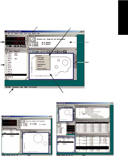
The QC5200 user interface is a workspace consisting of windows, menus, toolbars and a statusbar. The overall appearance of the user interface can vary greatly and can be customized to satisfy the requirements and personal preferences of the user. However, the individual elements of every workspace are consistent in purpose and function, and do not significantly change. Workspace elements include
•The DRO, Template, Results, Part View and Live Video windows
•Menu bar and on-screen menus
•Toolbars
• Statusbar |
Menubar menus |
On-screen menu |
|
DRO window |
Results window |
|
|
Toolbar docked |
Template window |
|
to the |
|
||
|
Part View window |
|
|
|
Statusbar |
Part View window |
The overall appearance of the user interface, or workspace, can be customized to vary greatly as shown here, but individual workspace elements remain essentially unchanged
7
Interface User 2

8 |
QC5200 Series User’s Guide |
Windows
Four window types are used to present numeric, text and graphic information:
• DRO • Templates • Results • Part View • Live Video
DRO
The Digital Readout (DRO) presents numeric position information for each axis
Templates
Template windows present tabular data describing features, programs, runs database contents and tolerance measurements. The template windows shown here are stacked. However, each window can be presented alone
Results
The Results window contains measurement data related to a feature selected in a template or in the Part View window
Part View
The Part View window contains a graphic display of the measurement reference frame and measured features
Live Video
The Part View window contains a real-time display of the video camera image including the part view at the active magnification with the active video probe superimposed over the part image
 Loading...