


Oktober 1995
User's Manual
ISO Programming
TNC 426
TNC 425
TNC 415 B
TNC 407
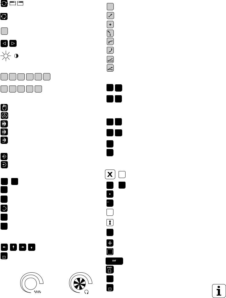
Controls on the TNC 426, TNC 425, TNC 415 B and TNC 407
Controls on the visual display unit
Toggle display between machining and programming modes
GRAPHICS Split screen layout
TEXT
SPLIT
SCREEN
Soft keys for selecting functions in screen
Shift keys for the soft keys
Brightness, contrast
Typewriter keyboard for entering letters and symbols
Q W E R T Y File names/ comments
G F S T M ... ISO
programming
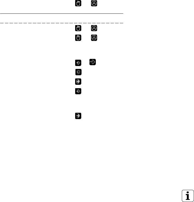
Machine operating modes
MANUAL OPERATION
EL. HANDWHEEL
POSITIONING WITH MDI
PROGRAM RUN/SINGLE BLOCK
PROGRAM RUN/FULL SEQUENCE
Programming modes
PROGRAMMING AND EDITING
TEST RUN
Program and file management
PGM |
PGM |
Select programs and files |
|
|
MGT |
NAME |
|
||
CL |
|
Delete programs and files (not on TNC 426) |
||
PGM |
|
|||
PGM |
|
Enter program call in a program |
||
CALL |
|
|||
EXT |
|
External data transfer (not on TNC 426) |
||
|
|
|||
MOD |
|
MODfunctions |
|
|
CALC |
|
Pocket calculator (TNC 426 only) |
||
Moving the cursor and going directly to |
|
|||
blocks, cycles and parameter functions |
|
|||
|
|
Move the cursor (highlight) |
||
GOTO |
|
Go directly to blocks, cycles and |
||
|
|
parameter functions |
|
|
Override control knobs |
|
|
||
|
|
100 |
|
100 |
Feed rate |
Spindle speed |
|
||
|
50 |
150 |
50 |
150 |
|
|
F % |
|
S % |
|
|
0 |
|
0 |
Programming path movements
(conversational programming only)
APPR |
|
Approach/depart contour |
DEP |
|
|
|
|
|
L |
|
Straight line |
CC |
|
Circle center/pole for polar coordinates |
|
|
|
C |
|
Circle with center |
|
|
|
CR |
|
Circle with radius |
|
|
|
CT |
|
Tangential circle |
|
|
|
CHF |
|
Chamfer |
|
|
|
RND |
|
Corner rounding |
|
|
|
Tool functions (conversational programming only) |
||
TOOL |
TOOL |
Enter or call tool length and radius |
DEF |
CALL |
|
R |
L |
Activate tool radius compensation (not on TNC 426) |
R+ |
R- |
|
Cycles, subprograms and program section repeats
(conversational programming only)
CYCL |
CYCL |
Define and call cycles |
||
DEF |
CALL |
|
||
LBL |
LBL |
|
Enter and call labels for subprogramming |
|
|
and program section repeats |
|||
SET |
CALL |
|||
STOP |
|
|
Enter program stop in a program |
|
TOUCH |
|
|
Enter touch probe functions in a program |
|
PROBE |
|
|
|
|
Coordinate axes and numbers, editing |
||||
|
|
... |
V |
Select coordinate axes or enter |
|
|
them into a program |
||
|
|
|
|
|
0 ... |
9 |
Numbers |
||
|
|
|
|
Decimal point |
/ |
+ |
|
|
Arithmetic sign |
|
|
|
|
|
P |
|
|
Polar coordinates |
|
|
|
|
|
Incremental dimensions |
Q |
|
|
Q parameters for part families or |
|
|
|
mathematicalfunctions |
||
|
|
|
|
Capture actual position |
NO |
|
|
Skip dialog questions, delete words |
|
ENT |
|
|
||
|
|
|
||
|
|
|
|
Confirm entry and resume dialog |
|
|
|
|
End block |
CE |
|
|
Clear numerical entry or TNC message |
|
|
|
|
||
DEL |
|
|
Abort dialog, delete program sections |
|
TNC Guideline
From the workpiece drawing to program-controlled machining
Step |
Task |
TNC operating |
Section in |
|
|
mode |
manual |
|
Preparation |
|
|
|
|
|
|
1 |
Select tools |
—— |
—— |
|
|
|
|
2 |
Set workpiece datum for |
|
|
|
coordinate system |
—— |
—— |
|
|
|
|
3 |
Determine spindle speeds |
|
|
|
and feed rates |
—— |
—— |
|
|
|
|
4 |
Switch on the machine |
—— |
1.3 |
|
|
|
|
5 |
Cross over reference marks |
or |
1.3, 2.1 |
|
|
|
|
|
|
|
|
6 |
Clamp workpiece |
—— |
—— |
7Set datum /
Reset position display ...
7a |
... with 3D touch probe |
or |
2.5 |
|
|
|
|
|
|
|
|
7b |
... without 3D touch probe |
or |
2.3 |
|
|
|
|
|
|
|
|
|
Entering and testing part programs |
|
|
|
|
|
|
8 |
Enter part program or download |
or |
|
|
over external data interface |
5 to 8, 9 |
|
|
|
||
|
|
|
|
9 |
Test part program for errors |
|
|
|
|
|
3.1 |
|
|
|
|
10 |
Test run: Run the program |
|
|
|
block by block without tool |
|
3.2 |
|
|
|
|
11 |
Optimize the part program |
|
|
|
(if necessary) |
|
5 to 8 |
|
|
|
|
|
Machining the workpiece |
|
|
|
|
|
|
12 |
Insert tool and run program |
|
3.2 |
|
|
|
|

How to use this manual
This manual describes functions and features available on TNCs as of the following NC software numbers:
|
|
|
NC Software No. |
TNC 407 |
|
|
280 580 04 |
|
|
|
|
TNC 415 B, TNC 425 |
|
280 540 04 |
|
|
|
|
|
TNC 415 |
F, TNC 425 E |
280 560 04 |
|
|
|
|
|
TNC 426 |
CA, TNC 426 |
PA |
280 462 01 |
|
|
|
|
TNC 426 CE, TNC 426 |
PE |
280 482 01 |
|
|
|
|
|
The suffixes E and F indicate export versions of the TNC.
The export versions TNC 415 F, TNC 425 E, TNC 426 CE, and
TNC 426 PE have the following limitations:
•Input and machining accuracy are limited to 1 µm
•Simultaneous linear movement in up to 4 axes
Some of the functions described in this manual are not available on all
TNCs. These functions are marked with symbols:
407
415
425
426
Function not available on the TNC 407
Function not available on the TNC 415
Function not available on the TNC 425
Function not available on the TNC 426
The machine manufacturer adapts the features offered by the TNC to the capabilities of the specific machine tool by setting machine parameters. This means that not every machine tool will have all of the functions described in this manual.
Some of the TNC functions which are not available on every machine are:
•Probe functions for the 3D touch probe
•Digitizing option (conversational programming only)
•Measuring tools with the TT 120 touch probe
(conversational programming only)
•Rigid tapping
•Re-approaching a contour after an interruption
Your machine manual provides more detailed information. If you think a function may be unavailable because of a defect, please contact the machine tool builder.
Many machine manufacturers and HEIDENHAIN offer programming courses for the TNCs. We recommend these courses as an effective way of improving your programming skill and sharing information and ideas with other TNC users.
TNC 426/TNC 425/TNC 415 B/TNC 407

This manual is intended both for the TNC beginner and the TNC expert.
The TNC beginner can use it as a step-by-step workbook. The manual begins with an explanation of the basics of numerical control (NC) and provides a glimpse into their application in the TNC. It then introduces the technique of conversational programming. All of the examples can be practiced directly on the TNC. Each function is explained thoroughly when it is used for the first time.
The TNC beginner should work through this manual completely from beginning to end to ensure that he is capable of fully exploiting the features of this powerful tool.
The TNC expert can use the manual as a comprehensive review and reference work. The table of contents and numerous cross references help him quickly find the topics and information he needs. Easy-to-read dialog flowcharts show him how to enter data for the desired function.
The dialog flowcharts aid the beginner by providing a description of the function of each key in a box to its right. If the user already knows the keys, he can concentrate on the illustrated input overview at the left of the flowchart. The TNC dialog messages are represented in shaded boxes above the answering input sequence.
TNC 426/TNC 425/TNC 415 B/TNC 407
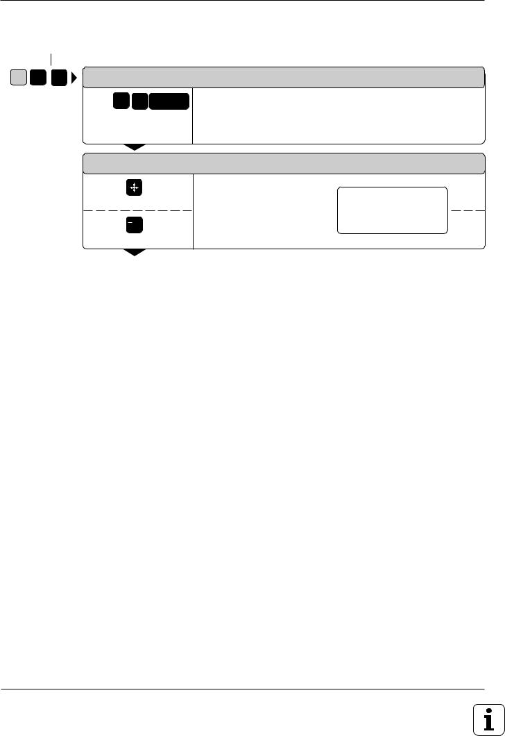
Layout of the dialog flowcharts
Dialog initiation key
G 8 3 |
DIALOG PROMPT (ON THE TNC SCREEN) |
||
|
e.g. 8 3 |
ENT |
Here the manual explains the function of the keys. |
|
|
|
|
|
Answer the prompt with |
|
|
|
these keys |
|
|
|
NEXT DIALOG PROMPT |
|
|
Press this key
+/
Or this key
Function of the key
|
|
|
|
|
|
|
|
|
|
|
|
|
|
|
|
|
|
|
|
|
|
|
|
A broken line indicates that |
|||||
|
|
|
|
|
|
|
|
|
|
|
|
|
|
|
|
|
|
|
|
|
|
|
|
eit |
her the key a |
bov |
e it |
or |
|
|
|
|
|
|
|
|
|
|
|
|
|
|
|
|
|
|
|
|
|
|
|
|
|
|
|||||
Function of the alternative key |
below it can be pressed. |
||||||||||||||||||||||||||||
.
.
.
The trail of points means that:
•the dialog is not completely illustrated, or
•the dialog continues on the next page.
Abbreviated dialog flowcharts
In abbreviated flowcharts an arrow ( ) is used to indicate new entries or work steps.
TNC 426/TNC 425/TNC 415 B/TNC 407

Contents User's Manual TNC 407, TNC 415 B, TNC 425, TNC 426 (280 5x0-xx, 280 462-xx)
ISO Programming
Introduction
Manual Operation and Setup
Test Run and Program Run
Programming
Programming Tool Movements
Subprograms and Program Section Repeats
Programming with Q Parameters
Cycles
External Data Transfer
MOD-Functions
Tabels, Overviews and Diagrams
1
2
3
4
5
6
7
8
9
10
11

1 |
Introduction |
|
|
|
1.1 |
The TNC 400 Series ............................................................................ |
1-2 |
|
|
Keyboard........................................................................................................................ |
1-4 |
|
|
Visual display unit .......................................................................................................... |
1-5 |
|
|
TNC Accessories ........................................................................................................... |
1-9 |
|
1.2 |
Fundamentals of NC ......................................................................... |
1-10 |
|
|
Introduction .................................................................................................................. |
1-10 |
|
|
What is NC? ................................................................................................................. |
1-10 |
|
|
The part program ......................................................................................................... |
1-10 |
|
|
Programming ............................................................................................................... |
1-10 |
|
|
Reference system ........................................................................................................ |
1-11 |
|
|
Cartesian coordinate system ....................................................................................... |
1-11 |
|
|
Additional axes............................................................................................................. |
1-12 |
|
|
Polar coordinates ......................................................................................................... |
1-12 |
|
|
Setting the pole ............................................................................................................ |
1-13 |
|
|
Datum setting ............................................................................................................... |
1-13 |
|
|
Absolute workpiece positions....................................................................................... |
1-15 |
|
|
Incremental workpiece positions .................................................................................. |
1-15 |
|
|
Programming tool movements ..................................................................................... |
1-18 |
|
|
Position encoders ........................................................................................................ |
1-18 |
|
|
Reference marks ......................................................................................................... |
1-18 |
|
1.3 |
Switch-On .......................................................................................... |
1-19 |
|
1.4 |
Graphics and Status Displays ......................................................... |
1-20 |
|
|
Graphics during program run ....................................................................................... |
1-20 |
|
|
Plan view...................................................................................................................... |
1-21 |
|
|
Projection in 3 planes................................................................................................... |
1-22 |
|
|
Cursor position during projection in 3 planes ............................................................... |
1-23 |
|
|
3D view ........................................................................................................................ |
1-23 |
|
|
Magnifying details ........................................................................................................ |
1-25 |
|
|
Repeating graphic simulation....................................................................................... |
1-26 |
|
|
Measuring the machining time ..................................................................................... |
1-26 |
|
|
Status displays ............................................................................................................. |
1-27 |
|
|
Additional status displays............................................................................................. |
1-27 |
|
1.5 |
File Management on the TNC 426 ................................................... |
1-30 |
|
|
Data security ................................................................................................................ |
1-30 |
|
|
Calling the file manager ............................................................................................... |
1-31 |
|
|
Functions for file management..................................................................................... |
1-35 |
|
|
Selecting file types ....................................................................................................... |
1-36 |
|
|
To copy individual files ................................................................................................. |
1-36 |
|
|
To copy several files into another directory ................................................................. |
1-37 |
|
|
To erase a file .............................................................................................................. |
1-38 |
|
|
To rename a file ........................................................................................................... |
1-38 |
|
|
To protect a file ............................................................................................................ |
1-38 |
|
|
To cancel file protection ............................................................................................... |
1-38 |
|
|
To convert a file ........................................................................................................... |
1-39 |
TNC 426/TNC 425/TNC 415 B/TNC 407

1.6 |
File Management on the TNC 425, TNC 415 B and TNC 407 ........ |
1-40 |
|
File directory ................................................................................................................ |
1-40 |
|
File status ..................................................................................................................... |
1-41 |
|
Selecting a file .............................................................................................................. |
1-41 |
|
To copy a file ................................................................................................................ |
1-42 |
|
To erase a file .............................................................................................................. |
1-42 |
|
To rename a file ........................................................................................................... |
1-42 |
|
To protect a file ............................................................................................................ |
1-42 |
|
To cancel file protection ............................................................................................... |
1-42 |
|
To convert a file ........................................................................................................... |
1-43 |
|
File management for files on external data media ....................................................... |
1-43 |
TNC 426/TNC 425/TNC 415 B/TNC 407

2 |
Manual Operation and Setup |
|
|
2.1 Moving the Machine Axes ................................................................... |
2-2 |
|
Traversing with the machine axis direction buttons................................................... |
2-2 |
|
Traversing with an electronic handwheel .................................................................. |
2-3 |
|
Using the HR 330 electronic handwheel ................................................................... |
2-3 |
|
Incremental jog positioning ........................................................................................ |
2-4 |
|
Positioning with manual data input (MDI) .................................................................. |
2-4 |
|
2.2 Spindle Speed S, Feed Rate F and Miscellaneous Functions M ..... |
2-5 |
|
To enter the spindle speed S .................................................................................... |
2-5 |
|
To change the spindle speed S ................................................................................. |
2-5 |
|
To change the feed rate F ......................................................................................... |
2-6 |
|
To enter a miscellaneous function M ......................................................................... |
2-6 |
|
2.3 Setting the Datum Without a 3D Touch Probe .................................. |
2-7 |
|
Setting the datum in the tool axis .............................................................................. |
2-7 |
|
To set the datum in the working plane ...................................................................... |
2-8 |
|
2.4 3D Touch Probes ................................................................................. |
2-9 |
|
3D Touch probe applications ..................................................................................... |
2-9 |
|
To select the touch probe functions .......................................................................... |
2-9 |
|
Calibrating the 3D touch probe ................................................................................ |
2-10 |
|
Compensating workpiece misalignment .................................................................. |
2-12 |
|
2.5 Setting the Datum with a 3D Touch Probe ...................................... |
2-14 |
|
To set the datum in an axis ..................................................................................... |
2-14 |
|
Corner as datum ...................................................................................................... |
2-15 |
|
Circle center as datum ............................................................................................ |
2-17 |
|
2.6 Measuring with a 3D Touch Probe ................................................... |
2-20 |
|
To find the coordinates of a position on an aligned workpiece ................................ |
2-20 |
|
Finding the coordinates of a corner in the working plane ........................................ |
2-20 |
|
Measuring workpiece dimensions ........................................................................... |
2-21 |
|
Measuring angles .................................................................................................... |
2-22 |
|
2.7 Tilting the Working Plane ................................................................. |
2-24 |
|
Traversing reference points with tilted axes ............................................................ |
2-25 |
|
Setting the datum in a tilted coordinate system....................................................... |
2-25 |
|
Position display in the tilted system ......................................................................... |
2-25 |
|
Limitations on working with the tilting function ........................................................ |
2-25 |
|
To activate manual tilting ......................................................................................... |
2-26 |
TNC 426/TNC 425/TNC 415 B/TNC 407
3 |
Test Run and Program Run |
|
|
|
3.1 |
Test Run ............................................................................................... |
3-2 |
|
|
To run a program test ................................................................................................ |
3-2 |
|
|
To run a program test up to a certain block ............................................................... |
3-3 |
|
|
The display functions for test run .............................................................................. |
3-3 |
|
3.2 |
Program Run ........................................................................................ |
3-4 |
|
|
To run a part program ............................................................................................... |
3-4 |
|
|
Interrupting machining ............................................................................................... |
3-5 |
|
|
Moving machine axes during an interruption ............................................................. |
3-6 |
|
|
Resuming program run after an interruption ............................................................. |
3-6 |
|
|
Mid-program startup .................................................................................................. |
3-8 |
|
|
Returning to the contour ............................................................................................ |
3-9 |
|
3.3 |
Optional Block Skip ........................................................................... |
3-10 |
|
3.4 |
Blockwise Transfer: Testing and Running Long Programs .......... |
3-11 |
TNC 426/TNC 425/TNC 415 B/TNC 407

4 |
Programming |
|
|
|
4.1 |
Creating Part Programs ...................................................................... |
4-2 |
|
|
Layout of a program .................................................................................................. |
4-2 |
|
|
Editing functions ........................................................................................................ |
4-3 |
|
4.2 |
Tools ..................................................................................................... |
4-5 |
|
|
Setting the tool data .................................................................................................. |
4-5 |
|
|
Oversizes for lengths and radii: delta values ............................................................ |
4-6 |
|
|
Entering tool data into the program ........................................................................... |
4-7 |
|
|
Entering tool data in tables ........................................................................................ |
4-8 |
|
|
Tool data in tables ................................................................................................... |
4-10 |
|
|
Pocket table for tool changer ................................................................................... |
4-14 |
|
|
Calling tool data ....................................................................................................... |
4-15 |
|
|
Tool change ............................................................................................................. |
4-15 |
|
|
Automatic tool change: M101 .................................................................................. |
4-16 |
|
4.3 |
Tool Compensation Values .............................................................. |
4-17 |
|
|
Effect of tool compensation values .......................................................................... |
4-17 |
|
|
Tool radius compensation ....................................................................................... |
4-17 |
|
|
Machining corners ................................................................................................... |
4-19 |
|
4.4 |
Program Creation .............................................................................. |
4-20 |
|
|
Defining the blank form ........................................................................................... |
4-20 |
|
|
To create a new part program ................................................................................. |
4-21 |
|
4.5 |
Entering Tool-Related Data .............................................................. |
4-23 |
|
|
Feed rate F .............................................................................................................. |
4-23 |
|
|
Spindle speed S ...................................................................................................... |
4-24 |
|
4.6 |
Entering Miscellaneous Functions and Program Stop .................. |
4-25 |
|
4.7 |
Actual Position Capture .................................................................... |
4-26 |
|
4.8 |
Integrated Pocket Calculator ............................................................ |
4-27 |
|
4.9 |
Marking Blocks for Optional Block Skip ......................................... |
4-28 |
|
4.10 |
Text Files ............................................................................................ |
4-29 |
|
|
Finding text sections ................................................................................................ |
4-31 |
|
|
To erase and insert characters, words and lines ..................................................... |
4-32 |
|
|
Editing text blocks ................................................................................................... |
4-33 |
|
4.11 |
Creating Pallet Files .......................................................................... |
4-35 |
|
4.12 Adding Comments to the Program .................................................. |
4-37 |
|
|
|
Adding comments to program blocks ...................................................................... |
4-37 |
TNC 426/TNC 425/TNC 415 B/TNC 407

5 |
Programming Tool Movements |
|
|
5.1 General Information on Programming Tool Movements ................. |
5-2 |
|
5.2 Contour Approach and Departure ..................................................... |
5-4 |
|
Starting point and end point ...................................................................................... |
5-4 |
|
Tangential approach and departure .......................................................................... |
5-6 |
|
5.3 Path Functions..................................................................................... |
5-7 |
|
General information ................................................................................................... |
5-7 |
|
Machine axis movement under program control ....................................................... |
5-7 |
|
Overview of path functions ........................................................................................ |
5-9 |
|
5.4 Path Contours – Cartesian Coordinates ......................................... |
5-10 |
|
G00: Straight line with rapid traverse ...................................................................... |
5-10 |
|
G01: Straight line with feed rate F ... ....................................................................... |
5-10 |
|
G24: Chamfer .......................................................................................................... |
5-13 |
|
Circles and circular arcs .......................................................................................... |
5-15 |
|
Circle center I, J, K .................................................................................................. |
5-16 |
|
G02/G03/G05: Circular path around pole I, J, K ..................................................... |
5-18 |
|
G02/G03/G05: Circular path with defined radius..................................................... |
5-21 |
|
G06: Circular path with tangential connection ......................................................... |
5-24 |
|
G25: Corner rounding .............................................................................................. |
5-26 |
|
5.5 Path Contours – Polar Coordinates ................................................. |
5-28 |
|
Polar coordinate origin: Pole I, J, K ......................................................................... |
5-28 |
|
G10: Straight line with rapid traverse ..................................................................... |
5-28 |
|
G11: Straight line with feed rate F … ...................................................................... |
5-28 |
|
G12/G13/G15: Circular path around pole I, J, K ..................................................... |
5-30 |
|
G16: Circular path with tangential transition ............................................................ |
5-32 |
|
Helical interpolation ................................................................................................. |
5-33 |
|
5.6 M Functions for Contouring Behavior and Coordinate Data ........ |
5-36 |
|
Smoothing corners: M90 ......................................................................................... |
5-36 |
|
Machining small contour steps: M97 ....................................................................... |
5-37 |
|
Machining open contours: M98 ............................................................................... |
5-38 |
|
Programming machine-referenced coordinates: M91/M92 ..................................... |
5-39 |
|
Feed rate factor for plunging movements: M103 F… .............................................. |
5-40 |
|
Feed rate at circular arcs: M109/M110/M111 .......................................................... |
5-41 |
|
Insert rounding arc between straight lines: M112 E... ............................................. |
5-41 |
|
Automatic compensation of machine geometry when working with |
|
|
tilted axes: M114 ..................................................................................................... |
5-42 |
|
Feed rate in mm/min on rotary axes A, B, C: M116 ................................................ |
5-43 |
|
Reduce display of a rotary axis to a value less than 360°: M94 .............................. |
5-43 |
|
Optimized traverse of rotary axes: M126 ................................................................ |
5-44 |
|
5.7 Positioning with Manual Data Input: System File $MDI ................. |
5-45 |
TNC 426/TNC 425/TNC 415 B/TNC 407

6 Subprograms and Program Section Repeats
6.1 Subprograms ....................................................................................... |
6-2 |
Operating sequence .................................................................................................. |
6-2 |
Operating limitations .................................................................................................. |
6-2 |
Programming and calling subprograms ..................................................................... |
6-3 |
6.2 Program Section Repeats ................................................................... |
6-5 |
Operating sequence .................................................................................................. |
6-5 |
Programming notes ................................................................................................... |
6-5 |
Programming and executing a program section repeat ............................................ |
6-5 |
6.3 Program as Subprogram .................................................................... |
6-8 |
Operating sequence .................................................................................................. |
6-8 |
Operating limitations .................................................................................................. |
6-8 |
Calling a program as a subprogram .......................................................................... |
6-8 |
6.4 |
Nesting ................................................................................................. |
6-9 |
|
Nesting depth ............................................................................................................ |
6-9 |
|
Subprogram within a subprogram ............................................................................. |
6-9 |
|
Repeating program section repeats ........................................................................ |
6-11 |
|
Repeating subprograms .......................................................................................... |
6-12 |
TNC 426/TNC 425/TNC 415 B/TNC 407

7 |
Programming with Q Parameters |
|
|
|
7.1 |
Part Families — Q Parameters in Place of Numerical Values |
.........7-4 |
|
7.2 |
Describing Contours Through Mathematical Functions ................. |
7-7 |
|
|
Overview ................................................................................................................... |
7-7 |
|
7.3 |
Trigonometric Functions .................................................................. |
7-10 |
|
|
Overview ................................................................................................................. |
7-10 |
|
7.4 |
If-Then Decisions with Q Parameters .............................................. |
7-11 |
|
|
Jumps .................................................................................................................. |
7-11 |
|
|
Overview ................................................................................................................. |
7-11 |
|
7.5 |
Checking and Changing Q Parameters ........................................... |
7-13 |
|
7.6 |
Diverse Functions ............................................................................. |
7-14 |
|
|
Displaying error messages ...................................................................................... |
7-14 |
|
|
Output through an external data interface ............................................................... |
7-16 |
|
|
Formatted output of texts and Q parameter values ................................................. |
7-17 |
|
|
Reading system data ............................................................................................... |
7-18 |
|
|
Transfer to the PLC ................................................................................................. |
7-19 |
|
7.7 |
Entering Formulas Directly............................................................... |
7-20 |
|
|
Overview of functions .............................................................................................. |
7-20 |
|
7.8 |
Measuring with the 3D Touch Probe During Program Run ........... |
7-23 |
|
7.9 |
Programming Examples ................................................................... |
7-25 |
|
|
Rectangular pocket with island, corner rounding and tangential approach ............. |
7-25 |
|
|
Bolt hole circles ....................................................................................................... |
7-27 |
|
|
Ellipse .................................................................................................................. |
7-29 |
|
|
Hemisphere machined with end mill ........................................................................ |
7-31 |
TNC 426/TNC 425/TNC 415 B/TNC 407

8 |
Cycles |
|
|
|
8.1 General Overview of Cycles ............................................................... |
8-2 |
|
|
|
Programming a cycle ................................................................................................. |
8-2 |
|
|
Dimensions in the tool axis ........................................................................................ |
8-3 |
|
8.2 |
Simple Fixed Cycles ............................................................................ |
8-4 |
|
|
PECKING (G83) ........................................................................................................ |
8-4 |
|
|
TAPPING with floating tap holder (G84) ................................................................... |
8-6 |
|
|
RIGID TAPPING (G85) ............................................................................................. |
8-8 |
|
|
THREAD CUTTING (G86) ........................................................................................ |
8-9 |
|
|
SLOT MILLING (G74) ............................................................................................. |
8-11 |
|
|
POCKET MILLING (G75/G76) ................................................................................ |
8-13 |
|
|
CIRCULAR POCKET MILLING (G77/G78) ............................................................. |
8-15 |
|
8.3 SL Cycles (Group I) ........................................................................... |
8-17 |
|
|
|
CONTOUR GEOMETRY (G37) .............................................................................. |
8-18 |
|
|
ROUGH-OUT (G57) ................................................................................................ |
8-19 |
|
|
Overlapping contours .............................................................................................. |
8-21 |
|
|
PILOT DRILLING (G56) .......................................................................................... |
8-27 |
|
|
CONTOUR MILLING (G58/G59) ............................................................................. |
8-28 |
|
8.4 SL Cycles (Group II) .......................................................................... |
8-31 |
|
|
|
CONTOUR DATA (G120) ....................................................................................... |
8-32 |
|
|
PILOT DRILLING (G121) ........................................................................................ |
8-33 |
|
|
ROUGH-OUT (G122) .............................................................................................. |
8-34 |
|
|
FLOOR FINISHING (G123) ..................................................................................... |
8-34 |
|
|
SIDE FINISHING (G124) ......................................................................................... |
8-35 |
|
|
CONTOUR TRAIN (G125) ...................................................................................... |
8-37 |
|
|
CYLINDER SURFACE G127 .................................................................................. |
8-39 |
|
8.5 |
Coordinate Transformations ............................................................ |
8-42 |
|
|
DATUM SHIFT (G54) .............................................................................................. |
8-43 |
|
|
DATUM SHIFT with datum tables (G53) ................................................................. |
8-45 |
|
|
MIRROR IMAGE (G28) ........................................................................................... |
8-48 |
|
|
ROTATION (G73) .................................................................................................... |
8-50 |
|
|
SCALING FACTOR (G72) ....................................................................................... |
8-51 |
|
8.6 |
Other Cycles ...................................................................................... |
8-53 |
|
|
DWELL TIME (G04) ................................................................................................ |
8-53 |
|
|
PROGRAM CALL (G39) .......................................................................................... |
8-53 |
|
|
ORIENTED SPINDLE STOP (G36) ........................................................................ |
8-54 |
|
|
WORKING PLANE (G80) ........................................................................................ |
8-55 |
TNC 426/TNC 425/TNC 415 B/TNC 407

9 |
External Data Transfer |
|
|
|
9.1 |
Data Transfer with the TNC 426 ......................................................... |
9-2 |
|
|
To copy individual files into the TNC ......................................................................... |
9-2 |
|
|
To copy multiple files into the TNC ............................................................................ |
9-3 |
|
|
Copying files out of the TNC ..................................................................................... |
9-3 |
|
9.2 |
Data Transfer with the TNC 425, TNC 415 B and TNC 407............... |
9-4 |
|
|
Selecting and transferring files .................................................................................. |
9-5 |
|
|
Blockwise transfer ..................................................................................................... |
9-6 |
|
9.3 |
Pin Layout and Connecting Cable for the Data Interfaces .............. |
9-7 |
|
|
RS-232-C/V.24 Interface ........................................................................................... |
9-7 |
|
|
RS-422/V.11 Interface ............................................................................................... |
9-9 |
|
9.4 |
Preparing the Devices for Data Transfer ......................................... |
9-10 |
|
|
HEIDENHAIN devices ............................................................................................. |
9-10 |
|
|
Non-HEIDENHAIN devices ..................................................................................... |
9-10 |
TNC 426/TNC 425/TNC 415 B/TNC 407

10 MOD Functions
10.1 |
Selecting, Changing and Exiting the MOD Functions |
...................10-3 |
10.2 |
Software Numbers and Option Numbers ........................................ |
10-3 |
10.3 |
Code Numbers ................................................................................... |
10-3 |
10.4 |
Setting the External Data Interfaces ................................................ |
10-4 |
|
Setting the RS-232 interface ................................................................................... |
10-4 |
|
Setting the RS-422 interface ................................................................................... |
10-4 |
|
Selecting the OPERATING MODE .......................................................................... |
10-4 |
|
Setting the BAUD RATE .......................................................................................... |
10-4 |
|
ASSIGN .................................................................................................................. |
10-5 |
10.5 |
Machine-Specific User Parameters .................................................. |
10-6 |
10.6 |
Showing the Workpiece in the Working Space .............................. |
10-6 |
|
Overview of functions .............................................................................................. |
10-7 |
10.7 |
Position Display Types ..................................................................... |
10-8 |
10.8 |
Unit of Measurement ......................................................................... |
10-9 |
10.9 |
Programming Language for $MDI .................................................... |
10-9 |
10.10 Selecting the Axes for Generating L Blocks |
|
|
|
(conversational programming only) ................................................ |
10-9 |
10.11 Axis Traverse Limits ....................................................................... |
10-10 |
|
10.12 HELP files ......................................................................................... |
10-11 |
|
TNC 426/TNC 425/TNC 415 B/TNC 407

11 Tables, Overviews and Diagrams
11.1 General User Parameters .................................................................. |
11-2 |
Input possibilities for machine parameters .............................................................. |
11-2 |
Selecting general user parameters ......................................................................... |
11-2 |
External data transfer .............................................................................................. |
11-3 |
3D touch probes and digitizing ................................................................................ |
11-4 |
TNC displays, TNC editor ........................................................................................ |
11-7 |
Machining and program run .................................................................................. |
11-13 |
Electronic handwheel ............................................................................................ |
11-15 |
11.2 |
Miscellaneous Functions (M Functions) ....................................... |
11-16 |
|
Miscellaneous functions with predetermined effect ............................................... |
11-16 |
|
Vacant miscellaneous functions ............................................................................ |
11-18 |
11.3 |
Preassigned Q Parameters ............................................................. |
11-19 |
11.4 |
Features, Specifications and Accessories.................................... |
11-21 |
|
Accessories ........................................................................................................... |
11-24 |
11.5 |
TNC Error Messages ....................................................................... |
11-26 |
|
TNC error messages during programming ............................................................ |
11-26 |
|
TNC error messages during test run and program run ......................................... |
11-27 |
11.6 |
Address Letters (ISO) ...................................................................... |
11-31 |
|
Parameter definitions ............................................................................................ |
11-34 |
TNC 426/TNC 425/TNC 415 B/TNC 407

1 Introduction
1.1 The TNC 400 Series
The TNCs are shop-floor programmable contouring controls for boring machines, milling machines and machining centers with up to 5 axes. They also feature oriented spindle stop.
Two operating modes are always active simultaneously: one for machine movements (machining modes) and one for programming or program testing (programming modes).
TNC 426
The TNC 426 PA features digital control of machine axis speed. This provides high geometrical accuracy, even with complex workpiece surfaces and at high machining speeds.
An integrated 170 megabyte hard disk provides storage for programs that were created on external devices. The TNC 426 also offers an on-screen pocket calculator.
TNC 425
The TNC 425 also features digital control of machine axis speed. This results in high geometrical accuracy, even with complex workpiece surfaces and at high machining speeds.
TNC 415 B
The TNC 415 B uses an analog method of speed control in the drive amplifier. All the programming and machining functions of the TNC 425 are also available on the TNC 415 B.
TNC 407
The TNC 407 uses an analog method of speed control in the drive amplifier. Some functions are not available on the TNC 407, such as:
•Graphics during program run
•Tilting the machining plane
•Linear movement in more than three axes
Technical differences between the TNCs
|
TNC 426 PA |
TNC 426 CA |
TNC 425 |
TNC 415 B |
TNC 407 |
Speed control |
Digital |
Analog |
Digital/analog Analog |
Analog |
|
|
|
|
|
|
|
Block processing time |
4 ms |
4 ms |
4 ms |
4 ms |
24 ms |
|
|
|
|
|
|
Control loop cycle time: |
|
|
|
|
|
Contouring interpolation |
3 ms |
3 ms |
3 ms |
2 ms |
6 ms |
|
|
|
|
|
|
Control loop cycle time: |
|
|
|
|
|
Fine interpolation |
0.6 ms |
--- |
0.6 ms |
0.6 ms |
--- |
|
|
|
|
|
|
Program memory |
170 M byte |
170 M byte |
256 K byte |
256 K byte |
128 K byte |
|
(hard disk) |
(hard disk) |
|
|
|
|
|
|
|
|
|
Input resolution |
0.1 µm |
0.1 µm |
0.1 µm |
0.1 µm |
1 µm |
|
|
|
|
|
|
1-2 |
TNC 426/TNC 425/TNC 415 B/TNC 407 |
1 Introduction
1.1The TNC 400 Series
Visual display unit and keyboard
The 14-inch color monitor displays all the information necessary for effective use of the TNC's capabilities.
The keys are grouped on the keyboard according to function. This makes it easier to create programs and to use the TNC’s functions.
Programming
The TNCs are programmed in ISO format.
It is also possible to program in easy-to-understand HEIDENHAIN conversational format (a separate User's Manual is available for this).
Graphics
Workpiece machining can be graphically simulated both during machining (except on TNC 407) or before actual machining. Various display modes are available.
Compatibility
The TNCs can execute all part programs written on HEIDENHAIN TNC 150 B controls or later.
TNC 426/TNC 425/TNC 415 B/TNC 407 |
1-3 |
1Introduction
1.1The TNC 400 Series
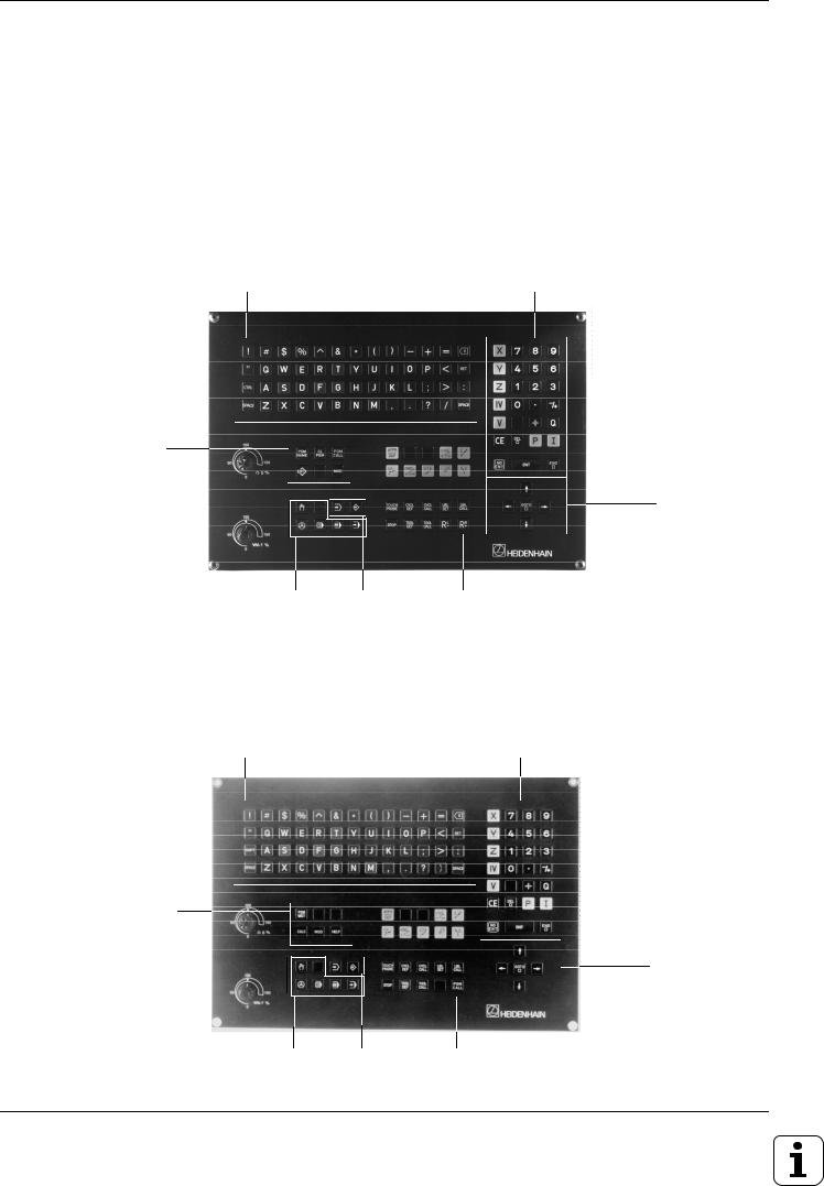
Keyboard
The keys on the TNC keyboard are marked with symbols and abbreviations that make them easy to remember. They are grouped according to the their functions. The functions of the individual keys are described in the front cover fold-out of the TNC user's manual. A description of machine panel buttons is provided in the manual for your machine tool.
The keyboard of TNC 407, TNC 415 and TNC 425 controls
Typewriter-style keyboard for entering file names, comments and other texts, as well as programming in ISO format
Program and file management
Machine operating modes
Numerical input and axis selection
Arrow keys and
GOTO key
Programming |
Dialog initiation for |
modes |
conversational |
|
programming |
The keyboard of TNC 426 controls
Typewriter-style keyboard for entering file names, comments and other texts, as well as programming in ISO format
File management, pocket calculator, MOD functions, HELP functions
Machine operating modes
Numerical input and axis selection
Arrow keys and
GOTO key
Programming |
Dialog initiation |
modes |
|
1-4 |
TNC 426/TNC 425/TNC 415 B/TNC 407 |
1 Introduction
1.1The TNC 400 Series
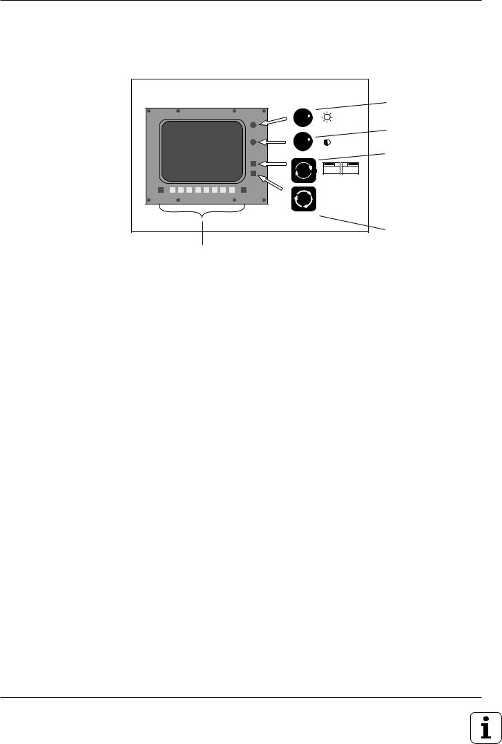
Visual display unit
GRAPHICS |
TEXT |
SPLIT |
SCREEN |
Soft keys with context-specific functions, and two shift keys for additional soft-key rows
Brightness control
Contrast control
Switchover between the active programming and machining modes
SPLIT SCREEN key for switching screen layout (see page 1-6)
Headline
The two selected TNC modes are shown in the screen headline:
the machining mode to the left and the programming mode to the right. The currently active mode is displayed in the larger box, where dialog prompts and TNC messages also appear.
Soft keys
The soft keys select the functions shown in the soft-key row immediately above them. The shift keys to the right and left call up additional soft-key rows. Colored lines above the soft-key row indicate the number of available rows. The line representing the active row is highlighted.
TNC 426/TNC 425/TNC 415 B/TNC 407 |
1-5 |
1 Introduction
1.1The TNC 400 Series
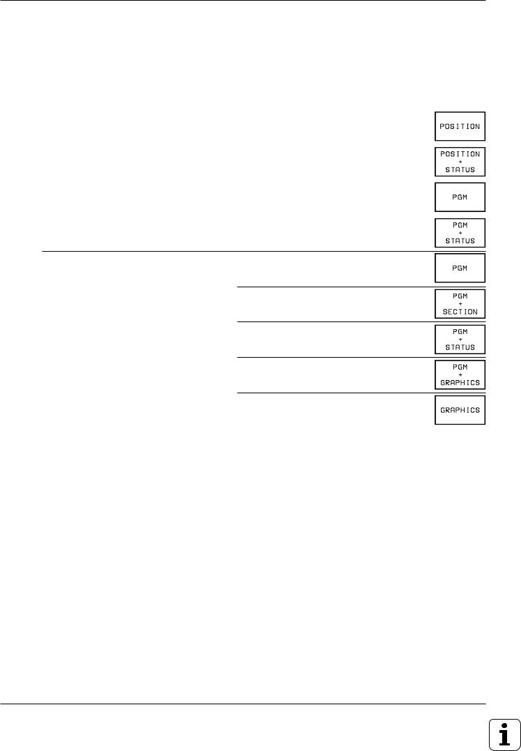
Screen layout
You can select the type of display on the TNC screen by pressing the SPLIT SCREEN key and one of the soft keys listed below. Depending on the active mode of operation, you can select:
Mode of operation |
Screen layout |
Soft key |
MANUAL |
Positions |
|
ELECTRONIC HANDWHEEL |
|
|
|
|
|
|
Left: positions |
|
|
Right: STATUS |
|
|
|
|
POSITIONING WITH MDI |
Program blocks |
|
|
|
|
|
Left: program blocks |
|
|
Right: STATUS |
|
PROGRAM RUN/FULL SEQUENCE PROGRAM RUN/SINGLE BLOCK TEST RUN
Program blocks
Left: program blocks Right: program structure
(conversational programming only)
Left: program blocks
Right: STATUS
Left: program blocks
Right: graphics
|
Graphics |
|
|
PROGRAMMING AND EDITING |
No screen selection possible, the TNC |
|
displays program blocks only |
|
|
1-6 |
TNC 426/TNC 425/TNC 415 B/TNC 407 |

1 |
Introduction |
1.1 |
The TNC 400 Series |
Screen layout of modes |
|
PROGRAMMING AND EDITING: |
|
Machining |
|
mode |
Programming mode is selected |
Text of the selected program
Soft-key row
TEST RUN:
Machining |
Programming mode is selected |
mode |
Text of the |
|
|
|
Graphics |
|
|
|
||
selected |
|
|
|
(or additional |
program |
|
|
|
status display) |
Soft-key row
TNC 426/TNC 425/TNC 415 B/TNC 407 |
1-7 |

1 Introduction
1.1The TNC 400 Series
MANUAL OPERATION and ELECTRONIC HANDWHEEL modes:
A machining mode is |
Programming |
selected |
mode |
•Coordinates
•Selected axis
•means TNC in operation
•Status display, e.g. feed rate F, miscellaneous function M, symbols for basic
rotation and/or tilted working plane
PROGRAM RUN/FULL SEQUENCE, PROGRAM RUN/SINGLE BLOCK
A machining mode is |
Programming |
selected |
mode |
Additional status display
Soft-key row
Text of the
selected |
|
Graphics |
|
||
|
(or additional |
|
program |
|
|
|
status display, |
|
|
|
|
|
|
or program |
|
|
structure) |
Status display
Soft-key row
1-8 |
TNC 426/TNC 425/TNC 415 B/TNC 407 |
1Introduction
1.1The TNC 400 Series
TNC Accessories
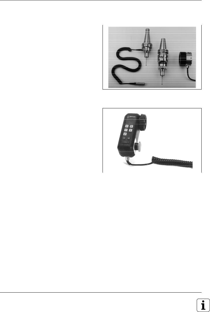
3D Touch Probe Systems
The TNC provides the following features when used in conjunction with a HEIDENHAIN 3D touch probe:
•Electronic workpiece alignment (compensation of workpiece misalignment)
•Datum setting
•Measurement of the workpiece during program run
•Digitizing 3D surfaces (optional, only available with conversational programming)
•Measuring tools with the TT 120 touch probe (only available)
Fig. 1.6: TS 220 and TS 630 3D-touch probes
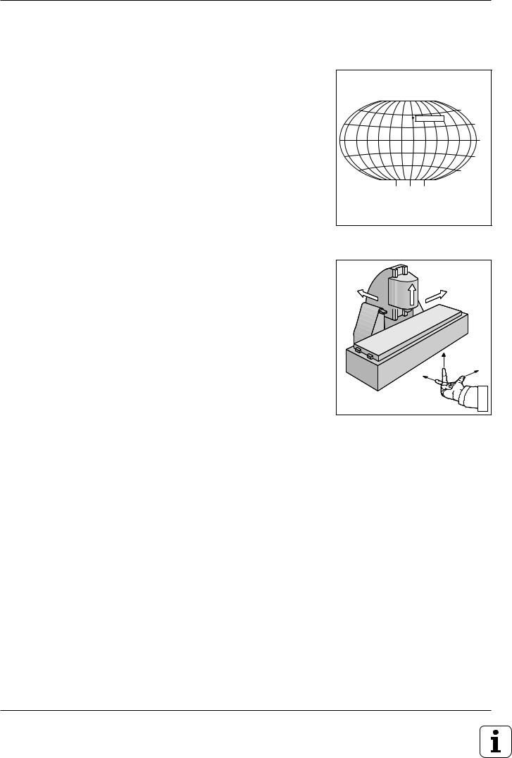
Electronic Handwheels
Electronic handwheels facilitate precise manual control of the axis slides. Similar to a conventional machine tool, the machine slide moves in direct relation to the rotation of the handwheel. A wide range of traverses per handwheel revolution is available.
Portable handwheels such as the HR 330 are connected via cable to the TNC. Integral handwheels such as the HR 130 are built into the machine control panel. An adapter permits connection of up to three handwheels.
Your machine manufacturer can tell you more about the handwheel configuration of your machine.
Fig. 1.7: HR 330 electronic handwheel
TNC 426/TNC 425/TNC 415 B/TNC 407 |
1-9 |

1 Introduction
1.2 Fundamentals of NC
Introduction
This chapter discusses the following topics:
•What is NC?
•The part program
•Programming
•Reference system
•Cartesian coordinate system
•Additional axes
•Polar coordinates
•Setting the pole
•Datum setting
•Absolute workpiece positions
•Incremental workpiece positions
•Programming tool movements
•Position encoders
•Reference marks
What is NC?
NC stands for Numerical Control, that is, the operation of a machine tool by a series of coded instructions comprised of numbers. Modern controls such as the TNC have a built-in computer for this purpose and are therefore called CNC (Computerized Numerical Control).
The part program
The part program is a complete list of instructions for machining a part.
It contains such information as the target position of a tool movement, the path function (how the tool should move toward the target position) and the feed rate. Information on the radius and length of the tool, spindle speed and tool axis must also be included in the program.
Programming
ISO programming is partially dialog-guided. The programmer is free to enter the individual commands (words) in each block in any sequence (except with G90/G91). The commands are automatically sorted by the TNC when the block is concluded.
1-10 |
TNC 426/TNC 425/TNC 415 B/TNC 407 |
1 Introduction
1.2Fundamentals of NC
Reference system
In order to define positions, a reference system is necessary. For example, positions on the earth's surface can be defined “absolutely” by their geographic coordinates of longitude and latitude. The word coordinate comes from the Latin word for “that which is arranged.” The network of horizontal and vertical lines around the globe constitute an absolute reference system — in contrast to the relative definition of a position that is referenced to a known location.
60°
Greenwich
30°
0°
30°
60°
90° 0° 90°
Cartesian coordinate system
On a TNC-controlled milling machine, workpieces are normally machined according to a workpiece-based Cartesian coordinate system (a rectangular coordinate system named after the French mathematician and philosopher Renatus Cartesius, who lived from 1596 to 1650). The Cartesian coordinate system is based on three coordinate axes X, Y and Z which are parallel to the machine guideways.
The figure to the right illustrates the “right-hand rule” for remembering the three axis directions: the middle finger is pointing in the positive direction of the tool axis from the workpiece toward the tool (the Z axis), the thumb is pointing in the positive X direction, and the index finger in the positive Y direction.
Fig. 1.8: The geographic coordinate system is an absolute reference system
+Y |
+Z |
+X |
|
|
+X |
Fig. 1.9: Designations and directions of the axes on a milling machine
TNC 426/TNC 425/TNC 415 B/TNC 407 |
1-11 |

1 Introduction
1.2Fundamentals of NC
Additional axes
The TNC can control the machine in more than three axes. Axes U, V and W are secondary linear axes parallel to the main axes X, Y and Z, respectively (see illustration). Rotary axes are also possible, and are designated as A, B and C.
|
Z |
Y |
|
|
|
W+ |
C+ |
B+ |
|
||
|
|
V+ |
|
|
A+ |
|
|
X |
|
|
U+ |
Fig. 1.10: Direction and designation of additional axes
Polar coordinates |
Y |
|
|
|
Although the Cartesian coordinate system is |
|
|
|
|
especially useful for parts whose dimensions are |
|
R |
|
|
mutually perpendicular, in the case of parts contain- |
|
|
||
|
|
R |
||
ing circular arcs or angles it is often simpler to give |
|
H 2 |
||
the dimensions in polar coordinates. While Carte- |
|
|
||
|
H 3 |
|
||
sian coordinates are three-dimensional and can |
|
|
||
|
|
|
||
describe points in space, polar coordinates are two- |
|
R |
|
|
dimensional and describe points in a plane. |
|
|
H 1 |
|
|
J = 10 |
|
0° |
|
Polar coordinates have their datum at a pole I, J, K |
|
|
|
|
from which a position is measured in terms of its |
|
|
|
|
distance from the pole and the angle of its position |
|
|
|
|
in relation to the pole. |
|
I = 30 |
X |
|
You could think of polar coordinates as the result of |
Fig. 1.11: |
Identifying positions on a circular arc with polar coordinates |
||
a measurement using a scale whose zero point is |
||||
|
|
|
||
fixed at the datum and which you can rotate to |
|
|
|
|
different angles in the plane around the pole. |
|
|
|
|
The positions in this plane are defined by the
•Polar Radius R, the distance from the circle center I, J to the position, and the
•Polar Angle H, the size of the angle between the reference axis and the scale.
1-12 |
TNC 426/TNC 425/TNC 415 B/TNC 407 |
 Loading...