


 Loading...
Operating Instructions
ND 1200 QUADRA-CHEK
Software Version 2.16
English (en) 4/2009

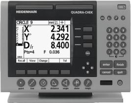
ND 1200 Introduction
1LCD screen
2Soft keys
3Measurement function keys
4Axis keys
5Mode selection keys
6Command keys
7Menu key
8Arrow cursor keys
9Fast track keys
10Numeric keypad
11Send key
12LCD On/Off key
ND 1200 panel keys
Panel keys are used to initiate feature measurements, apply tolerances, send reports of measurement results and configure operational parameters.
Panel function key |
Panel key |
Soft keys: Functions change in support of the activities displayed on the LCD.
Measure keys: Select a feature measurement type. Feature measurement types include points, lines, circles distances, angles, skew alignments and Measure Magic.
Axis keys: Select axes for zeroing or presetting datums prior to measurements.
Mode keys: Select unit of measure, datum, cartesian or polar coordinate system and help.
Command keys: Control measurement and data entry processes.
ND 1200 QUADRA-CHEK |
3 |

Panel function key |
Panel key |
Menu key: Displays five soft key menus for system setup, programming, extra functions clearing data and optional optical edge detector functions.
Arrow cursor keys: Used to scroll through lists and navigate menus and setup screen data fields. The up arrow cursor key is also used to begin a feature construction process, as described later in the feature Constructions portion of this chapter.
Fast track keys: Two programmable fast track keys are used to perform frequently used functions. These keys can easily be located by touch without taking your eyes off the part. By default the left fast track key is assigned the Enter key function and the right is assigned the Finish key function. Users can program either fast track key as described later in the Hotkeys portion of Chapter 2: Installation, Setup and Specifications.
Numeric keypad: Used to enter numeric data. Additionally, the decimal point key and +/- key are used to adjust the contrast of the LCD display.
Send key: Used to transmit measurement results to a computer, USB printer or USB flash drive.
LCD On/Off key: Press the LCD on/off button to turn the LCD display off without removing power from the ND 1200. Press the button a second time to restore the LCD display. Additionally, the LCD On/Off key can be used to clear feature data, datums and skews.
4 |
Preface |

ND 1200 rear panel
1Serial number label
2Power switch
3Power cord connector and fuse holder
4Power ground access
5Measurement axis connectors
6RS-232 serial port connector
7Optical reference cable connector
8Optical sensor cable connector
9Not supported in the ND 1200
10Tilt base mechanical tightness adjustment
11Electrical Ratings label
ND 1200 side panel
1Speaker/headset jack
2USB Type A connector
3RJ-45 Foot switch/hand switch/keypad connector
ND 1200 QUADRA-CHEK |
5 |
Information contained in this manual
This User's manual covers the operation, installation, setup and specifications of the ND 1200. Operating information is contained in chapter 1. Installation, setup instructions and specifications are contained in chapter 2.
Fonts used in this manual
The following fonts are used to indicate operator controls or to show emphasis:
Operator controls - soft keys and other panel keys are shown in upper case.
Emphasis - Items of special interest or concepts that are emphasized to the user are shown in bold type.
Showing sequences of key presses
The ND 1200 user performs sequences of soft key and panel key presses to measure part features and complete other tasks. These sequences are indicated using text as shown in the following example:
Press the MENU key, press the EDGE soft key and then press the AUTO E soft key is sometimes abbreviated as:
Press MENU/EDGE/AUTO E
Symbols within notes
Notes are marked with symbols on the left indicating the type, or potential severity of the information.
General Information
This is additional or supplementary information about an activity or concept.
Warning
This warns of a situation or condition that could lead to measurement errors, equipment malfunction or equipment damage. Do not proceed until the message is read and understood.
Caution - Risk of electric shock
This warns of a situation or condition that could lead to electrical shock and to personal injury or death. Do not proceed until the message is read and understood.
6 |
Preface |

Safety considerations
General accepted safety precautions must be followed when operating the system. Failure to observe these precautions could result in damage to the equipment, or injury to personnel. It is understood that safety rules within individual companies vary. If a conflict exists between the material contained in this manual and the rules of a company using this system, the more stringent rules should take precedence.
The ND 1200 is equipped with a 3-wire power plug that includes a separate ground connection. Always connect the power plug to a 3-wire grounded outlet. Use of 2-wire power plug adapters or any other connection accessories that remove the third grounded connection create a safety hazard and should not be permitted.
Unplug the ND 1200 from the power outlet and seek the assistance of a qualified service technician if:
The power cord is frayed or damaged or the power plug is damaged
Liquid is spilled or splashed onto the enclosure
The ND 1200 has been dropped or the exterior has been damaged
The ND 1200 exhibits degraded performance or indicates a need for service some other way
ND 1200 measurement axes
The ND 1200 DRO can display 2, 3, or 4 axes depending on the model purchased. DRO screen images used throughout this manual show different numbers of axes and are for illustration only.
Software version
The software version is shown in the About setup screen discussed later in chapter 2.
Cleaning
Use only a cloth dampened with water and a mild detergent for cleaning the exterior surfaces. Never use abrasive cleaners, and never use strong detergents or solvents. Only dampen the cloth, do not use a cleaning cloth that is dripping wet.
ND 1200 QUADRA-CHEK |
7 |
8 |
Preface |

1 Operation ..... |
13 |
1.1 ND 1200 Overview ..... |
14 |
|
|
|
|
|
|
|
|
||
1.2 Basic Functions of the ND 1200 ..... |
16 |
|
|
|
|
|
|
||||
Switching on the ND 1200 |
..... 16 |
|
|
|
|
|
|
||||
Establishing a repeatable machine zero ..... |
17 |
|
|
|
|
||||||
Switching off the ND 1200 |
..... 17 |
|
|
|
|
|
|
||||
Panel key descriptions ..... |
18 |
|
|
|
|
|
|
|
|||
LCD screen and soft key layout |
..... 22 |
|
|
|
|
|
|
||||
DRO mode screen and soft keys |
..... 22 |
|
|
|
|
||||||
Feature evaluation mode screens and soft keys ..... |
23 |
|
|||||||||
Feature measurement mode screen and soft keys ..... |
|
24 |
|||||||||
ND 1200 Menus ..... |
25 |
|
|
|
|
|
|
|
|
||
1.3 Preparing to Measure ..... |
29 |
|
|
|
|
|
|
|
|
||
Power-up the ND 1200 ..... |
29 |
|
|
|
|
|
|
|
|||
Establish machine zero ..... |
29 |
|
|
|
|
|
|
|
|||
Adjust LCD screen contrast ..... |
30 |
|
|
|
|
|
|
||||
Select unit of measure ..... |
30 |
|
|
|
|
|
|
|
|||
Select a datum |
..... |
30 |
|
|
|
|
|
|
|
|
|
Select a coordinate system ..... |
30 |
|
|
|
|
|
|
||||
Select the desired annotation ..... |
31 |
|
|
|
|
|
|
||||
Toggle between forward and backward annotation ..... |
|
31 |
|||||||||
Select a probe type ..... |
32 |
|
|
|
|
|
|
|
|
||
Select crosshairs: ..... |
32 |
|
|
|
|
|
|
||||
Select an optical edge probe ..... |
|
32 |
|
|
|
|
|||||
Calibrate the optical edge detector ..... |
33 |
|
|
|
|
||||||
Perform a Teach ..... |
33 |
|
|
|
|
|
|
|
|||
Perform a D. Cal ..... |
33 |
|
|
|
|
|
|
|
|||
Perform an X Cal ..... |
33 |
|
|
|
|
|
|
|
|||
Align the part to a measurement axis ..... |
|
34 |
|
|
|
|
|||||
Perform a part alignment (Skew) |
..... 34 |
|
|
|
|
||||||
Establish a datum ..... |
35 |
|
|
|
|
|
|
|
|
||
Probe skew and part edge lines for point construction |
..... 35 |
||||||||||
Construct a datum point from line features ..... |
36 |
|
|
||||||||
Zeroing the datum ..... |
36 |
|
|
|
|
|
|
||||
Presetting the datum ..... |
37 |
|
|
|
|
|
|
||||
1.4 Measuring Part Features ..... |
38 |
|
|
|
|
|
|
|
|||
Part features ..... |
|
38 |
|
|
|
|
|
|
|
|
|
Feature list ..... |
38 |
|
|
|
|
|
|
|
|
|
|
Probing part features ..... |
39 |
|
|
|
|
|
|
|
|||
Probing with crosshairs ..... |
39 |
|
|
|
|
|
|
||||
Probing with optical edge detection ..... |
39 |
|
|
|
|||||||
Probing with Measure Magic ..... |
|
40 |
|
|
|
|
|||||
Measuring features ..... |
41 |
|
|
|
|
|
|
|
|
||
Auto repeat ..... |
41 |
|
|
|
|
|
|
|
|
||
Measuring points ..... |
42 |
|
|
|
|
|
|
|
|||
Measuring lines ..... |
43 |
|
|
|
|
|
|
|
|||
Measuring circles ..... |
44 |
|
|
|
|
|
|
||||
Measuring distances ..... |
45 |
|
|
|
|
|
|
||||
Measuring angles ..... |
46 |
|
|
|
|
|
|
||||
ND 1200 QUADRA-CHEK |
9 |
1.5 Creating Part Features ..... |
47 |
|
|
|
|
|||
Created features ..... |
|
47 |
|
|
|
|
||
Creating features ..... |
|
47 |
|
|
|
|
||
Example of creating a feature ..... |
48 |
|
|
|||||
1.6 Constructing Part Features ..... |
49 |
|
|
|
||||
Constructed features |
..... 49 |
|
|
|
||||
Constructing features ..... |
49 |
|
|
|
||||
Example of constructing a feature |
..... 50 |
|
||||||
..... 51 |
|
|
|
|
|
|
|
|
More feature construction examples ..... |
51 |
|
||||||
1.7 Tolerancing ..... |
54 |
|
|
|
|
|
|
|
Feature tolerances ..... |
54 |
|
|
|
|
|||
Applying tolerances ..... |
55 |
|
|
|
||||
Example of applying a tolerance ..... |
56 |
|
|
|||||
1.8 Programming ..... |
58 |
|
|
|
|
|
|
|
ND 1200 programs ..... |
58 |
|
|
|
|
|||
Recording a program |
..... 58 |
|
|
|
||||
Example of recording a program ..... |
59 |
|
|
|||||
Running a program ..... |
60 |
|
|
|
|
|||
Example of running a program ..... |
61 |
|
|
|||||
Editing a program ..... |
|
62 |
|
|
|
|
||
|
Displaying program steps ..... |
62 |
|
|
||||
|
Expanding and compressing a program steps ..... |
63 |
||||||
|
Changing a program step ..... |
64 |
|
|
||||
|
Deleting a program step ..... |
67 |
|
|
||||
|
Inserting new program steps ..... |
68 |
|
|||||
Copying a program ..... |
69 |
|
|
|
|
|||
Deleting a program ..... |
70 |
|
|
|
|
|||
Backing up programs |
..... 71 |
|
|
|
||||
1.9 Reporting |
..... 72 |
|
|
|
|
|
|
|
Reporting ..... |
72 |
|
|
|
|
|
|
|
Sending reports ..... |
72 |
|
|
|
|
|||
1.10 Error Indications ..... |
73 |
|
|
|
|
|
||
Scale errors ..... |
73 |
|
|
|
|
|
||
10
.....2 Installation, Setup and Specifications |
75 |
|
|
|||
2.1 ND 1200 Shipment Contents |
..... 76 |
|
|
|
|
|
Items included with the ND 1200 |
..... 76 |
|
|
|
||
Optional items possibly included ..... |
76 |
|
|
|
||
Repackaging the ND 1200 |
..... 77 |
|
|
|
|
|
2.2 Hardware Installation ..... |
78 |
|
|
|
|
|
Assembling the mounting stand ..... |
78 |
|
|
|
||
Benchtop location and mounting ..... |
78 |
|
|
|||
Arm mounting (optional) ..... |
79 |
|
|
|
||
Connecting power ..... |
80 |
|
|
|
|
|
Connecting encoders ..... |
81 |
|
|
|
|
|
Connecting a computer ..... |
82 |
|
|
|
|
|
Connecting a headphone ..... |
82 |
|
|
|
|
|
Connecting a USB printer ..... |
82 |
|
|
|
|
|
Connecting an optional foot switch or remote keypad ..... |
83 |
|||||
Connecting and installing optical edge detection ..... |
84 |
|
||||
ND 1200 QUADRA-CHEK |
11 |
2.3 Software setup ..... |
|
85 |
|
|
|
|
|
|
|
|
Setup menu ..... |
|
86 |
|
|
|
|
|
|
|
|
Setup example: entering the supervisor password ..... |
87 |
|||||||||
Order of setup |
..... |
88 |
|
|
|
|
|
|
|
|
Language selection and product version ..... |
89 |
|
|
|||||||
Supervisor password and program unlocking ..... |
90 |
|
||||||||
Loading settings files and startup screens ..... |
91 |
|
|
|||||||
Encoder configuration |
..... |
92 |
|
|
|
|
|
|||
Encoders screen ..... |
92 |
|
|
|
|
|||||
Misc screen ..... |
|
95 |
|
|
|
|
|
|
||
Optical edge detection setup ..... |
96 |
|
|
|
|
|||||
Edge menu tools ..... |
96 |
|
|
|
|
|||||
Misc screen ..... |
|
97 |
|
|
|
|
|
|
||
Stage squareness calibration ..... |
98 |
|
|
|
|
|||||
Error correction ..... |
99 |
|
|
|
|
|
|
|
|
|
Linear error correction (LEC) ..... |
100 |
|
|
|
||||||
Segmented linear error correction (SLEC) ..... |
102 |
|||||||||
Nonlinear error correction (NLEC) ..... |
106 |
|
|
|||||||
NLEC by measuring points on a calibration grid |
..... 108 |
|||||||||
NLEC by importing an nlec.txt file ..... |
110 |
|
|
|||||||
Saving NLEC correction data as an nlec.txt file ..... |
110 |
|||||||||
Measurement scaling for parts that expand or shrink ..... |
111 |
|||||||||
Scale Factor screen ..... |
|
111 |
|
|
|
|
||||
Measurement configuration |
..... |
112 |
|
|
|
|
||||
Measure screen |
..... |
112 |
|
|
|
|
||||
Display formatting ..... |
115 |
|
|
|
|
|
|
|||
Display screen ..... |
|
115 |
|
|
|
|
|
|||
Hot key assignments ..... |
|
118 |
|
|
|
|
|
|||
Hot keys screen ..... |
|
118 |
|
|
|
|
||||
Print formatting |
..... 122 |
|
|
|
|
|
|
|||
Print screen ..... |
|
122 |
|
|
|
|
|
|
||
Form chars screen ..... |
|
125 |
|
|
|
|
||||
RS-232 port configuration ..... |
|
126 |
|
|
|
|
||||
RS232 screen ..... |
|
126 |
|
|
|
|
|
|||
USB port configuration ..... |
128 |
|
|
|
|
|||||
USB screen ..... |
|
128 |
|
|
|
|
|
|
||
Audio configuration ..... |
|
130 |
|
|
|
|
|
|
||
Sounds screen ..... |
|
130 |
|
|
|
|
||||
Key repeat rate adjustment |
..... |
131 |
|
|
|
|
||||
Misc screen ..... |
|
131 |
|
|
|
|
|
|
||
Time and date settings ..... |
132 |
|
|
|
|
|||||
Clock screen ..... |
|
132 |
|
|
|
|
|
|||
Saving settings files and programs ..... |
133 |
|
|
|
||||||
2.4 Specifications ..... |
134 |
|
|
|
|
|
|
|
|
|
Dimensions ..... |
|
135 |
|
|
|
|
|
|
|
|
Arm mount bracket ..... |
|
136 |
|
|
|
|
||||
12

Operation
1.1 ND 1200 Overview
1.1 ND 1200 Overview
The ND 1200® is an advanced digital readout (DRO) system for performing high-precision 2, 3 or 4 axis measurements using analog or TTL encoders. The ND 1200 can be used with optical comparators, toolmaker’s microscopes or video measurement systems as part of inline production or in final quality inspection.
The following functions are available in the ND 1200:
Reference mark evaluations for distance-coded and single reference encoders
Linear, segmented linear and optional nonlinear error correction
Scaling factor for parts that expand or shrink
Multilingual LCD user interface: language is selected by the user
soft key functions under LCD change to support different user activities
Arrow cursor keys for easy navigation of lists and menus |
ND 1200 Front panel |
Measurement support function keys clearly marked with:
Unit of measure: mm or inch
Datum 1 or datum 2
Cartesian or polar coordinate system
Skew compensation for part alignment prior to measurement, eliminating the need for time-consuming fixturing
Two datums for absolute and incremental measurements
Axis zero and preset keys for establishing datums
Easy selection of feature measurement type using clearly marked measure function keys:
Points, lines, circles, distances, angles
Skew for part alignment
Measure Magic® for automatic feature type identification
Feature measurement can include:
Dimensional measurements of geometric part features
Creation of features by entering dimensional data
Construction of new features from existing features
Applying tolerances
14 |
1 Operation |
Number keypad with:
Number keys for data entry
Decimal point and +/- keys for data entry and LCD screen contrast adjustment
User-defined hot keys that program panel and optional remote keys to initiate commonly used functions.
User-defined programs made of the key-press sequences used to:
Perform measurements
Apply tolerances
Report results
Reports of measurement results printed to USB printer, sent to PC over RS-232 connection or stored on USB drive
User-defined programs and system settings stored on USB drive
Speaker jack outputs for quiet or noisy environments
Optional optical edge detection probes and enters feature data points at light to dark transitions on the comparator screen
Optional remote foot switch and keypad facilitate measurement when the user is not close to the front panel
1.1 ND 1200 Overview
ND 1200 QUADRA-CHEK |
15 |
1.2 Basic Functions of the ND 1200
1.2 Basic Functions of the ND 1200
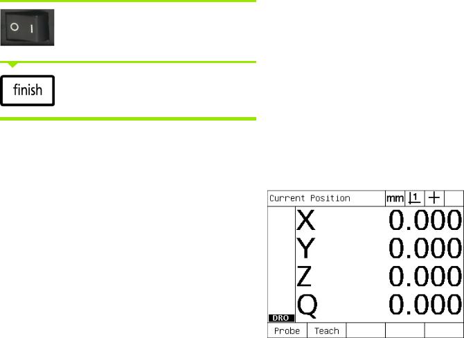
Switching on the ND 1200
Switch on the ND 1200. The POWER switch is located on the rear of the enclosure. After switching the power on, or after a power failure, the power-up screen will be displayed.
Press the FINISH key to advance from the power-up screen to the DRO.
Your ND 1200 is now ready for operation and is in the Current Position operating mode. Encoder position values will be displayed for all axes.
Power-up screen
DRO screen
16 |
1 Operation |

Establishing a repeatable machine zero
If your ND 1200 was configured to establish a machine zero upon power-up, a message will be displayed asking you to cross reference marks or enter hard-stop axis reference positions. The machine zero is used by the ND 1200 to apply error correction data as measurements are performed. To establish a repeatable machine zero you must either:
UMove the stage to have encoder reference mark crossings recognized on each axis or
Umove the stage to the hard-stop reference position and press ENTER on each axis when no encoder reference marks are present.
If the requirement to cross reference marks is bypassed by pressing the CANCEL soft key, error correction data that might be stored in your ND 1200 will not be applied.
Switching off the ND 1200
Switch the ND 1200 off. The parameter settings, error compensation tables and recorded programs that have been saved during operation will be retained in memory.
Your ND 1200 might also have been configured to retain measurement results across power cycles
1.2 Basic Functions of the ND 1200
ND 1200 QUADRA-CHEK |
17 |

1.2 Basic Functions of the ND 1200
Panel key descriptions
Descriptions of panel key functions are provided in the following pages for MEASUREMENT function, COMMAND, MODE selection, AXIS, FAST TRACK, SEND, LCD ON/OFF, and MENU keys. Soft key functions are also described later in the next section as part of screen and soft key layout descriptions.
MEASURE keys Function
Measure point: Press the POINT key once to measure one point, or twice to use auto repeat to measure a series of points. A minimum of one data point is required to measure a point.
Measure line: Press the LINE key once to
measure one line, or twice to use auto repeat
to measure a series of lines. A minimum of ND 1200 Panel keys two data points are required to measure a
line.
Measure circle: Press the CIRCLE key once to measure one circle, or twice to use auto repeat to measure a series of circles. A minimum of three data points are required to measure a circle.
Measure distance: Press the DISTANCE key once to measure one distance, or twice to use auto repeat to measure a series of distances. Two points are required to measure a distance.
Measure angle: Press the ANGLE key once to measure one angle, or twice to use auto repeat to measure a series of angles. Collect a minimum of two data points, then press the ENTER key on each leg of an angle.
Align part: Press the SKEW key to compensate electronically for non-square part alignment on the primary axis.
Use Measure Magic: Press the MEASURE MAGIC key to automatically measure any geometric feature or twice to measure a series of like features. Collect the desired points and press the FINISH key; Measure Magic analyzes the data and determines the feature type.
18 |
1 Operation |

COMMAND keys |
Function |
|
|
Enter data: Press the ENTER key to enter |
|
|
points during feature measurements or to |
|
|
enter values into configuration fields. |
|
|
Pressing the ENTER key indicates that data |
|
|
from a measurement or in a field is ready for |
|
|
use. |
|
|
|
|
|
Finish a measurement: Press the FINISH |
|
|
key to complete a feature measurement. |
|
|
Pressing the FINISH key a second time |
|
|
returns the user to the DRO screen. |
|
|
|
|
|
Delete data or features: Press the CANCEL |
|
|
key to delete the last point entered, data in |
|
|
configuration fields or any highlighted feature |
|
|
from the feature list. |
|
|
|
|
|
Quit current activity: Press the QUIT key to |
|
|
abandon the current task and return to the |
|
|
DRO screen or to exit the feature list. |
|
|
|
|
|
|
|
MODE keys |
Function |
|
|
Select unit of measure: Press the UNIT OF |
|
|
MEASURE key to toggle between |
|
|
millimeters and inches. The current unit of |
|
|
measure is displayed in the upper right corner |
|
|
of the screen. |
|
|
|
|
|
Select a datum: Press the DATUM key to |
|
|
toggle between datum 1 and datum 2.The |
|
|
current datum number is displayed in the |
|
|
upper right corner of the screen. |
|
|
|
|
|
Select a coordinate system: Press the |
|
|
COORDINATE key to toggle between |
|
|
Cartesian and polar coordinate systems. |
|
|
|
|
|
|
|
AXIS keys |
Function |
|
|
Zero an axis: Press the axis key to the right |
|
|
of the desired axis to zero the axis position |
|
|
value when establishing a zero datum. |
|
|
Preset an axis or axes: Press one or more |
|
|
axis keys to the right of the desired axis or |
|
|
axes when presetting axis position values for |
|
|
a new datum. |
|
|
|
|
1.2 Basic Functions of the ND 1200
ND 1200 QUADRA-CHEK |
19 |
1.2 Basic Functions of the ND 1200
FAST TRACK keys |
Function |
|
Left frequently used function: |
|
Press the left WIDE key to initiate |
|
the function programmed for this |
|
key. The factory default function for |
|
this key is ENTER. |
|
Right frequently used function: |
|
Press the right WIDE key to initiate |
|
the function programmed for this |
|
key. The factory default function for |
|
this key is FINISH. |
|
|
|
|
SEND key |
Function |
|
Transmit measurement results: Press the |
|
SEND key to transmit measurement data to a |
|
computer, a USB printer or a USB memory |
|
drive. |
|
|
|
|
LCD ON/OFF key |
Function |
|
Turn the LCD off or clear data: Press the |
|
LCD ON/OFF key to toggle between LCD on |
|
and LCD off, or to clear feature data, datums |
|
and part alignments (skews). |
|
|
|
|
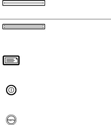
MENU key |
Function |
|
Display soft key menus: Press the MENU |
|
key to display the titles of ND 1200 menus |
|
above the soft keys. Menus include: |
|
Setup: Used by supervisors to configure |
|
the operational characteristics of the |
|
system. |
|
Prog: Used by operators and supervisors to |
|
create and recall programs of recorded |
|
measurement steps. |
|
Extra: Used by operators to conduct |
|
measurements and send measurement |
|
result data. |
|
Clear: Used by operators to clear |
|
measurement data and datums. |
|
Edge: Used by operators and supervisors |
|
to install, calibrate and select optical edge |
|
detectors. |
|
|
20 |
1 Operation |
ARROW CURSOR keys Function
Navigate menus and setup screen data fields. The up arrow cursor key is also used to begin a feature construction process.
1.2 Basic Functions of the ND 1200
ND 1200 QUADRA-CHEK |
21 |

1.2 Basic Functions of the ND 1200
LCD screen and soft key layout
ND 1200 LCD screens display information in one of four operating modes:
DRO mode displays current positions of axes
Feature evaluation mode screens can be toggled between two displays that show all measurement results and the data cloud of collected points
Feature measurement mode displays feature type, points collected and current positions of axes during measurements
Setup mode displays ND 1200 Installation and setup screens Soft keys change to support activities shown on the screens.
Installation and setup screens and soft keys are described later in Chapter 2: Installation, Setup and Specifications.
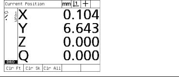
DRO mode screen and soft keys
The DRO screen shows:
Feature list of measured features on the left side
Unit of measure, current datum and probe type in the upper right corner
The current positions of all axes
Part alignment status: a small rectangle over the axis letter indicates that the part is aligned to a measurement axis (a skew was performed)
Soft key functions for selecting a probe type and teaching (calibrating) optical edge detection (optional)
DRO soft keys |
Function |
Probe |
Toggles between crosshair and optical edge |
|
detection probes |
|
|
Teach |
Initiates the optical edge detection light- |
|
calibration wizard. You will be guided through |
|
the process by messages shown on the screen |
|
|
DRO current position screen showing current axis positions
22 |
1 Operation |
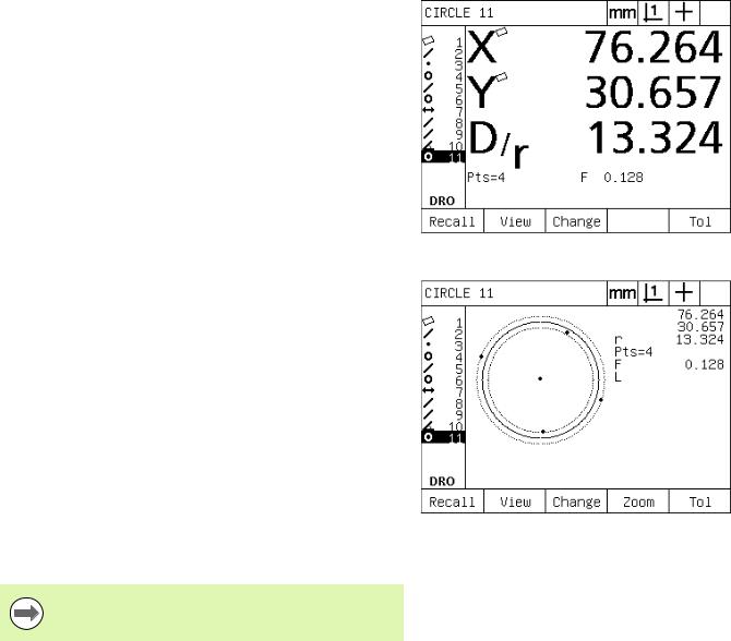
Feature evaluation mode screens and soft keys
The feature evaluation screens can be toggled between two displays by pressing the VIEW soft key to show:
Feature list of measured features on the left side
Unit of measure, current datum and probe type in the upper right corner
The feature type and number of the highlighted feature
Feature position
Geometric and dimensional values such as diameter, length or angle
Number of data points used to define the feature
Form error
Parent features used if the feature was constructed
An indication that the feature was created if applicable
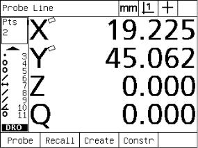
Data cloud of collected data points used to define the feature
Feature evaluation mode screen showing feature values
DRO soft keys |
Function |
|
Recall |
Displays a different feature from the feature list |
|
|
by specifying its feature number. |
|
|
|
|
View |
Toggles between the default screen showing |
|
|
axis values and the screen showing data points |
|
|
collected to define the feature. |
|
|
|
|
Change |
Shows alternative fit algorithms for the current |
|
|
feature type, such as LSBF (least squares best |
|
|
fit) and ISO. |
|
|
|
|
Zoom |
Changes magnification when viewing the data |
|
|
cloud of collected data points. |
|
|
|
Feature evaluation mode screen showing data points |
Tol |
|
|
Displays the alternative tolerances that can be |
||
|
applied to the current feature. |
|
|
|
|
Tolerances are discussed later in this chapter.
1.2 Basic Functions of the ND 1200
ND 1200 QUADRA-CHEK |
23 |
1.2 Basic Functions of the ND 1200
Feature measurement mode screen and soft keys
The feature measurement screen is displayed after initiating a feature measurement by pressing a MEASUREMENT key and shows:
Feature list of measured features on the left side
Unit of measure, current datum and probe type in the upper right corner
The feature type being probed and the number of collected data points
The current positions of all axes
DRO soft keys |
Function |
Probe |
Toggles between crosshair and optical edge |
|
detection probes (available only with optical |
|
edge detection option). |
|
|
Recall |
Recalls the first parent feature of a new feature |
|
construction. |
|
|
Create |
Displays fields for entering data to create the |
|
specified feature type. |
|
|
Const |
Initiates a new feature construction. |
|
|
Feature measurement mode screen showing feature type and points collected
24 |
1 Operation |

ND 1200 Menus
Press the MENU key to display menu titles over the soft keys at the bottom of the LCD screen. Press a menu soft key to display the corresponding menu screen. Menus include:
SETUP menu |
SETUP functions |
|
Press the SETUP menu |
|
soft key to display the |
|
collection of SETUP |
|
screens used to configure |
|
the ND 1200. Use of the |
|
setup menu is explained |
|
later in Chapter 2: |
|
Installation, Setup and |
|
Specifications. |
Access to setup menu configuration data fields is password restricted to supervisors and other technically qualified personnel. Configuration mistakes can result in serious measurement errors.
PROG menu |
PROG functions |
|
Press the PROG soft key to |
|
display the PROGRAMS |
|
screen and soft keys for |
|
program functions. Soft |
|
keys include: |
Menu titles are displayed over soft keys at the bottom of the LCD screen
1.2 Basic Functions of the ND 1200
Record |
Records a program of user |
|
key presses that can be |
|
played back later. |
|
|
Run |
Plays a program of |
|
recorded key presses. |
|
|
Edit |
Displays program steps for |
|
editing. |
|
|
Copy |
Copies a program to be |
|
edited and saved under a |
|
new name. |
|
|
Delete |
Deletes a program. |
|
|
ND 1200 QUADRA-CHEK |
25 |

1.2 Basic Functions of the ND 1200
EXTRA menu |
EXTRA functions |
|
Press the EXTRA soft key |
|
to display the EXTRA pop- |
|
up menu. The EXTRA |
|
menu is used perform |
|
many measurement and |
|
data transmission |
|
functions. Highlight a |
|
function and then press the |
|
ENTER key. EXTRA menu |
|
functions include: |
|
|
Annot |
Toggles between forward |
|
and backward annotation. |
|
|
DMS/DD |
Toggles between the |
|
display of degrees, |
|
minutes, seconds and |
|
decimal degrees. |
|
|
MCS |
Clears datums and re- |
|
establishes machine |
|
coordinates. |
|
|
MinMax |
Collects and stores |
|
minimum and maximum |
|
values until the FINISH key |
|
is pressed. |
|
|
Preset |
Sets the position of one or |
|
more axes to specified |
|
values. |
|
|
Preset! |
Recalls the last preset |
|
position. |
|
|
Prt RS |
Sends current data to the |
|
RS-232 serial port. |
|
|
Run |
Runs the last program. |
|
|
Send 2 |
Sends current X, Y data to a |
|
printer, USB drive or |
|
computer. |
|
|
Send 3 |
Sends current X, Y, Z data |
|
to a printer, USB drive or |
|
computer. |
|
|
Send 4 |
Sends current X, Y, Z, Q |
|
data to a printer, USB drive |
|
or computer. |
|
|
Send D |
Sends current diameter to |
|
a printer, USB drive or |
|
computer. |
|
|
26 |
1 Operation |
EXTRA menu |
EXTRA functions |
Send F |
Sends current form error to |
|
a printer, USB drive or |
|
computer. |
|
|
Send L |
Sends current distance to a |
|
printer, USB drive or |
|
computer. |
|
|
Send Q |
Sends current Q-axis value |
|
to a printer, USB drive or |
|
computer. |
|
|
Send R |
Sends current radius to a |
|
printer, USB drive or |
|
computer. |
|
|
Send X |
Sends current X-axis value |
|
to a printer, USB drive or |
|
computer. |
|
|
Send Y |
Sends current Y-axis value |
|
to a printer, USB drive or |
|
computer. |
|
|
Send Z |
Sends current Z-axis value |
|
to a printer, USB drive or |
|
computer. |
|
|
Send < |
Sends current angle to a |
|
printer, USB drive or |
|
computer. |
|
|
Time |
Displays the current date |
|
and time. |
|
|
Zero 2 |
Zeros X and Y axes in the |
|
current datum. |
|
|
Zero Q |
Zeros Q-axis protractor |
|
value. |
|
|
|
|
CLEAR menu |
CLEAR functions |
|
Press the clear soft key to |
|
display soft key selections |
|
for clearing data. Soft keys |
|
include: |
1.2 Basic Functions of the ND 1200
ND 1200 QUADRA-CHEK |
27 |
1.2 Basic Functions of the ND 1200
CLEAR menu |
CLEAR functions |
Clr Ft |
Clears feature data from |
|
the feature list. |
|
|
Clr Sk |
Clears the part alignment |
|
(skew). Clearing the skew |
|
does not clear any datums |
|
that have been established. |
|
|
Clr All |
Clears feature, datum and |
|
part alignment data. |
|
|
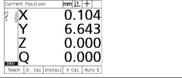
EDGE menu |
EDGE functions |
|
Press the EDGE soft key to |
|
display edge detection soft |
|
key functions. Soft keys |
|
include: |
Teach |
Calibrates edge detection |
|
for typical light to dark edge |
|
transitions. |
|
|
D. Cal |
Calibrates edge detection |
|
for fuzzy or irregular light to |
|
dark edge transitions. |
|
|
Install |
Installs edge detection. |
|
|
X Cal |
Calibrates crosshair and |
|
edge detector probes to |
|
indicate identical positions. |
|
|
Auto E |
Toggles between |
|
automatic and manual edge |
|
detection. |
|
|
28 |
1 Operation |

1.3 Preparing to Measure
Power-up the ND 1200
USwitch on the ND 1200. The POWER switch is located on the rear of the enclosure. After switching the power on, or after a power failure, the power-up screen will be displayed. See "Switching on the ND 1200" on page 16.
UPress the FINISH key to advance from the power-up screen to the DRO.
If your ND 1200 was configured to establish a machine zero upon powering up, a message will be displayed asking you to cross reference marks or specify axis references manually.
Establish machine zero
A repeatable machine zero is required if you plan to retain feature measurement results across a power cycle or if error correction will be applied to your measurements.
Often feature data retention and error correction are not desired. In these cases, it is not necessary to establish a machine zero.
To establish a repeatable machine zero:
UMove the stage to have reference mark crossings recognized on each axis or
Umove the stage to the hard-stop reference position and press ENTER on each axis when no encoder reference marks are present.
1.3 Preparing to Measure
ND 1200 QUADRA-CHEK |
29 |
1.3 Preparing to Measure
Adjust LCD screen contrast
If necessary, adjust the LCD screen contrast using the decimal point and +/- keys located on the numeric keypad.
UPress the DECIMAL POINT key to increase the contrast
UPress the +/- key to decrease the contrast
Select unit of measure
UPress the UNIT OF MEASURE key to toggle between millimeters and inches.
Select a datum
UPress the DATUM key to toggle between Datum 1 and Datum 2.
Select a coordinate system
UPress the COORDINATE key to toggle between Cartesian and polar coordinate systems.
30 |
1 Operation |
Loading...