


 Loading...
Service Manual
Data Interfaces
for HEIDENHAIN
Controls of the Series
TNC 122 |
TNC 351/355 |
TNC 124 |
TNC 360 |
TNC 125 |
TNC 370 |
TNC 131/135 |
TNC 406 |
TNC 145 |
TNC 407/415 |
TNC 150/151/155 |
TNC 410 |
TNC 246 |
TNC 425 |
TNC 2500 |
TNC 426/430 |
TNC 306 |
CNC 232B |
TNC 310 |
CNC 234.xx |
TNC 335 |
CNC 332 |
July 2011

1 How to Use this Service Manual
1.1 |
Target Group .......................................................................................................................................................... |
5 |
1.2 |
About this Manual ................................................................................................................................................. |
5 |
1.3 |
Other Documentation on Data Interfaces ........................................................................................................... |
5 |
1.4 |
Meaning of the symbols used in this manual ..................................................................................................... |
6 |
2 General Information on the Data Interfaces
2.1 RS-232-C/V.24 Interface ........................................................................................................................................ |
7 |
|
2.1.1 |
Hardware.................................................................................................................................................. |
7 |
2.1.2 |
Signal levels ............................................................................................................................................. |
7 |
2.1.3 |
HEIDENHAIN data transfer software ....................................................................................................... |
8 |
2.2 RS-422/V.11 Interface............................................................................................................................................ |
9 |
|
2.2.1 |
Hardware.................................................................................................................................................. |
9 |
2.2.2 |
Signal levels ........................................................................................................................................... |
10 |
2.2.3 |
HEIDENHAIN data transfer software ..................................................................................................... |
10 |
2.3 Ethernet |
................................................................................................................................................................ |
10 |
2.3.1 |
Hardware ................................................................................................................................................ |
11 |
2.3.2 |
Signal structure ...................................................................................................................................... |
11 |
2.3.3 ................................................................................................... |
Connecting the TNC to data networks |
12 |
3 Connector Designations and Layouts
3.1 |
Connector Designations and Layouts of TNC 125, 131, 135, 145, 150, 151/155 ............................................ |
13 |
|
3.2 |
Connector Designations and Layouts of TNC 122, TNC 2xx, TNC 3xx, TNC 4xx, CNC xxx .......................... |
14 |
|
|
3.2.1 |
RS-232-C/V.24 data interface, 25-pin, D-sub |
|
|
|
Flange socket with female insert ........................................................................................................... |
14 |
3.2.2RS-232-C/V.24 data interface, 9-pin, D-sub
Flange socket with female insert ........................................................................................................... |
15 |
3.2.3RS-422/V.11 data interface, 15-pin, D-sub
|
|
Flange socket with female insert ........................................................................................................... |
16 |
4 Wiring Diagrams of the Data Interfaces |
|
||
4.1 |
RS-232-C/V.24 Overview.................................................................................................................................... |
19 |
|
4.2 |
RS-422/V.11 Overview ........................................................................................................................................ |
20 |
|
4.3 |
Ethernet Overview............................................................................................................................................... |
20 |
|
4.4 |
RS-232-C/V.24 Diagrams..................................................................................................................................... |
20 |
|
4.5 |
RS-422/V.11 Diagram .......................................................................................................................................... |
33 |
|
4.6 |
V.11 -> V.24 Converter......................................................................................................................................... |
33 |
|
5 Operating Modes of the Data Interfaces |
|
||
5.1 |
Operating Modes on TNC 125, 131, 135, 145, 150, 151/155............................................................................. |
35 |
|
5.2 |
Operating Modes on TNC 122 to TNC 430 ........................................................................................................ |
36 |
|
6 Machine Parameters for the Data Interfaces |
|
||
6.1 |
Machine Parameters for TNC 125, 131, 135, 145, 150, 151/155, 351/355 ....................................................... |
39 |
|
|
6.1.1 |
Overview................................................................................................................................................ |
39 |
|
6.1.2 Description of the machine parameters................................................................................................. |
40 |
|
6.2 |
Machine Parameters for for TNC 122/124 ......................................................................................................... |
48 |
|
|
6.2.1 |
Overview................................................................................................................................................ |
48 |
|
6.2.2 Description of the machine parameters................................................................................................. |
48 |
|
Juni 2011

6.3 |
Machine Parameters for TNC 232/246............................................................................................................... |
49 |
|
|
6.3.1 |
Overview................................................................................................................................................ |
49 |
|
6.3.2 |
Description of the machine parameters................................................................................................. |
50 |
6.4 |
Machine Parameters for TNC 306/335/360/2500/CNC 234/TNC 370 ............................................................. |
51 |
|
|
6.4.1 |
Overview................................................................................................................................................ |
51 |
|
6.4.2 |
Description of the machine parameters................................................................................................. |
52 |
6.5 |
Machine Parameters for TNC 310/410............................................................................................................... |
54 |
|
|
6.5.1 |
Overview................................................................................................................................................ |
54 |
|
6.5.2 |
Description of the machine parameters................................................................................................. |
55 |
6.6 |
Machine Parameters for TNC 406/407/415/425................................................................................................ |
56 |
|
|
6.6.1 |
Overview................................................................................................................................................ |
56 |
|
6.6.2 |
Description of the machine parameters of TNC 406/407/415 .............................................................. |
57 |
|
6.6.3 |
Description of the machine parameters of TNC 415 B/425 ................................................................... |
60 |
6.7 |
Machine Parameters for TNC 426/430............................................................................................................... |
63 |
|
|
6.7.1 |
Overview................................................................................................................................................ |
63 |
|
6.7.2 |
Description of the machine parameters................................................................................................. |
64 |
7 |
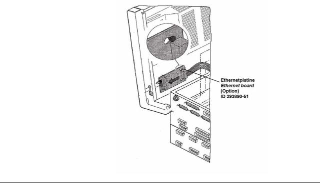
Ethernet Card (Option) in TNC 426/430 Controls |
|
7.1 |
Installing the Ethernet Card................................................................................................................................ |
65 |
7.2 |
Connecting the Ethernet Hardware ................................................................................................................... |
66 |
7.3 |
Ethernet Configuration in the TNC .................................................................................................................... |
68 |
|
7.3.1 Settings in DEFINE NET......................................................................................................................... |
68 |
|
7.3.2 Settings in DEFINE MOUNT .................................................................................................................. |
72 |
7.4 |
Checking the Connection to the Server............................................................................................................. |
79 |
7.5 |
Finding the Hardware Address of the Ethernet Card ....................................................................................... |
80 |
7.6 |
Working with the Ethernet Interface ................................................................................................................. |
81 |
|
7.6.1 Establish network connection (mount) .................................................................................................. |
81 |
|
7.6.2 Unmounting a network connection........................................................................................................ |
83 |
8 Error Messages and their Causes
8.1 |
Error Messages Related to the RS-232C and RS-422 Interfaces...................................................................... |
85 |
|
|
8.1.1 |
Error messages at the TNC in the ME mode......................................................................................... |
85 |
|
8.1.2 |
Error messages at the ME ..................................................................................................................... |
86 |
|
8.1.3 |
Error messages at the FE in the ME mode............................................................................................ |
87 |
|
8.1.4 |
Error messages at the TNC in the FE mode .......................................................................................... |
89 |
|
8.1.5 |
Error messages during data transfer...................................................................................................... |
90 |
8.2 |
Ethernet Error Messages..................................................................................................................................... |
91 |
|
9 |
Tables |
|
9.1 |
7-Bit ASCII Code................................................................................................................................................... |
93 |
9.2 |
Powers of 2........................................................................................................................................................... |
97 |
HEIDENHAIN Service-Handbuch Datenschnittstellen

1 How to Use this Service Manual
1.1Target Group
This Service Manual has been written for specialist electricians for service, maintenance and commissioning as well as for end users of machine tools with HEIDENHAIN controls.
1.2About this Manual
This manual provides support for connecting, machine parameter setting and troubleshooting the data interfaces RS-232-C, RS-422 and Ethernet of the following HEIDENHAIN controls.
TNC 122
TNC 124
TNC 125
TNC 131/135
TNC 145
TNC 150/151/155
TNC 246
TNC 2500
TNC 306
TNC 310
TNC 335
TNC 351/355
TNC 360
TNC 370
TNC 406
TNC 407/415
TNC 410
TNC 425
TNC 426/430
CNC 232B
CNC 234.xx
CNC 332
1.3Other Documentation on Data Interfaces
For information on the data interfaces of the HEIDENHAIN controls as of iTNC 530, TNC 320, TNC 620, etc., please refer to the respective Technical Manual, User's Manual and Service Manual.
June 2011 |
1 – 5 |

1.4Meaning of the symbols used in this manual
DANGER
Failure to comply with this information could result in most serious or fatal injuries, and/or in substantial material damage.
Attention
Failure to comply with this information could result in injuries and interruptions of operation, including material damage.
Note
These boxes contain important and useful information.
1 – 6 |
HEIDENHAIN Service Manual for Data Interfaces |
2 General Information on the Data Interfaces
2.1 RS-232-C/V.24 Interface
RS-232-C is the designation of a serial interface for transfer rates of up to 19,200 bps based on the American EIA standard of the same name. Data transfer is executed asynchronously, with a start bit before each character and one or two stop bits after each character.
The interface is designed for transmission distances of up to 30 meters.
The RS-232-C interface has been adopted with slight modifications and introduced into Europe as the V.24 interface. The relevant German standard is DIN 66020.
2.1.1 Hardware
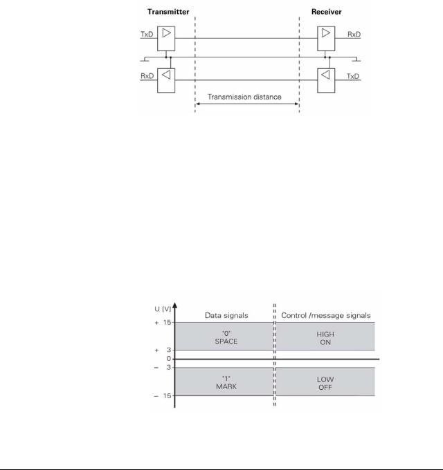
The physical connection between two RS-232-C/V.24 interfaces is an asymmetrical line, i.e. the common ground connection between transmitter and receiver is used as a return wire.
Physical connections:
2.1.2 Signal levels
With the RS-232-C/V.24 interface one must differentiate between two different signal lines and their levels.
Data lines:
The data signals are defined as being logical one (MARK) over the range –3 V to +15 V and logical zero (SPACE) over the range +3 V to +15 V.
Control and signal lines:
These signals are defined as being ON (High) over the range +3 V to +15 V and as OFF (Low) over the range –3 V to –15 V.
For all of the signals, the voltage range from –3 V to +3 V is not defined as a logic level and can therefore not be evaluated.
June 2011 |
2 – 7 |
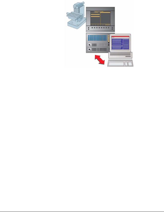
2.1.3 HEIDENHAIN data transfer software
TNCremoNT is a software package for communication between PCs and HEIDENHAIN controls or programming stations.
Data transfer is carried out over the Ethernet network or the serial interface.
TNCremoNT can be run on all common personal computers.
A version of Windows 2000, XP, Vista or 7 must be used as operating system.
Windows 2000, Windows XP, Windows Vista and Windows 7 are registered trademarks of the Microsoft Corporation.
Functions of
TNCremoNT
The TNCremoNT software package includes:
TNCremoNT
Convenient data transfer and management functions that are operated from the PC
Screendump of the control’s screen
Read-out of the control’s log
Pallet management for creating, editing and transmitting pallet tables
Creating a service file
TNCserver
Transfer via the serial interface with operation on the control for all HEIDENHAIN controls and many HEIDENHAIN position displays.
Support of all HEIDENHAIN protocols including simple data input/output.
TNCbackup
Features for data backup and restoration
TNCcmd
Command line tool for all transfer functions
TNClog
Log viewer to view and filter the control's log file
TNCremoPlus (available for a fee)
View control screen (live screen)
The selection of features you can use in TNCremoNT depends on your control. Refer to the overview of features for more detailed information.
2 – 8 |
HEIDENHAIN Service Manual for Data Interfaces |
2.2 RS-422/V.11 Interface
As the features of the V.24/RS-232-C interface are limited, the V.11/RS-422 interface was developed. This interface is also standardized, but operates symmetrically.
The RS-422/V.11 serial interface is suitable for data transfer rates up to 10 Mbps. At a baud rate of 38,400 bauds, data can be transferred over 1 km cable.
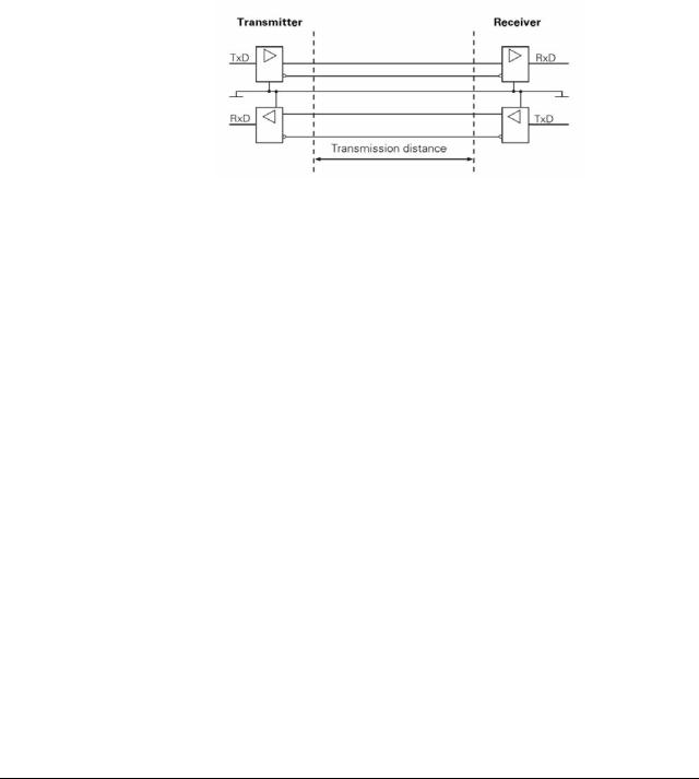
2.2.1 Hardware
The V.11/RS-422 standard operates with differential voltages. This offers the advantage that interferences act on both signal lines equally and simultaneously over the transmission distance. As the receiver only evaluates the differential voltages of the two signal lines, interferences are not relevant. By this means, considerably longer lines can be installed, and the transfer rate is much higher, as interferences are limited.
Physical connections:
June 2011 |
2 – 9 |

2.2.2 Signal levels
With the V.11/RS-422 interface the signals are both transmitted and received as differential voltage.
A positive differential voltage means a logical zero (OFF), a negative differential voltage means a logical one (ON).
Differential voltages between
Udmin = 2 V and Udmax = 5 V are output; the control detects the differential voltages
between
Udmin = 0.2 V and Udmax = 6 V as logically defined levels.
2.2.3 HEIDENHAIN data transfer software
See chapter 2.1.3
2.3 Ethernet
Ethernet technology is most frequently used in local networks. It was developed by Digital Equipment, Intel and Xerox in 1982. Ethernet operates at a data transfer rate of up to 100 Mbps (Fast Ethernet); the hardware versions most frequently used - such as 10Base2 (Thin Ethernet, Cheapernet), 10Base5 (Thick Ethernet, Yellow Cable) or 10BaseT (Twisted Pair) - operate at 10 Mbps. They differ in price, routing complexity or network topology, but not in the method of accessing media.
The data transfer rate strongly depends on the amount of traffic at the time on the net.
Realistic values: |
NC program up to 200 Kbps |
|
ASCII file up to 1 Mbps |
2 – 10 |
HEIDENHAIN Service Manual for Data Interfaces |
2.3.1 Hardware
The integrated Ethernet expansion card provides you with both the 10Base2 (BNC) port and the 10BaseT (twisted pair). You can only use one of the two connections at one time. Both connections are electrically isolated from the control electronics.
Connection and wiring diagrams see chapter 7.2, pin layouts see chapter 3.2.
X26 Ethernet interface, BNC connection (coaxial cable, 10Base2)
The 10Base2 connection is also commonly known as ThinEthernet or CheaperNet.
You connect the TNC with your network via BNC-T connector. The maximum cable length is 185 m (coaxial cable). The network topology is a linear bus. The "open" ends of the bus must be terminated with terminating resistors.
X25 Ethernet interface, RJ45 connection (10BaseT)
The twisted-pair cable of the 10BaseT connector may be either shielded or non-shielded.
Maximum cable length: |
non-shielded: |
100 m |
|
shielded: |
400 m |
The network topology is a star connection. This means a central node establishes the connection to the other participants.
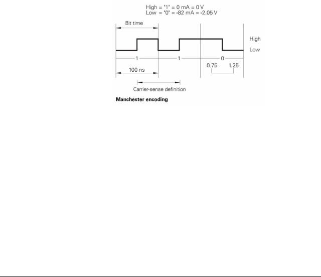
2.3.2 Signal structure
Ethernet frames are transferred in Manchester code which is a self-clocking code. The synchronization or the transfer of a transmit clock pulse is executed such that each bit is transmitted inverted in the first half of the transfer period, i.e. the bit rate is half the baud rate. A data rate of 10 Mbps results in a bit time of 100 ns. Carrier detect (activity on the cable) is indicated by the presence of signal level changes. If the signal level does not change in a bit time interval between 0.75 and 1.25 after the last transition, no carrier is detected (see figure).
The network settings of the TNC are described in the Technical Manual and in chapter 7 (Ethernet) of this Service Manual.
June 2011 |
2 – 11 |
2.3.3 Connecting the TNC to data networks
The HEIDENHAIN control models TNC 426/TNC 430 can optionally1) be equipped with an Ethernet data interface. Via this interface, TNC 426/TNC 430 can be integrated into data networks as client.
The TNC transfers data using the TCP/IP protocol (Transmission Control Protocol / Internet Protocol) and with the aid of the NFS, version 2 (Network File System). Since TCP/IP and NFS have been implemented in UNIX systems in the first place, you can usually connect the TNC in the UNIX world without any additional software.
The PC world with Microsoft operating systems, however, also works with TCP/IP, but not with NFS. For this reason, additional software is usually required for PC networks. HEIDENHAIN recommends the following network software:
Operating system |
Network Software |
|
|
WIN 2000 |
CIMCO NFS |
WIN XP |
available from HEIDENHAIN under ID 339737-xx |
WIN Vista |
|
WIN 7 |
|
|
|
Note |
|
In principle, other NFS servers can be used as well.
However, due to the great variety of software providers, HEIDENHAIN is not a in position to provide technical support in adapting other NFS servers.
1)Control models that can be operated with the Ethernet card: see chapter 2. The network settings of the TNC are described in the Technical Manual and in chapter 7 (Ethernet) of this Service Manual.
2 – 12 |
HEIDENHAIN Service Manual for Data Interfaces |

3 Connector Designations and Layouts
3.1 Connector Designations and Layouts of TNC 125, 131, 135, 145, 150, 151/155
RS-232-C/V.24 data interface, 14-pin, Amphenol
Flange socket with female insert
|
Pin no. |
Assignment |
Designation |
|
|
|
|
|
1 |
GND |
Chassis ground |
|
|
|
|
|
2 |
Not assigned |
|
|
|
|
|
|
3 |
Not assigned |
|
|
|
|
|
|
4 |
Not assigned |
|
|
|
|
|
|
5 |
RTS |
Request to Send |
|
|
|
|
|
6 |
DSR |
Data Set Ready |
|
|
|
|
|
7 |
Not assigned |
|
|
|
|
|
|
8 |
Not assigned |
|
|
|
|
|
|
9 |
Not assigned |
|
|
|
|
|
|
10 |
Not assigned |
|
|
|
|
|
|
11 |
DTR |
Data Terminal Ready |
|
|
|
|
|
12 |
TxD |
Transmit Data |
|
|
|
|
|
13 |
CTS |
Clear to Send |
|
|
|
|
|
14 |
RXD |
Receive Data |
|
|
|
|
|
Chassis |
Ext. shield |
|
|
|
|
|
June 2011 |
3 – 13 |

3.2 Connector Designations and Layouts of TNC 122, TNC 2xx, TNC 3xx, TNC 4xx, CNC xxx
3.2.1RS-232-C/V.24 data interface, 25-pin, D-sub
Flange socket with female insert
Pin no. |
Assignment |
Designation |
|
|
|
1 |
Shield |
Chassis Ground |
|
|
|
2 |
RxD |
Receive Data |
|
|
|
3 |
TxD |
Transmit Data |
|
|
|
4 |
CTS |
Clear to Send |
|
|
|
5 |
RTS |
Request to Send |
|
|
|
6 |
DTR |
Data Terminal Ready |
|
|
|
7 |
GND (0 V *2) |
Signal Ground |
|
|
|
8 to 19 |
Not assigned |
|
|
|
|
20 |
DSR |
Data Set Ready |
|
|
|
21 to 25 |
Not assigned |
|
|
|
|
Chassis |
External shield = Chassis |
|
|
|
|
Control model |
RS-232-C/V.24 connector |
|
|
||
|
|
|
|
|
|
|
X21 |
X25 |
|
X6 |
X26 |
|
|
|
|
|
|
TNC 122 |
x |
|
|
|
|
|
|
|
|
|
|
TNC 246 |
|
|
|
x |
|
|
|
|
|
|
|
TNC 2500/B/C |
|
x |
|
|
|
|
|
|
|
|
|
TNC 306 |
|
x |
|
|
|
|
|
|
|
|
|
TNC 335 |
|
x |
|
|
|
|
|
|
|
|
|
TNC 351/355 |
|
|
|
|
x |
|
|
|
|
|
|
TNC 360 |
|
x |
|
|
|
|
|
|
|
|
|
TNC 406 |
x |
|
|
|
|
|
|
|
|
|
|
TNC 407 |
x |
|
|
|
|
|
|
|
|
|
|
TNC 410 |
x |
|
|
|
|
|
|
|
|
|
|
TNC 415/B |
x |
|
|
|
|
|
|
|
|
|
|
TNC 425 |
x |
|
|
|
|
|
|
|
|
|
|
TNC 426 |
x |
|
|
|
|
|
|
|
|
|
|
TNC 430 |
x |
|
|
|
|
|
|
|
|
|
|
CNC 232B |
|
|
|
x |
|
|
|
|
|
|
|
CNC 234.xxx |
|
x |
|
|
|
|
|
|
|
|
|
CNC 332 |
|
|
|
|
x |
|
|
|
|
|
|
3 – 14 |
HEIDENHAIN Service Manual for Data Interfaces |

3.2.2RS-232-C/V.24 data interface, 9-pin, D-sub
Flange socket with female insert
Pin no. |
Assignment |
Designation |
|
|
|
1 |
Shield |
Chassis Ground |
|
|
|
2 |
TxD |
Transmit Data |
|
|
|
3 |
RxD |
Receive Data |
|
|
|
4 |
DSR |
Data Set Ready |
|
|
|
5 |
GND |
Signal Ground |
|
|
|
6 |
DTR |
Data Terminal Ready |
|
|
|
7 |
CTS |
Clear to Send |
|
|
|
8 |
RTS |
Request to Send |
|
|
|
9 |
Not assigned |
|
|
|
|
Chassis |
External shield = Chassis |
|
|
|
|
Control model |
RS-232-C/V.24 connector |
|||
|
|
|
|
|
|
X21 |
|
|
|
|
|
|
|
|
TNC 124 |
x |
|
|
|
|
|
|
|
|
TNC 310 |
x |
|
|
|
|
|
|
|
|
TNC 370 |
x |
|
|
|
|
|
|
|
|
June 2011 |
3 – 15 |

3.2.3RS-422/V.11 data interface, 15-pin, D-sub
Flange socket with female insert
Pin no. |
Assignment |
Designation |
|
|
|
1 |
Shield |
Chassis Ground |
|
|
|
2 |
RxD |
Receive Data |
|
|
|
3 |
CTS |
Clear to Send |
|
|
|
4 |
TxD |
Transmit Data |
|
|
|
5 |
RTS |
Request to Send |
|
|
|
6 |
DSR |
Data Set Ready |
|
|
|
7 |
DTR |
Data Terminal Ready |
|
|
|
8 |
GND |
Signal Ground |
|
|
|
9 |
RxD |
Receive Data |
|
|
|
10 |
CTS |
Clear to Send |
|
|
|
11 |
TxD |
Transmit Data |
|
|
|
12 |
RTS |
Request to Send |
|
|
|
13 |
DSR |
Data Set Ready |
|
|
|
14 |
DTR |
Data Terminal Ready |
|
|
|
15 |
Do not assign |
|
|
|
|
Control model |
RS-422/V.11 connector |
|||
|
|
|
|
|
|
X22 |
|
|
|
|
|
|
|
|
TNC 406 |
x |
|
|
|
|
|
|
|
|
TNC 407 |
x |
|
|
|
|
|
|
|
|
TNC 415/B |
x |
|
|
|
|
|
|
|
|
TNC 425 |
x |
|
|
|
|
|
|
|
|
TNC 426 |
x |
|
|
|
|
|
|
|
|
TNC 430 |
x |
|
|
|
|
|
|
|
|
3 – 16 |
HEIDENHAIN Service Manual for Data Interfaces |
X25 Ethernet interface, RJ45 connection, 10BaseT
Maximum cable length: non-shielded: 100 m shielded: 400 m
RJ45 connection (female) 8-pin |
Assignment |
|
|
1 |
TX+ |
|
|
2 |
TX– |
|
|
3 |
REC+ |
|
|
4 |
Not assigned |
|
|
5 |
Not assigned |
|
|
6 |
REC– |
|
|
7 |
Not assigned |
|
|
8 |
Not assigned |
|
|
X26 Ethernet interface, BNC connection, 10Base2 (coaxial cable)
Maximum cable length: 180 m
BNC connection (female) |
Assignment |
|
|
|
|
|
|
Inner conductor (core) |
Data (RXI, TXD) |
|
|
|
|
|
|
Shield |
GND |
|
|
|
|
|
|
|
|
|
|
Control model |
Ethernet connector |
|
|
|
(option) |
|
|
|
|
|
|
|
X25 |
X26 |
|
|
|
|
|
TNC 426.B |
x |
x |
|
|
|
|
|
TNC 430.A |
x |
x |
|
|
|
|
|
TNC 426M/430M |
x |
x |
|
|
|
|
|
June 2011 |
3 – 17 |

3 – 18 |
HEIDENHAIN Service Manual for Data Interfaces |

4 Wiring Diagrams of the Data Interfaces
4.1 RS-232-C/V.24 Overview
|
Connection of peripheral, 25-pin |
|
Connection of peripheral, 9-pin |
||||||||
|
Wiring diagram for connection |
|
Wiring diagram for connection |
||||||||
|
|
|
via adapter and |
|
|
|
via adapter and |
||||
|
direct |
|
JH cable |
|
|
direct |
|
JH cable |
|
||
Control |
HW |
SW |
HW |
|
SW |
|
HW |
SW |
HW |
|
SW |
TNC 122 |
11 |
12 |
2 |
|
1 |
|
10 |
10 |
3 |
|
4 |
|
|
|
|
|
|
|
|
|
|
|
|
TNC 124 |
- |
- |
14 |
|
14 |
|
- |
- |
15 |
|
15 |
|
|
|
|
|
|
|
|
|
|
|
|
TNC 125 |
13 |
13 |
7 |
|
8 |
|
9 |
9 |
5 |
|
6 |
|
|
|
|
|
|
|
|
|
|
|
|
TNC 131 |
13 |
13 |
7 |
|
8 |
|
9 |
9 |
5 |
|
6 |
|
|
|
|
|
|
|
|
|
|
|
|
TNC 135 |
13 |
13 |
7 |
|
8 |
|
9 |
9 |
5 |
|
6 |
|
|
|
|
|
|
|
|
|
|
|
|
TNC 145 |
13 |
13 |
7 |
|
8 |
|
9 |
9 |
5 |
|
6 |
|
|
|
|
|
|
|
|
|
|
|
|
TNC 150 |
13 |
13 |
7 |
|
8 |
|
9 |
9 |
5 |
|
6 |
|
|
|
|
|
|
|
|
|
|
|
|
TNC 151/155 |
13 |
13 |
7 |
|
8 |
|
9 |
9 |
5 |
|
6 |
|
|
|
|
|
|
|
|
|
|
|
|
TNC 246 |
11 |
12 |
2 |
|
1 |
|
10 |
10 |
3 |
|
4 |
|
|
|
|
|
|
|
|
|
|
|
|
TNC 2500/B/C |
11 |
12 |
2 |
|
1 |
|
10 |
10 |
3 |
|
4 |
|
|
|
|
|
|
|
|
|
|
|
|
TNC 306 |
11 |
12 |
2 |
|
1 |
|
10 |
10 |
3 |
|
4 |
|
|
|
|
|
|
|
|
|
|
|
|
TNC 310 |
- |
- |
14 |
|
14 |
|
- |
- |
15 |
|
15 |
|
|
|
|
|
|
|
|
|
|
|
|
TNC 335 |
11 |
12 |
2 |
|
1 |
|
10 |
10 |
3 |
|
4 |
|
|
|
|
|
|
|
|
|
|
|
|
TNC 351/355 |
11 |
12 |
2 |
|
1 |
|
10 |
10 |
3 |
|
4 |
|
|
|
|
|
|
|
|
|
|
|
|
TNC 360 |
11 |
12 |
2 |
|
1 |
|
10 |
10 |
3 |
|
4 |
|
|
|
|
|
|
|
|
|
|
|
|
TNC 370 |
- |
- |
14 |
|
14 |
|
10 |
10 |
15 |
|
15 |
|
|
|
|
|
|
|
|
|
|
|
|
TNC 406 |
11 |
12 |
2 |
|
1 |
|
10 |
10 |
3 |
|
4 |
|
|
|
|
|
|
|
|
|
|
|
|
TNC 407 |
11 |
12 |
2 |
|
1 |
|
10 |
10 |
3 |
|
4 |
|
|
|
|
|
|
|
|
|
|
|
|
TNC 410 |
11 |
12 |
2 |
|
1 |
|
10 |
10 |
3 |
|
4 |
|
|
|
|
|
|
|
|
|
|
|
|
TNC 415/B |
11 |
12 |
2 |
|
1 |
|
10 |
10 |
3 |
|
4 |
|
|
|
|
|
|
|
|
|
|
|
|
TNC 425 |
11 |
12 |
2 |
|
1 |
|
10 |
10 |
3 |
|
4 |
|
|
|
|
|
|
|
|
|
|
|
|
TNC 426 |
11 |
12 |
2 |
|
1 |
|
10 |
10 |
3 |
|
4 |
|
|
|
|
|
|
|
|
|
|
|
|
TNC 430 |
11 |
12 |
2 |
|
1 |
|
10 |
10 |
3 |
|
4 |
|
|
|
|
|
|
|
|
|
|
|
|
CNC 232B |
11 |
12 |
2 |
|
1 |
|
10 |
10 |
3 |
|
4 |
|
|
|
|
|
|
|
|
|
|
|
|
CNC 234.XXX |
11 |
12 |
2 |
|
1 |
|
10 |
10 |
3 |
|
4 |
|
|
|
|
|
|
|
|
|
|
|
|
CNC 332 |
11 |
12 |
2 |
|
1 |
|
10 |
10 |
3 |
|
4 |
|
|
|
|
|
|
|
|
|
|
|
|
HW: Wiring diagram for data transfer with hardware handshake
SW: Wiring diagram for data transfer with software handshake
June 2011 |
4 – 19 |
4.2 RS-422/V.11 Overview
|
Control model |
Connection diagram |
|
|
|
|
TNC 406 |
16 |
|
|
|
|
TNC 407 |
16 |
|
|
|
|
TNC 415/B |
16 |
|
|
|
|
TNC 425 |
16 |
|
|
|
|
TNC 426 |
16 |
|
|
|
|
TNC 430 |
16 |
|
|
|
|
V.11 -> V.24 converter |
17 |
|
|
|
4.3 Ethernet Overview |
|
|
Control model |
Connection diagram |
|
|
TNC 426 |
Chapter 7.2 |
|
|
TNC 430 |
Chapter 7.2 |
|
|
4.4 RS-232-C/V.24 Diagrams
Diagram no. 1
RS-232-C/V.24 with adapter block for software handshake,
TNC 25-pin / peripheral 25-pin
Note
This wiring only allows transfer stop with DC3 (software handshake).
4 – 20 |
HEIDENHAIN Service Manual for Data Interfaces |
The RS-232-C-/V.24 data interface has different pin layouts at the logic unit and the V.24 adapter block.
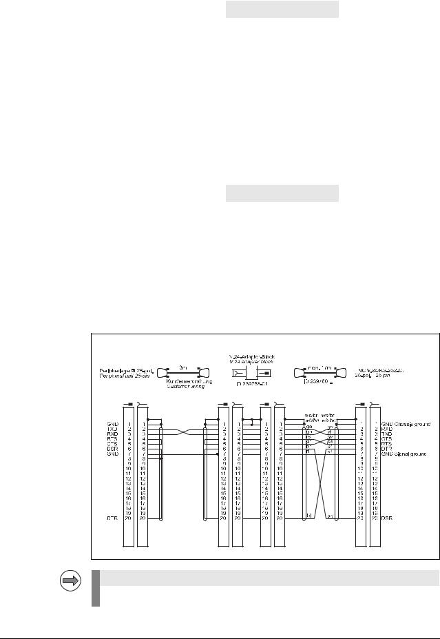
Diagram no. 2
RS-232-C/V.24 with adapter block for hardware handshake,
TNC 25-pin / peripheral 25-pin
Note |
If the pin layout of your peripheral unit differs from the above layout, the HEIDENHAIN connecting cable cannot be used.
June 2011 |
4 – 21 |
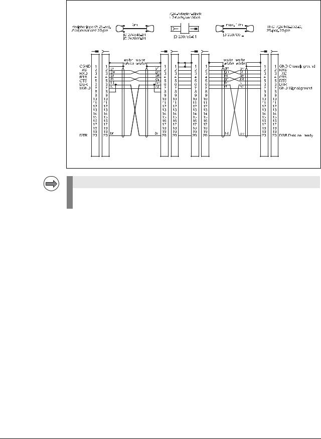
Diagram no. 3
RS-232-C/V.24 with adapter block for hardware handshake,
TNC 25-pin / peripheral 9-pin
1) Customer wiring or part available on market
4 – 22 |
HEIDENHAIN Service Manual for Data Interfaces |

Diagram no. 4
RS-232-C/V.24 with adapter block for software handshake,
TNC 25-pin / peripheral 9-pin
1) Customer wiring or part available on market
June 2011 |
4 – 23 |
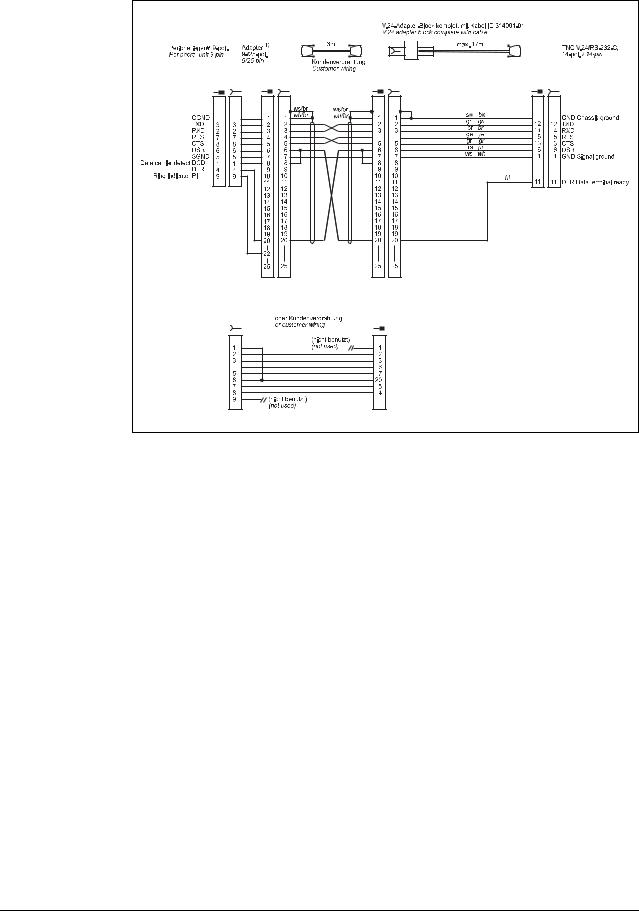
Diagram no. 5
RS-232-C/V.24 with adapter block for software handshake,
TNC 25-pin / peripheral 9-pin
1) Customer wiring or part available on market
4 – 24 |
HEIDENHAIN Service Manual for Data Interfaces |

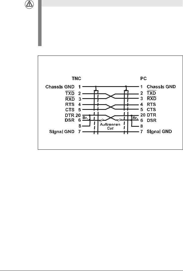
Attention
This modification applies for hardware handshake with TNC 145 to TNC 155. In these control models, the RTS pin is not connected but tied high internally.
The following modification is required for hardware handshake:
Cut the line on both sides between DRS and DTR and short-circuit DSR with DTR (at the PC: pin 6 with pin 20).
Without this modification, data transfer using hardware handshake is not only stopped but aborted immediately (like "power off).
Do not use this configuration for TNC 335 with new hardware.
June 2011 |
4 – 25 |

Diagram no. 6
RS-232-C/V.24 with adapter block for software handshake,
TNC 14-pin / peripheral 9-pin
1) Customer wiring or part available on market
4 – 26 |
HEIDENHAIN Service Manual for Data Interfaces |
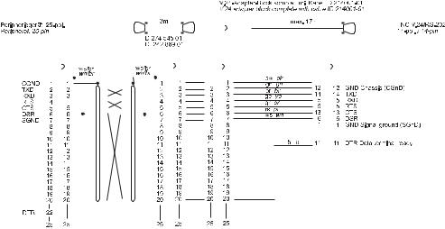
Diagram no. 7
RS-232-C/V.24 with adapter block for hardware handshake,
TNC 14-pin / peripheral 25-pin
|
|
|
|
|
|
|
|
|
|
|
|
|
|
|
|
|
|
|
|
|
|
|
|
|
|
|
|
|
|
|
|
|
|
|
|
|
|
|
|
|
|
|
|
|
|
|
|
|
|
|
|
|
|
|
|
|
|
|
|
|
|
|
|
|
|
|
|
|
|
|
|
|
|
|
|
|
|
|
|
|
|
|
|
|
|
|
|
|
|
|
|
|
|
|
|
|
|
|
|
|
|
|
|
|
|
|
|
|
|
|
|
|
|
|
|
|
|
|
|
|
|
|
|
|
|
|
|
|
|
|
|
|
|
|
|
|
|
|
|
|
|
|
|
|
|
|
|
|
|
|
|
|
|
|
|
|
|
|
|
|
|
|
|
|
|
|
|
|
|
|
|
|
|
|
|
|
|
|
|
|
|
|
|
|
|
|
|
|
|
|
|
|
|
|
|
|
|
|
|
|
|
|
|
|
|
|
|
|
|
|
|
|
|
|
|
|
|
|
|
|
|
|
|
|
|
|
|
|
|
|
|
|
|
|
|
|
|
|
|
|
|
|
|
|
|
|
|
|
|
|
|
|
|
|
|
|
|
|
|
|
|
|
|
|
|
|
|
|
|
|
|
|
|
|
|
|
|
|
|
|
|
|
|
|
|
|
|
|
|
|
|
|
|
|
|
|
|
|
|
|
|
|
|
|
|
|
|
|
|
|
|
|
|
|
|
|
|
|
|
|
|
|
|
|
|
|
|
|
|
|
|
|
|
|
|
|
|
|
|
|
|
|
|
|
|
|
|
|
|
|
|
|
|
|
|
|
|
|
|
|
|
|
|
|
|
|
|
|
|
|
|
|
|
|
|
|
|
|
|
|
|
|
|
|
|
|
|
|
|
|
|
|
|
|
|
|
|
|
|
|
|
|
|
|
|
|
|
|
|
|
|
|
|
|
|
|
|
|
|
|
|
|
|
|
|
|
|
|
|
|
|
|
|
|
|
|
|
|
|
|
|
|
|
|
|
|
|
|
|
|
|
|
|
|
|
|
|
|
|
|
|
|
|
|
|
|
|
|
|
|
|
|
|
|
|
|
|
|
|
|
|
|
|
|
|
|
|
|
|
|
|
|
|
|
|
|
|
|
|
|
|
|
|
|
|
|
|
|
|
|
|
|
|
|
|
|
|
|
|
|
|
|
|
|
|
|
|
|
|
|
|
|
|
|
|
|
|
|
|
|
|
|
|
|
|
|
|
|
|
|
|
|
|
|
|
|
|
|
|
|
|
|
|
|
|
|
|
|
|
|
|
|
|
|
|
|
|
|
|
|
|
|
|
|
|
|
|
|
|
|
|
|
|
|
|
|
|
|
|
|
|
|
|
|
|
|
|
|
|
|
|
|
|
|
|
|
|
|
|
|
|
|
|
|
|
|
|
|
|
|
|
|
|
|
|
|
|
|
|
|
|
|
|
|
|
|
|
|
|
|
|
|
|
|
|
|
|
|
|
|
|
|
|
|
|
|
|
|
|
|
|
|
|
|
|
|
|
|
|
|
|
|
|
|
|
|
|
|
|
|
|
|
|
|
|
|
|
|
|
|
|
|
|
|
|
|
|
|
|
|
|
|
|
|
|
|
|
|
|
|
|
|
|
|
|
|
|
|
|
|
|
|
|
|
|
|
|
|
|
|
|
|
|
|
|
|
|
|
|
|
|
|
|
|
|
|
|
|
|
|
|
|
|
|
|
|
|
|
|
|
|
|
|
|
|
|
|
|
|
|
|
|
|
|
|
|
|
|
|
|
|
|
|
|
|
|
|
|
|
|
|
|
|
|
|
|
|
|
|
|
|
|
|
|
|
|
|
|
|
|
|
|
|
|
|
|
|
|
|
|
|
|
|
|
|
|
|
|
|
|
|
|
|
|
|
|
|
|
|
|
|
|
|
|
|
|
|
|
|
|
|
|
|
|
|
|
|
|
|
|
|
|
|
|
|
|
|
|
|
|
|
|
|
|
|
|
|
|
|
|
|
|
|
|
|
|
|
|
|
|
|
|
|
|
|
|
|
|
|
|
|
|
|
|
|
|
|
|
|
|
|
|
|
|
|
|
|
|
|
|
|
|
|
|
|
|
|
|
|
|
|
|
|
|
|
|
|
|
|
|
|
|
|
|
|
|
|
|
|
|
|
|
|
|
|
|
|
|
|
|
|
|
|
|
|
|
|
|
|
|
|
|
|
|
|
|
|
|
|
|
|
|
|
|
|
|
|
|
|
|
|
|
|
|
|
|
|
|
|
|
|
|
|
|
|
|
|
|
|
|
|
|
|
|
|
|
|
|
|
|
|
|
|
|
|
|
|
|
|
|
|
|
|
|
|
|
|
|
|
|
|
|
|
|
|
|
|
|
|
|
|
|
|
|
|
|
|
|
|
|
|
|
|
|
|
|
|
|
|
|
|
|
|
|
|
|
|
|
|
|
|
|
|
|
|
|
|
|
|
|
|
|
|
|
|
|
|
|
|
|
|
|
|
|
|
|
|
|
|
|
|
|
|
|
|
|
|
|
|
|
|
|
|
|
|
|
|
|
|
|
|
|
|
|
|
|
|
|
|
|
|
|
|
|
|
|
|
|
|
|
|
|
|
|
|
|
|
|
|
|
|
|
|
|
|
June 2011 |
|
|
|
|
|
|
|
|
|
|
|
|
|
|
|
|
|
|
|
|
|
4 – 27 |
||||||||||||||||||||||||||
Attention
This modification applies for hardware handshake with TNC 145 to TNC 155. In these control models, the RTS pin is not connected but tied high internally.
The following modification is required for hardware handshake:
Cut the line on both sides between DRS and DTR and short-circuit DSR with DTR (at the PC: pin 6 with pin 20).
Without this modification, data transfer using hardware handshake is not only stopped but aborted immediately (like "power off).
Do not use this configuration for TNC 335 with new hardware.
4 – 28 |
HEIDENHAIN Service Manual for Data Interfaces |

Diagram no. 8
RS-232-C/V.24 with adapter block for software handshake,
TNC 14-pin / peripheral 25-pin
Diagram no. 9 |
RS-232-C /V.24 direct connection, TNC 14-pin / peripheral 9-pin |
Diagram no. 10
RS-232-C /V.24 direct connection, TNC 25-pin / peripheral 9-pin
June 2011 |
4 – 29 |
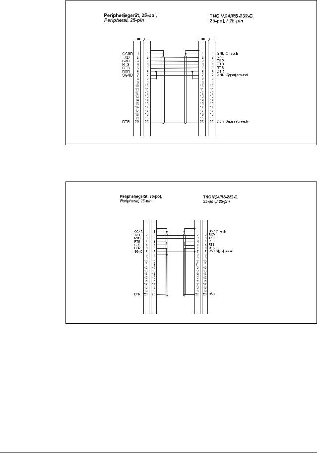
Diagram no. 11
RS-232-C/V.24 direct connection for hardware handshake,
TNC 25-pin / peripheral 25-pin (1:1)
Diagram no. 12
RS-232-C/V.24 direct connection for software handshake,
TNC 25-pin / peripheral 25-pin (1:1)
4 – 30 |
HEIDENHAIN Service Manual for Data Interfaces |
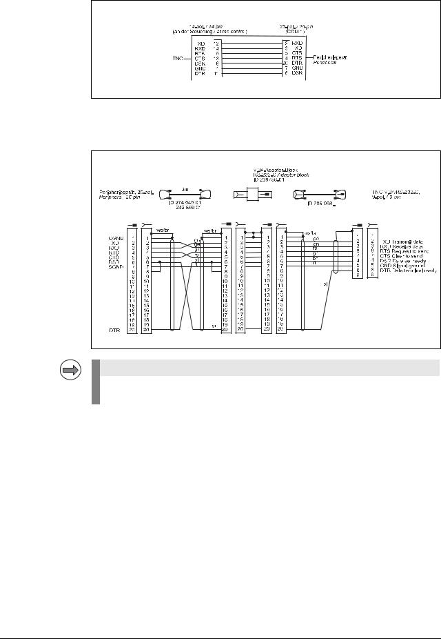
Diagram no. 13
RS-232-C /V.24 direct connection, TNC 14-pin / peripheral 25-pin
Diagram no. 14
RS-232-C/V.24 with adapter block for hardware handshake,
TNC 9-pin / peripheral 25-pin
Note |
If the pin layout of your peripheral unit differs from the above layout, the HEIDENHAIN connecting cable may not be used.
June 2011 |
4 – 31 |
Loading...