


 Loading...
Technical Manual
Functional
Safety (FS)
NC software iTNC 530 HSCI 606 420-02 606 421-02
NC software TNC 640 340 590-01 340 591-01
April 2012

Contents
1 |
Update Information |
|
|
1.1 |
General information............................................................................ |
7 |
|
1 Update Information No. 02 – Functional Safety |
|||
1.1 |
Overview.............................................................................................. |
9 |
|
|
1.1.1 |
Released service packs ............................................................ |
9 |
1.2 |
NC Software 606 42x-01 SP 06 ........................................................ |
10 |
|
|
1.2.1 |
Important notes ...................................................................... |
10 |
1 Update Information No. 03 – Functional Safety |
|||
1.1 |
Overview............................................................................................ |
13 |
|
|
1.1.1 |
Released service packs .......................................................... |
13 |
1.2 |
NC Software 606 42x-02 ................................................................... |
14 |
|
|
1.2.1 |
Important notes ...................................................................... |
14 |
|
1.2.2 New splcapimarker.def definition file ..................................... |
15 |
|
1.3 |
New Safety Functions ...................................................................... |
17 |
|
1.4 |
(S)PLC |
................................................................................................. |
21 |
1 Update Information No. 04 – functional safety
1.1 |
Overview............................................................................................ |
25 |
|
|
1.1.1 Service packs released for the iTNC 530 HSCI....................... |
25 |
|
|
1.1.2 NC software versions released for the TNC 640 .................... |
25 |
|
1.2 |
Notes |
.................................................................................................. |
26 |
|
1.2.1 NC software 340 59x-01, 606 42x-02 SP 02........................... |
26 |
|
|
1.2.2 |
General information ................................................................ |
26 |
1.3 |
NC software 340 59x-01 (TNC 640).................................................. |
27 |
|
|
1.3.1 ...................................................................................... |
Notes |
27 |
2 |
Introduction |
|
2.1 |
Meaning of the symbols used in this manual ................................ |
29 |
2.2 |
Warnings............................................................................................ |
30 |
2.3 |
Proper and intended operation........................................................ |
33 |
2.4 |
Trained personnel ............................................................................. |
33 |
2.5 |
General information.......................................................................... |
34 |
2.6 |
Overview of FS components............................................................ |
40 |
|
2.6.1 List of approved control components..................................... |
41 |
|
2.6.2 List of approved inverter components.................................... |
44 |
|
2.6.3 Differences between systems with and without |
|
|
functional safety (FS) .............................................................. |
46 |
April 2012 |
3 |

3 |
Directives and standards |
|
3.1 |
Applicable directives......................................................................... |
49 |
3.2 |
Basis for testing ................................................................................ |
50 |
3.3 |
Requirements on safety integrity.................................................... |
53 |
3.4 |
SIL and target failure measures....................................................... |
53 |
3.5 |
Storage and operating temperatures ............................................. |
53 |
3.6 |
Limit values for EM noise immunity ............................................... |
53 |
3.7 |
Mission time ...................................................................................... |
53 |
4 |
Realization and safety functions |
|
|
4.1 |
Glossary ............................................................................................. |
55 |
|
4.2 |
Realization of the HEIDENHAIN safety system .............................. |
59 |
|
4.3 |
Activation of functional safety (FS)................................................. |
59 |
|
4.4 |
(S)PLC programs ............................................................................... |
60 |
|
4.5 |
SPLC ................................................................................................... |
|
61 |
4.6 |
SKERN |
................................................................................................ |
63 |
4.7 |
Cross comparison ............................................................................. |
66 |
|
4.8 |
Description of the safety/monitoring functions ............................ |
67 |
|
|
4.8.1 |
Overview of the safety functions ........................................... |
67 |
|
4.8.2 Overview of monitoring functions .......................................... |
69 |
|
|
4.8.3 |
Safe stop 0 (SS0) .................................................................... |
70 |
|
4.8.4 |
Safe stop 1 (SS1) – Fastest possible stopping ....................... |
71 |
|
4.8.5 |
Safe stop 1D (SS1D) – Delayed SS1....................................... |
74 |
|
4.8.6 Safe stop 1F (SS1F) – Fastest possible stopping ................... |
74 |
|
|
4.8.7 |
Safe stop 2 (SS2) – Controlled stopping ................................. |
75 |
|
4.8.8 |
Summary of the stop reactions .............................................. |
79 |
|
4.8.9 |
Safe torque off (STO).............................................................. |
81 |
|
4.8.10 |
Safe operating stop (SOS) ...................................................... |
83 |
|
4.8.11 |
Safely limited speed (SLS)...................................................... |
84 |
|
4.8.12 |
Safely limited position (SLP) ................................................... |
85 |
|
4.8.13 |
Safe brake control (SBC)......................................................... |
88 |
|
4.8.14 |
Safely limited increment (SLI)................................................. |
89 |
|
4.8.15 |
Nominal-actual value comparison ........................................... |
89 |
|
4.8.16 |
Nominal-actual value comparison with position values .......... |
90 |
|
4.8.17 |
Nominal-actual value comparison with speed values ............. |
90 |
|
4.8.18 |
Protection against unexpected start-up.................................. |
91 |
|
4.8.19 |
dv/dt monitoring of the braking processes ............................. |
92 |
|
4.8.20 |
Response times, definitions, demand rates ........................... |
93 |
|
4.8.21 |
Safe status bits....................................................................... |
98 |
|
4.8.22 |
Fault reaction to safe status bits .......................................... |
101 |
|
4.8.23 |
Behavior when a fault is detected ........................................ |
103 |
|
4.8.24 |
Stop reactions depending on the fault situations ................. |
105 |
4.9 |
Special features of various software versions ............................. |
112 |
|
4.10 |
Requirements the application must meet .................................... |
116 |
|
4.11 |
Remaining risks............................................................................... |
118 |
|
4 |
HEIDENHAIN Technical Manual Functional Safety (FS) |

5 Safety-related MPs and signals |
|
|
5.1 |
Safety-related machine parameters (SMPs)................................. |
119 |
5.2 |
SMP commissioning ....................................................................... |
142 |
5.3 |
Acceptance test............................................................................... |
149 |
5.4 |
Safety-related hardware signals.................................................... |
150 |
5.5 |
Further settings............................................................................... |
154 |
6Safety-related operating modes and interfaces
6.1 Operating modes (SOM Safe Operating Modes) ......................... |
157 |
|
6.1.1 |
Operating mode 1 (SOM_1).................................................. |
158 |
6.1.2 |
Operating mode 2 (SOM_2).................................................. |
159 |
6.1.3 |
Operating mode 3 (SOM_3).................................................. |
161 |
6.1.4 |
Operating mode 4 (SOM_4).................................................. |
163 |
6.1.5 |
Operating mode – restricted spindle operation (SOM_S) ..... |
165 |
6.1.6 |
Operating mode selection – inputs....................................... |
166 |
6.1.7 |
Configuration of axis groups ................................................. |
168 |
6.1.8 |
Magazine axes ...................................................................... |
170 |
6.1.9 |
Non-safe axes and spindles .................................................. |
171 |
6.1.10 |
Electronic handwheel ........................................................... |
172 |
6.1.11 |
Use of several operating units .............................................. |
175 |
6.2 Safety-related hardware interfaces............................................... |
176 |
|
6.2.1 |
Interfaces of the SPL............................................................ |
176 |
6.2.2 |
Interfaces of the SMOP........................................................ |
186 |
6.2.2.1 |
Interfaces of the handwheel (HR)......................................... |
189 |
7Safety-Related Tests and Forced Dynamic Sampling
7.1 |
Safety Self-Test ............................................................................... |
191 |
7.2 |
Self-Test Sequence ......................................................................... |
194 |
7.3 |
Test of the cut-out channels .......................................................... |
197 |
7.4 |
Test of machine control voltage.................................................... |
198 |
7.5 |
Test of the chain of normally closed contacts ............................. |
198 |
7.6 |
Test of the guard doors .................................................................. |
198 |
7.7 |
Test of the motor brake control .................................................... |
199 |
7.8 |
Motor Brake Test ............................................................................ |
202 |
|
7.8.1 Brake test of the iTNC 530 for synchronized axes ............... |
204 |
|
7.8.2 Brake test of the TNC 6xx for synchronized axes................. |
211 |
|
7.8.3 Brake test with PLC module 9143........................................ |
215 |
7.9 |
Test of the machine configuration ................................................ |
217 |
7.10 |
Test of the machine keys and permissive buttons/keys............. |
217 |
7.11 |
Test of the emergency-stop circuit ............................................... |
217 |
April 2012 |
5 |

8 |
SPLC – safety-related PLC |
|
|
8.1 |
General information........................................................................ |
219 |
|
8.2 |
Safe software structure.................................................................. |
220 |
|
8.3 |
Software structure of PLC / SPLC ................................................. |
220 |
|
8.4 |
Glossary ........................................................................................... |
221 |
|
8.5 |
SPLC development tool.................................................................. |
223 |
|
8.6 |
PLC and SPLC programs................................................................. |
224 |
|
8.7 |
Safety of the SPLC program .......................................................... |
226 |
|
8.8 |
Requirements to be met by the SPLC program ........................... |
227 |
|
|
8.8.1 |
Axis groups / working spaces for an example |
|
|
|
milling machine..................................................................... |
227 |
|
8.8.2 |
Moving the axes with open guard doors .............................. |
228 |
8.9 |
Interfaces of the SPLC .................................................................... |
229 |
|
|
8.9.1 The splcapimarker.def definition file..................................... |
229 |
|
|
8.9.2 |
Safety-related inputs, FS inputs............................................ |
231 |
|
8.9.3 |
Safety-related outputs, FS outputs....................................... |
232 |
|
8.9.4 |
SKERN --> SPLC programming interface.............................. |
234 |
|
8.9.5 |
SPLC --> SKERN programming interface.............................. |
237 |
|
8.9.6 |
PLC --> SPLC programming interface................................... |
238 |
|
8.9.7 |
SPLC --> PLC programming interface................................... |
240 |
|
8.9.8 |
Diagnosis of the SPLC operands .......................................... |
241 |
8.10 |
Tasks of the SPLC program............................................................ |
242 |
|
|
8.10.1 Operation with open guard door........................................... |
242 |
|
|
8.10.2 Selecting a safety-related operating mode (SOM)................ |
243 |
|
|
8.10.3 |
Requirements to be met by SPLC outputs........................... |
243 |
|
8.10.4 Requirements on the data of the ApiToSafety structure...... |
246 |
|
|
8.10.5 |
Filtering of inputs.................................................................. |
265 |
8.11 |
Sample cases................................................................................... |
267 |
|
|
8.11.1 Movement of NC axes and spindle ...................................... |
267 |
|
|
8.11.2 |
Movement of the axes of the tool magazine........................ |
274 |
6 |
HEIDENHAIN Technical Manual Functional Safety (FS) |

1 Update Information
1.1 General information
Update Information for the Functional Safety Technical Manual appears at irregular intervals, often as part of a new software version. This is preliminary information in PDF format, containing brief descriptions of new software functions as well as new hardware components. After the Update Information has been published, the new items are included in the Functional Safety Technical Manual.
The Technical Manual and each Update Information are saved in the HEIDENHAIN HESIS-Web including Filebase on the Internet, where registered users can access them at http://portal.heidenhain.de.
Registered users of the HEIDENHAIN HESIS-Web including Filebase on the Internet receive an e-mail notification when a new Update Information appears.
This version of the Technical Manual includes all Update Information documents up to and including number 04, meaning that the contents of this Technical Manual correspond to the scope of functions of software version 606 42x-02 for the iTNC 530 HSCI or 340 59x-01 for TNC 640.
April 2012 |
1.1 General information |
7 |

8 |
HEIDENHAIN Technical Manual Functional Safety |

1 Update Information No. 02 – Functional Safety
1.1 Overview
1.1.1 Released service packs
The following service packs were released for 606 42x-01:
Service pack 01: August 2010
Service pack 02: December 2010
Service pack 03: February 2011
Service pack 04: March 2011 (not for functional safety)
Service pack 05: May 2011 (approved for functional safety)
Service pack 06: October 2011
(approved for functional safety)
October 2011 |
1.1 Overview |
9 |

1.2 NC Software 606 42x-01 SP 06
1.2.1 Important notes
SS1D when MP549 = 2 leads to SS2 with subsequent SOS of the axis group
In case of an SS1D for an axis group (e.g., for the spindle when releasing the permissive key while the door is open) the system until now waited until all interlinked axis groups (SMP610.x) had terminated an active SS2 or SS1D. Then all drives of the affected axis group (e.g., the spindle) were stopped with an SS1. Until now this always led to removal of power from the axis group (STO) for which the SS1D had been initiated.
As of service pack 06, if SMP549.x = 2 is set, the axis group (e.g., the spindle) for which an SS1D was initiated is braked with an SS2 after the interlinked axis groups have been braked. At standstill SOS becomes active for this axis group instead of STO. This means that in case of an SS1D or SS2 at standstill, SMP549.x = 2 leads to the SOS state.
Please note that upon SS1D this function now initiates an SS2 stop reaction for the affected axis group, and not an SS1 as previously.
SMP (iTNC 530): |
SMP549.x |
Description: |
Axis-group-specific configuration defining whether |
|
the axis group is to be switched to SOS instead of |
|
STO upon an initiated SS1D or SS2 (e.g., spindle) |
|
(used for lathes). |
Input: |
0: Default (spindle in STO, axes in SOS) |
|
1: Axis group in STO upon SS1D or SS2 |
|
2: Axis group in SOS upon SS1D or SS2 |
|
Default value: 0 |
10 |
HEIDENHAIN Technical Manual Functional Safety |
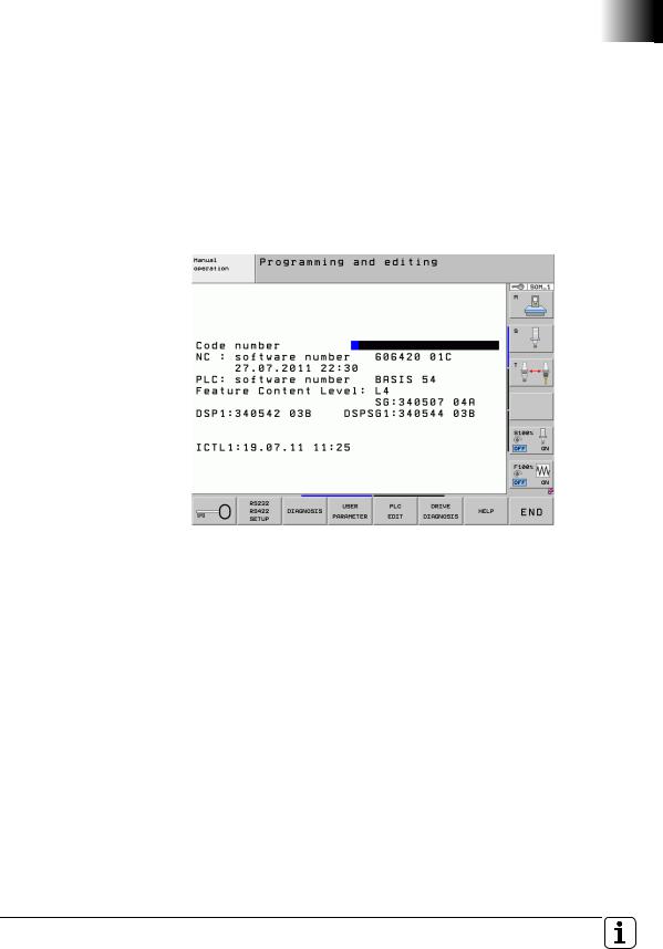
Display of the installed NC software and SKERN software
If you press the MOD key in any operating mode, the ID numbers and versions of the installed software packages are displayed:
NC : software number: NC software with date
PLC : software number: PLC program
SG: SKERN software of the MC
DSPx: DSP software of CC number x
DSPSGx: SKERN software of CC number x
ICTLx: Current controller of CC number x
October 2011 |
1.2 NC Software 606 42x-01 SP 06 |
11 |

12 |
HEIDENHAIN Technical Manual Functional Safety |

1 Update Information No. 03 – Functional Safety
1.1 Overview
1.1.1 Released service packs
The following service packs were released for 606 42x-01:
Service pack 01: August 2010
Service pack 02: December 2010
Service pack 03: February 2011
Service pack 04: March 2011 (not for functional safety)
Service pack 05: May 2011 (approved for functional safety)
Service pack 06: September 2011
(approved for functional safety)
The following software versions were released for applications with integrated functional safety (FS):
606 42x-02: |
December 2011 |
March 2012 |
1.1 Overview |
13 |

1.2 NC Software 606 42x-02
1.2.1 Important notes
Release of software |
Until now you received a HEIDENHAIN Filebase Info when a new NC software |
|
for FS applications |
version or service pack was released for applications with integrated |
|
|
functional safety (FS). The software could then be downloaded from the usual |
|
|
directories for your control via HESIS-Web including Filebase (e.g. Controls/ |
|
|
iTNC 530/Software EXLREQ). |
|
|
In order to improve the overview of which software versions have been |
|
|
released for applications with integrated functional safety (FS), new directories |
|
|
were created in HESIS-Web including Filebase. These directories have the |
|
|
additional code "FS" in their name (e.g. Controls/iTNC 530/ |
|
|
Software FS EXLREQ). Once HEIDENHAIN has released the respective NC |
|
|
software for applications with integrated functional safety, the NC software |
|
|
will be stored in these new directories. Every software version that you find in |
|
|
these FS directories has been released for applications with integrated |
|
|
functional safety (FS). You will continue to be informed about released |
|
|
software via HEIDENHAIN Filebase Infos. When downloading NC software |
|
|
from one of the existing standard directories, you will be informed that these |
|
|
software versions are not approved for use with integrated functional safety |
|
|
(FS). |
|
|
|
Note |
|
|
|
|
|
Controls using integrated functional safety (FS) from HEIDENHAIN are to |
|
|
be operated only with software versions found in the HESIS-Web including |
|
|
Filebase directories with FS in their names. |
|
|
|
|
The same applies to Technical Manuals and Update Information documents |
|
|
for functional safety. Starting immediately, these will also be in directories |
|
|
identified with "FS" (e.g. Controls/iTNC 530/Documentation FS OEM). |
|
PLC outputs |
Single-channel outputs (standard PLC outputs) configured as output type 3 |
|
|
(switch-off upon EMERGENCY STOP) with IOconfig until now were not |
|
|
switched off automatically upon an emergency stop. The PLC program had to |
|
|
switch the outputs off. With software version 02 these single-channel PLC |
|
|
outputs will be switched off automatically when an external or internal |
|
|
emergency stop is initiated. The outputs remain switched off until the |
|
|
emergency-stop is rescinded and the control voltage has been switched back |
|
|
on. Just rescinding the emergency-stop situation does not suffice to switch |
|
|
these outputs back on. |
|
14 |
HEIDENHAIN Technical Manual Functional Safety |
1.2.2 New splcapimarker.def definition file
Software version 606 42x-02 contains a slightly modified splcapimarker.def definition file (version 56). However, the modifications are only preparatory measures for future enhancements. In software version 02 they do not result in any direct improvements of any functions. The number of possible axes was raised from 18 to 22, which shifts the spindle index to 22. This change results in a new memory layout of the SPLC run-time system, which necessitates a new acceptance test. Version 55 of splcapimarker.def must be replaced by version 56 after the software update.
Proceed as follows:
Replace the splcapimarker.def file:
During the update of the NC software, a new version of splcapimarker.def was automatically copied to the PLC partition of the control.
Switch to the Programming and Editing operating mode.
Enter the MOD code number 807667 to switch to the PLC Programming mode of operation.
Press the PGM MGT key to open the file manager.
Switch to the PLC:\proto\plc directory.
Copy splcapimarker.def to the program directory of your SPLC program. Overwrite the existing splcapimarker.def file.
Change the entry in SMP693 for the new SPLC-API version to 56.
Put the change in SMP693 into effect after rebooting the control by using the OEM password
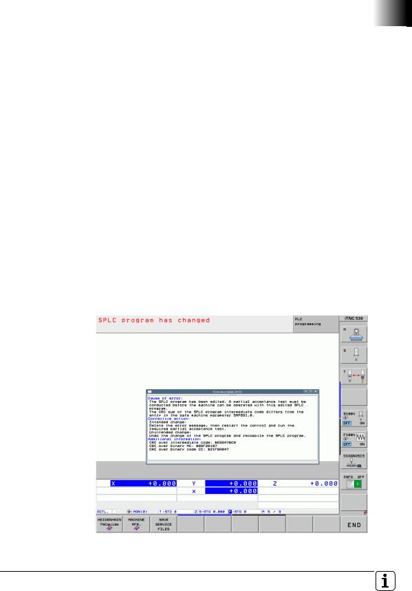
Check and compile the SPLC program with the new splcapimarker.def file. The following message than appears, since the intermediate and binary code of the SPLC program has changed:
March 2012 |
1.2 NC Software 606 42x-02 |
15 |

Included in the message, under the heading "Additional information," are the new CRC checksums for the intermediate code, binary code MC and binary code CC. Enter these values in SMPs 691.0, 691.1 and 691.2.
Put the changes in SMP691.x into effect after rebooting the control by using the OEM password.
Note
Please also copy the splcapimarker.def file to your PC as well, and add it to the PLCdesignNT project. Otherwise, during the next transfer of SPLC project files to the control, the file might be overwritten by the old version.
The SPLC-API programming interface can also be included in the standard PLC program (INCLUDE). If this is the case, the data from ApiFromSafety and ApiToSafety are copied to the double-word range of the PLC. This data can then be used for additional interrogations or diagnostic purposes in the PLC program.
Since the number of possible axes was raised from 18 to 22 (indexes 0 to 21), the index of the first spindle is shifted to 22. Please take this into account in your SPLC program, and make any necessary adjustments. So that you don't always have to modify the SPLC program when there are such changes in the future, HEIDENHAIN recommends using the constant FIRST_SPINDLE for the spindle in the SPLC program.
Danger
You must subject the machine to a new acceptance test, as a consequence of the changed SPLC-API version.
16 |
HEIDENHAIN Technical Manual Functional Safety |
1.3New Safety Functions
Extended SPLC diagnostics
•A predefined watch list is available for the static diagnosis of the SPLC markers defined in splcapimarker.def. It can be called from the PLC diagnostics via the WATCH LIST soft key and the program manager (PGM MGT key). The file can be found at: PLC:\DEBUG\SPLCAPI.WLT
•Under the DIAGNOSIS soft key in the PLC operating mode there is another soft key: GENERATE TRACE FILES. Pressing it triggers the generation of HSCI and SPLC trace files. These files (xxx.trace and xxx.sco) are stored in the folder PLC:\DEBUG\.
Display of the installed NC software and SKERN software
If you press the MOD key in any operating mode, the ID numbers and versions of the installed software packages are displayed:
NC : software number: NC software with date
PLC : software number: PLC program
SG: SKERN software of the MC
DSPx: DSP software of CC number x
DSPSGx: SKERN software of CC number x
ICTLx: Current controller of CC number x
Standstill monitoring in SOS state
If, however, the maximum permissible path defined in SMP545.x (limit value for standstill monitoring in [mm] or [°]) was exceeded while adhering to the limit values for the spindle speed and axis feed rate in SOS, the SS0 safety function was initiated globally for all axes, and SS1 for the spindles. Now an SS0 reaction is initiated for the affected drive (axis or spindle), and an SS1F reaction for all other drives.
March 2012 |
1.3 New Safety Functions |
17 |

Standstill monitoring of the spindle with SS2
The new machine parameters SMP556, SMP557 and SMP558 can be used to specify a maximum value for standstill monitoring of the spindle upon on SS2 reaction. If the permitted number of spindle revolutions are exceeded during the SS2 reaction, an SS1 reaction is initiated.
•SMP556 - Maximum value for standstill monitoring during SS2 of spindle in SOM_2
Input: |
1 to 100 [revolutions] |
|
Default value = 2 |
•SMP557 - Maximum value for standstill monitoring during SS2 of spindle in SOM_3
Input: |
1 to 100 [revolutions] |
|
Default value = 5 |
•SMP558 - Maximum value for standstill monitoring during SS2 of spindle in SOM_4
Input: |
1 to 100 [revolutions] |
|
Default value = 5 |
MP1310.x – Sequence for approaching the test positions
The axis sequence of the soft keys for approaching the test positions can now be configured with MP1310. As previously, the operator can change the sequence by selecting the soft keys. The parameter index determines the position of the soft key in the soft-key row. The value of the parameter defines the axis to be displayed in the soft-key image in reference to MP100. All parameters after a programmed value 0 are not taken into consideration. The remaining safe axes is shown in the same sequence as in MP100. If a negative value is entered, the axis is shown in gray, and only becomes active once the axes with positive entries have been moved to the reference point or the operator selects the axis.
Example:
MP100: CBAaZYX MP1310.0: 7 MP1310.1: 6 MP1310.2: -4
MP1310.3: 0
Soft-key row: C B a X Y Z A a=gray
Input in MP1310.x:
1 to 18 [number indicating the axis' position in the test sequence] 0 = Not active
Displaying the distance-to-go during axis check
During the automatic movement of an axis in the "Check axis position" mode to the test position, the distance-to-go display showed the distance remaining to the software limit switch instead of the distance remaining to the test position. Now, for approaching the test position and for incremental jog, the distance remaining to the target is displayed.
Analog axes via CMA-H
As of software version 606 42x-02, analog axes can be configured and operated via the CMA-H module. The integrated functional safety from HEIDENHAIN does not monitor analog axes. Monitoring, switch-off, etc. must occur through suitable external circuitry.
18 |
HEIDENHAIN Technical Manual Functional Safety |

SS1D when MP549 = 2 leads to SS2 with subsequent SOS of the axis group
In case of an SS1D for an axis group (e.g., for the spindle when releasing the permissive key while the door is open) the system until now waited until all interlinked axis groups (SMP610.x) had terminated an active SS2 or SS1D. Then all drives of the affected axis group (e.g., the spindle) were stopped with an SS1. Until now this always led to removal of power from the axis group (STO) for which the SS1D had been initiated.
As of NC software version 606 42x-01 SP 06, if SMP549.x = 2 is set, the axis group (e.g., the spindle) for which an SS1D was initiated is braked with an SS2 after the interlinked axis groups have been braked. At standstill SOS becomes active for this axis group instead of STO. This means that in case of an SS1D or SS2 at standstill, SMP549.x = 2 leads to the SOS state. Please note that upon SS1D this function now initiates an SS2 stop reaction for the affected axis group, and not an SS1 as previously.
SMP (iTNC 530): |
SMP549.x |
Description: Axis-group-specific configuration defining whether the axis group is to be switched to SOS instead of STO upon an initiated SS1D or SS2 (e.g., spindle) (used for lathes).
Input: |
0: Default (spindle in STO, axes in SOS) |
1:Axis group in STO upon SS1D or SS2
2:Axis group in SOS upon SS1D or SS2 Default value: 0
Protection against unexpected movement with SMP 549.x = 2
If SMP549.x = 2 for the axis group (including spindles), the axis group now remains in the SOS state or under control in the following cases even while at standstill. This means that there is no automatic transition to STO:
•if the permissive key or button is not pressed at standstill or while in the SOS state.
•if the override potentiometers are at 0% when guard doors are opened.
•if M19 is active when guard doors are open (only for spindle axis group).
March 2012 |
1.3 New Safety Functions |
19 |
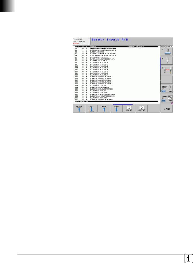
Diagnosis of the SPLC inputs and outputs
In the PLC programming mode (code number 807667) the last soft-key row under the table function (TABLE soft key) has a soft-key called S-PLC DIAGNOSIS. There you will find a list of all FS inputs and FS outputs, along with their current state. The regular FS outputs as well as the "special" outputs, such as TEST.A, TEST.B, STO.A.G and STOS.A.G, are also shown. The table shows the operand address, the state of the A and B channel inputs, and the symbolic name.
Fault reaction to safe status bits
Until now, if –PF.PS.DC was active, the watchdogs of the MC were not retriggered. The other HSCI participants therefore detected the MC as being defective, and it was not possible to switch off the DC-link voltage without an error message. Until now the CC initiated an SS1 reaction. The SKERN MC and CC now no longer evaluate the -PF.PS.DC status bit, and there is no longer a reaction by the SKERN.
20 |
HEIDENHAIN Technical Manual Functional Safety |
1.4 (S)PLC
The PLC Module 9143 for triggering the brake test can now also be used in systems with functional safety. The brake test during the safety self-test is not affected by this, and continues to test the motor holding brake. It is now possible, via this module and the (S)PLC program, regardless of the self-test, to test the motor holding brakes at any time for specific axes, and even for specific brakes of an axis. The module only tests the holding torque of the brake, but not the dual-channel controllability of the brake. The dual-channel controllability is still part of the self-test. The procedure for testing two brakes of an axis via Module 9143 could be as follows:
The SPLC program controls the opening and closing of the brake simultaneously for the motor holding brake and the supplementary brake
The SPLC program controls the opening and closing of the brake only for the motor holding brake
The supplementary brake is opened
PLC Module 9143 performs the brake test for the motor holding brake
The SPLC program controls the opening and closing of the brake simultaneously for the motor holding brake and the supplementary brake
The SPLC program controls the opening and closing of the brake only for the supplementary brake
The motor holding brake is opened
PLC Module 9143 performs the brake test for the supplementary brake
The SPLC program controls the opening and closing of the brake simultaneously for the motor holding brake and the supplementary brake
Module 9143 Activate the brake test
With this module an axis-specific brake test with the configuration from the machine parameters or with other values for MPs 2230 and 2232 can be started. Refer also to the information in the Technical Manual of your control.
Constraints:
Synchronized axes
For synchronized axes, only the brake test of the master can be configured and requested via the PLC module. If a brake test for an associated slave drive of the synchronized axis is configured via MP2230.x, then the slaves are automatically tested together with the master. The settings in the machine parameters are used for the brake test of the slave drives.
In order to start the brake test of synchronized axes via PLC Module 9143, all drives of a synchronized axis must be switched on via the PLC program before the brake test can be performed. If a servo drive involved is not switched on, the brake test is canceled with the error message 8330 Brake test was canceled.
Programming it in a submit job blocks other submit jobs until the test is completed.
The PLC module automatically passes the processing time to other spawn and submit processes.
March 2012 |
1.4 (S)PLC |
21 |

Call: |
|
|
PS |
K/B/W/D |
<>Axis number> |
|
|
0 = 1st axis, 1 = 2nd axis, etc. |
PS |
K/B/W/D |
<>Multiplier for motor stall current> |
|
|
Value in 1/1000 or |
|
|
0: Default MP2230 (factor of nominal current) |
PS |
K/B/W/D |
<>Permissible traverse path> |
|
|
Value in 0.1 [um] or |
|
|
0: Default MP2232 |
CM |
9143 |
|
PL |
B/W/D |
<>Status/Error> |
0:Brake OK
1:Brake defective
2:Invalid axis or negative values for rated current or traverse path
3:Call during running NC program or during other PLC jobs
4:Call was made from a cyclic PLC program
5:Error during data exchange
6:Not allowed for safe control
7:Drive not ready
8:Brake test was canceled (e.g. by emergency stop)
Error recognition:
Marker |
Value |
Meaning |
|
|
|
M4203 |
0 |
No error |
|
|
|
|
1 |
Error code in W1022 |
|
|
|
W1022 |
2 |
Invalid axis programmed (invalid axis number, not a |
|
|
closed-loop axis, axis currently open-loop axis or slave |
|
|
axis) or negative values for the traverse path or current |
|
|
are programmed |
|
|
|
|
8 |
Module is not allowed for control with functional |
|
|
safety |
|
|
|
|
20 |
Module was not called in a spawn job or submit job |
|
|
|
|
21 |
Call during program run or during other active PLC jobs |
|
|
for the programmed axis |
|
|
|
|
40 |
Drive not ready |
|
|
|
|
45 |
Canceled due to error during data exchange or due to |
|
|
external influences (e.g. emergency stop) |
|
|
|
22 |
HEIDENHAIN Technical Manual Functional Safety |

Module 9037 Read FS status information
PLC Module 9037 determines safety-oriented information. The number of the desired information, and possibly another number (for certain information) must be programmed in the module.
Constraints:
Only for HSCI-based systems with SPLC can the time until the next self-test be interrogated via number 4.
The causes for the stop reactions (number 7) are not stored statically. The values are only set for the time in which the stop reaction occurs.
Call: |
|
|
|
|
PS |
B/W/D/K/S<>Number of the status information> |
|||
|
|
|
0 to 3: Reserved |
|
|
|
|
4: Time until the next self-test |
|
|
|
|
5: Spindle speed at open guard door |
|
|
|
|
6: Axis feed rate with open guard door |
|
|
|
|
7: Stop reaction of axis group |
|
PS |
B/W/D/K |
<>Number of the additional information> |
||
|
|
|
For info 5: Spindle number starting with 0 |
|
|
|
|
For info 6: Axis number starting with 0 |
|
|
|
|
For info 7: Axis-group number starting with 0 |
|
CM |
9037 |
|
|
|
PL |
B/W/D |
<>Type of operand> |
||
|
|
|
0: Error |
|
|
|
|
Response from the status information |
|
|
|
|
For info 4: Time until the next self-test in seconds |
|
|
|
|
For info 5: Spindle speed at open guard door in 0.001 [1/min] |
|
|
|
|
For info 6: Feed rate with open guard door in 0.001 [mm/ |
|
|
|
|
min] or [°/min] |
|
|
|
|
For info 7: Stop reaction of axis group |
|
|
|
|
(0 = no stop reaction, 1 = SS2, 2 = SS1D, 3 = SS1, |
|
|
|
|
4 = SS1F, 5 = SS0) |
|
Error recognition: |
||||
|
|
|
|
|
Marker |
Value |
|
Meaning |
|
|
|
|
|
|
M4203 |
0 |
|
No error |
|
|
|
|
|
|
|
|
1 |
|
Error code in W1022 (also see return values of the |
|
|
|
|
module) |
|
|
|
|
|
W1022 |
1 |
|
Invalid number of the status information |
|
|
|
|
|
|
|
|
2 |
|
Invalid number of the axis group, axis or spindle |
|
|
|
|
|
|
|
43 |
|
The module was called in a control without integrated |
|
|
|
|
functional safety |
|
|
|
|
|
|
|
51 |
|
This status information is not supported by this |
|
|
|
|
system |
|
|
|
|
|
March 2012 |
1.4 (S)PLC |
23 |

24 |
HEIDENHAIN Technical Manual Functional Safety |

1 Update Information No. 04 – Functional Safety
1.1 Overview
1.1.1 Service packs released for the iTNC 530 HSCI
The following service packs for software version 606 42x-01 will be released for applications with integrated functional safety (FS):
Service pack 02: April 2012
NC software 606 42x-02 service pack 01 was not approved for applications with integrated functional safety (FS).
1.1.2 NC software versions released for the TNC 640
The following software versions were released for applications with integrated functional safety (FS):
340 59x-01: |
April 2012 |
Hinweis
Controls using integrated functional safety (FS) from HEIDENHAIN are to be operated only with software versions that are identified by FS in their names in the HESIS-Web including Filebase directories of your control.
Software versions that are not identified by FS in their names in the HESISWeb including Filebase directories of your control are not approved for use in applications with integrated functional safety (FS).
April 2012 |
1.1 Overview |
25 |

1.2 Notes
1.2.1NC software 340 59x-01, 606 42x-02 SP 02
Protection against unexpected start-up
Up to now, the protection against unexpected start-up was disabled by pressing a valid permissive button/key, which sets the interface signal pp_AxGrpPB to 1. With software versions 340 59x-01 and 606 42x-
02 SP 02, the same behavior is enabled for the interface signal pp_AxGrpActivate, which disables the activation of the protection against unexpected startup if it is set to 1. As a result, the automatic transition to SOS/STO state (transition from SLS --> SOS) is also prevented at feed rates < 50 mm/min by merely pressing an axis key (pp_AxGrpActivate = 1).
SMP549.x is effective only for the axis group of the spindles
The setting in SMP549.x is effective only for the axis group of the spindles. SMP549.x does not take effect for axis groups of NC or PLC axes.
SMP (iTNC 530): |
SMP549.x |
Description: |
Axis-group-specific configuration defining whether |
|
the axis group of the spindle is to be switched to SOS |
|
instead of STO after SS1D or SS2 has been triggered |
|
(used for lathes). |
Input: |
0: Default (spindle in STO, axes in SOS) |
|
1: Axis group of the spindle in STO upon SS1D or SS2 |
|
2: Axis group of the spindle in SOS upon SS1D or SS2 |
|
Default value: 0 |
1.2.2General information
Use of non-HEIDENHAIN encoders for safe axes/spindles for HEIDENHAIN control systems with functional safety (FS) HEIDENHAIN cannot make any statement regarding the use of non-
HEIDENHAIN encoders for the safe monitoring of axes/spindles in control systems with functional safety (FS). Your contact person at HEIDENHAIN will be glad to assist you in finding suitable HEIDENHAIN encoders for your safe applications.
Basic circuit diagram – leading main-switch contact
The leading main-switch contact that is proposed in the present HEIDENHAIN basic circuit diagram is only intended for electrical protection of the machine's main switch. The leading contact opens the main contactor in the UV(R) before the main switch separates the connection to the power line. This means that the main switch always separates the connection while the system is not under power, even if the user accidentally switches off the machine via the main switch while the drives are still in closed-loop control. When using a leading contact, please keep in mind the associated residual risks described in Chapter 4.11 of the Functional Safety (FS) Technical Manual.
HEIDENHAIN merely wanted to point out that there is the possibility of using a leading contact. However, you need not use a leading contact. It will be omitted from the future versions of the basic circuit diagram. Without this contact, the control behaves in the same way as during a power failure when it is switched off via the main switch, i.e. the drives are decelerated at the limit of current upon switch-off.
26 |
HEIDENHAIN Technical Manual Functional Safety (FS) |

1.3 NC software 340 59x-01 (TNC 640)
1.3.1 Notes
Missing functions The following functional safety (FS) functions are not contained in software version 340 59x-01 of the TNC 640 in comparison with software version 606 42x-02 of the iTNC 530:
New "SPlcApiMarker.def version 56" definition file
The TNC 640 with software version 01 is still using SPlcApiMarker.def version 55.
Standstill monitoring of the spindle upon SS2 (SMP556, SMP557, SMP558)
Operating-mode-specific monitoring of the SS2 reaction of the spindle is not yet possible with the TNC 640. In every SOM_x operating mode, the
TNC 640 uses the entry in SMP distLimitStop2 for SS2 monitoring of the spindle.
Sequence for approaching the test positions
On the iTNC 530, the axis sequence of the soft keys for approaching the test positions can be configured using MP1310. This is not yet possible on the TNC 640 with software version 01.
Handwheels
The HR 5xx handwheels with display are not yet supported by software version 01 of the TNC 6xx.
Software version 340 59x-01 of the TNC 640 is identical to software version 606 42x-02 of the iTNC 530 HSCI in all other functional safety (FS) functions.
SPLC program |
Please note that an SPLC program of the iTNC 530 needs to be modified for |
|
use on the TNC 640. In particular, the spindle index in the SPLC program is |
|
different. With the iTNC 530, the spindle is always assigned to the last index |
|
(this is index 22 in SPlcApiMarker.def version 56). With the TNC 640, the |
|
spindle is assigned to the index defined via axisList. |
Documentation |
The previous Functional Safety (FS) Technical Manual for the iTNC 530 HSCI |
|
was enhanced with regard to the TNC 640. This Technical Manual covers both |
|
controls. Differences that need to be kept in mind are indicated in this Update |
|
Information and in the Technical Manual (e.g. machine parameters of the |
|
TNC 640 are identified by "NCK-SMP:".) |
April 2012 |
1.3 NC software 340 59x-01 (TNC 640) |
27 |

28 |
HEIDENHAIN Technical Manual Functional Safety (FS) |
2 Introduction
2.1 Meaning of the symbols used in this manual
Danger
Failure to comply with this information could result in most serious or fatal injuries, and/or in substantial material damage.
Attention
Failure to comply with this information could result in injuries and interruptions of operation, including material damage.
Note
Tips and tricks for operation as well as important information, for example about standards and regulations as well as for better understanding of the document.
April 2012 |
2.1 Meaning of the symbols used in this manual |
29 |

2.2 Warnings
Danger
The functional safety as provided by HEIDENHAIN only handles the safety functions stated and described in this manual. Functional safety can reduce the inherent risks of machine tools. However, it is impossible to implement safety measures that ensure that nothing will ever go wrong with a machine tool.
In order for functional safety to take effect, the machine manufacturer must do the following:
Verify the theoretical and actual setup of the machine tool, the necessary (S)PLC programs and the machine-parameter settings with a thoroughly documented acceptance test. This acceptance test must be performed by qualified personnel.
Thoroughly understand the information contained in this manual and other documentation for the control and other electronic components being used (such as inverters and motors), as well as understand and enforce the safety instructions, constraints and relevant standards.
Draw up a risk analysis, as required by the EC machinery directive.
implement all measures deemed necessary based on the risk analysis of the machine. These measures may be implemented as a part of functional safety, or with other suitable equipment or procedures. All measures must be validated.
30 |
HEIDENHAIN Technical Manual Functional Safety (FS) |
Loading...