


 Loading...
Operating Instructions
POSITIP 880
English (en) 12/2008

POSITIP 880 Back View
Axis ports
Parallel port Edge finder
Auxiliary
 Machine
Interface connector
Ground |
|
|
Serial |
Power button |
port |
Main power input
Remote console
Keypad and soft keys
4 axis keys to select between X, Y and Z axes
Clear entry or error messages
Incremental dimensions
Keys for selecting operating mode (for detailed description of these key functions, see Operating Modes in chapter I-2)
Soft keys - Row of keys under the screen of the POSITIP whose functions vary according to associated fields that appear above them on the screen
Numeric input keys
Change negative/positive value key
Confirm entry
Select entry fields

General Notes
Software version
The software version of your unit is shown on the initial power up screen and on the prompt bar after pressing the Help soft key.
This User's Manual covers the functions of the POSITIP 880 for both milling and turning applications. Basic POSITIP 880 functions are covered in the first 4 chapters of this manual. The turning section deals only with the functions specific to turning applications.
About this manual
This manual is divided into two parts:
Part I: Operating Instructions
Part II: Technical Information
Operating Instructions
When using the POSITIP 880 in your work, you need only refer to the Operating Instructions (Part I).
If you're new to POSITIP 880, you can use the operating instructions as a step-by-step workbook. This part begins with a short introduction to the basics of coordinate systems and position feedback, and provides an overview of the available features. Each feature is explained in detail, using an example which you can immediately try out on the machine — so you won't get "lost" in the theory. As a beginner you should work through all the examples presented.
If you're already familiar with POSITIP 880, you can use the Operating Instructions as a comprehensive review and reference guide.
Technical Information
If you are interfacing the POSITIP 880 to a machine or wish to use the data interfaces, refer to the technical information in Part II.
Dialog flowcharts
Dialog flowcharts are used for each example in this manual. They are laid out as follows:
General Notes
POSITIP 880 |
3 |

General Notes
PROMPT
This area explains the key function or work step. If KEY necessary, supplementary information will also be
included.
If there is an arrow at the end of the flowchart, this means that it continues on the next page.
A perforated line indicates an alternative method of carrying out the given function.
A prompt appears with some actions (not always) in the message bar on the screen.
Important Notes in this Manual
Special green note boxes contain especially important information. Please pay special attention to these notes. Neglecting this information can result in e.g. functions not working in the desired way or in causing damage to the workpiece or to the tool.
4

Symbols within the notes
Every note is marked with a symbol on the left informing about the meaning of the note.
General Information
e.g. on the behavior of the POSITIP 880.
Warning – Refer to accompanying documents
e.g. when a special tool is required for a function.
Caution - Risk of electric shock
e.g. when opening a housing.
General Notes
POSITIP 880 |
5 |

I Operating Instructions ..... |
11 |
I – 1 Fundamentals of Positioning ..... |
12 |
|
|
|
|
|
|||
Coordinate Systems ..... |
12 |
|
|
|
|
|
|
||
Setting the Datum ..... |
13 |
|
|
|
|
|
|
||
Nominal Position, Actual Position and Distance-To-Go ..... |
14 |
|
|||||||
Absolute Workpiece Positions |
..... 15 |
|
|
|
|
|
|||
Incremental Workpiece Positions ..... |
15 |
|
|
|
|||||
Position Encoders ..... |
17 |
|
|
|
|
|
|
||
Reference Marks |
..... |
17 |
|
|
|
|
|
|
|
Angle Reference Axis |
..... 18 |
|
|
|
|
|
|
||
I – 2 Working with POSITIP 880 – First Steps |
..... 19 |
|
|
|
|||||
Power Up ..... |
19 |
|
|
|
|
|
|
|
|
Before You Start ..... |
19 |
|
|
|
|
|
|
||
Operating Modes |
..... |
21 |
|
|
|
|
|
|
|
On-Screen Operating Instructions (HELP Mode) ..... |
22 |
|
|
||||||
Confirming Your Changes ..... |
22 |
|
|
|
|
|
|||
Messages ..... |
23 |
|
|
|
|
|
|
|
|
Error messages ..... |
23 |
|
|
|
|
|
|
||
Selecting the Unit of Measure |
..... 24 |
|
|
|
|
|
|||
Selecting the Angle Format ..... |
24 |
|
|
|
|
|
|||
Tool Table ..... |
24 |
|
|
|
|
|
|
|
|
Calling the Tool Data ..... |
25 |
|
|
|
|
|
|
||
I – 3 Actual Value ..... |
26 |
|
|
|
|
|
|
|
|
Datum Setting: Approaching Positions and Entering Actual Values ..... |
26 |
||||||||
Probing Functions for Datum Setting |
..... |
28 |
|
|
|
||||
Datum Setting with a Tool ..... |
34 |
|
|
|
|
|
|||
I – 4 Distance-To-Go ..... |
|
36 |
|
|
|
|
|
|
|
Displaying and Moving to Positions ..... |
|
36 |
|
|
|
||||
I – 5 Milling Patterns ..... |
|
43 |
|
|
|
|
|
|
|
Circle Pattern ..... |
|
43 |
|
|
|
|
|
|
|
Linear Pattern |
..... |
46 |
|
|
|
|
|
|
|
Milling a Rectangle Pocket ..... |
49 |
|
|
|
|
|
|||
POSITIP 880 |
7 |
I – 6 Programming POSITIP 880 ..... |
53 |
|
|
||||
Program Capabilities |
..... 53 |
|
|
||||
Editing and moving through a program |
..... 53 |
|
|||||
Programming Features ..... |
54 |
|
|
||||
Tool Call ..... |
56 |
|
|
|
|
|
|
Datum Call ..... |
57 |
|
|
|
|
||
Presets ..... |
58 |
|
|
|
|
|
|
Hole Patterns and Rectangle Patterns ..... |
59 |
|
|||||
Subprograms ..... |
|
59 |
|
|
|
|
|
Labels ..... |
59 |
|
|
|
|
|
|
Label Number ..... |
60 |
|
|
|
|
||
Label Call |
..... |
60 |
|
|
|
|
|
Position Drill ..... |
62 |
|
|
|
|
||
Milling a Line ..... |
|
63 |
|
|
|
|
|
Milling an Arc |
..... |
64 |
|
|
|
|
|
Blend ..... |
66 |
|
|
|
|
|
|
Chamfer ..... |
68 |
|
|
|
|
|
|
File Operation Soft Keys ..... |
70 |
|
|
||||
Loading, saving, deleting & clearing a program ..... |
70 |
||||||
Directories ..... |
71 |
|
|
|
|
||
Importing a Program ..... |
73 |
|
|
||||
Exporting a Program ..... |
74 |
|
|
|
|||
Block Function Soft Keys ..... |
74 |
|
|
||||
I – 7 Executing a Program ..... |
78 |
|
|
|
|||
Program views ..... |
80 |
|
|
|
|||
Contour View |
..... |
81 |
|
|
|
|
|
I – 8 INFO Screen ..... |
83 |
|
|
|
|
|
|
JOB SETUP Menu ..... |
83 |
|
|
|
|||
Tool Table Usage |
..... |
85 |
|
|
|
||
Installation Menu |
..... |
92 |
|
|
|
||
Calculator |
..... |
92 |
|
|
|
|
|
Language |
..... |
95 |
|
|
|
|
|
Inch/MM ..... |
95 |
|
|
|
|
|
|
8
I – 9 POSITIP 880 Turning Functions ..... |
96 |
|
|
||||
Power Up ..... |
96 |
|
|
|
|
|
|
Fundamentals of Positioning |
..... 97 |
|
|
||||
Job Setup for Turning Applications ..... |
98 |
|
|||||
Tool Table Usage ..... |
99 |
|
|
|
|
|
|
Tool Offsetting ..... |
102 |
|
|
|
|
|
|
NOTE/SET Function ..... |
103 |
|
|
|
|
||
Datum Setting ..... |
104 |
|
|
|
|
|
|
Taper Calculator ..... |
104 |
|
|
|
|
|
|
Programming Turning Functions for POSITIP 880 ..... |
106 |
||||||
Programming Features Soft Keys |
..... |
106 |
|
||||
Multipass ..... |
107 |
|
|
|
|
|
|
File Operation Soft Keys |
..... |
108 |
|
|
|
||
Block Function Soft Keys ..... |
109 |
|
|
|
|||
POSITIP 880 |
9 |
.....II Technical Information |
111 |
|
|
|
|
|||
II – 1 Installation and Electrical Connection |
..... |
112 |
|
|
||||
Items Supplied ..... |
112 |
|
|
|
|
|
|
|
Mounting Location |
..... 112 |
|
|
|
|
|
||
Installation ..... |
112 |
|
|
|
|
|
|
|
Connecting the Encoders ..... |
114 |
|
|
|
|
|||
Connecting an Edge Finder |
..... 115 |
|
|
|
|
|||
II – 2 Installation Setup ..... |
116 |
|
|
|
|
|
|
|
Initial switch-on ..... |
116 |
|
|
|
|
|
|
|
General field/form navigation guide ..... |
|
117 |
|
|
||||
Axes Configuration |
..... 117 |
|
|
|
|
|
||
Encoder Setup ..... |
118 |
|
|
|
|
|
|
|
Error Compensation ..... |
119 |
|
|
|
|
|||
Linear Error Compensation |
..... 120 |
|
|
|
|
|||
Non-Linear Error Compensation ..... |
121 |
|
|
|||||
Serial Port (X31) ..... |
123 |
|
|
|
|
|
|
|
Parallel Port (X32) ..... |
123 |
|
|
|
|
|
||
Protection ..... |
124 |
|
|
|
|
|
|
|
Counter Settings ..... |
124 |
|
|
|
|
|
||
Diagnostics ..... |
125 |
|
|
|
|
|
|
|
AMI (Auxiliary Machine Interface)(X51) (Optional) |
..... |
126 |
||||||
Remote Console (X61) (Optional) ..... |
|
127 |
|
|
||||
II – 3 Encoders and Measured Value Display ..... |
128 |
|
|
|||||
Setting the display step with rotary encoders ..... |
129 |
|
||||||
II – 4 Data Interface ..... |
130 |
|
|
|
|
|
|
|
II – 5 Measured Value Output ..... |
135 |
|
|
|
|
|||
Examples of character output at the data interface ..... |
135 |
|||||||
II – 6 Specifications for Milling ..... |
|
139 |
|
|
|
|
||
II – 7 Specifications for Turning |
..... |
141 |
|
|
|
|
||
II – 8 Dimensions ..... |
143 |
|
|
|
|
|
|
|
II – 9 Accessories ..... |
144 |
|
|
|
|
|
|
|
Accessory ID Numbers ..... |
|
144 |
|
|
|
|
||
POSITIP 880 Mounting Instructions |
|
|
|
|
||||
Universal Mounting Arm |
|
|
|
|
|
|
||
ld. Nr. 382 929-01 ..... |
145 |
|
|
|
|
|
||
POSITIP 880 Mounting Instructions |
|
|
|
|
||||
Mounting base |
|
|
|
|
|
|
|
|
ld. Nr. 382 892-01 ..... |
146 |
|
|
|
|
|
||
POSITIP 880 Mounting Instructions |
|
|
|
|
||||
Tilt/Swivel Mount |
|
|
|
|
|
|
|
|
ld. Nr. 382 891-01 ..... |
147 |
|
|
|
|
|
||
10
Operating Instructions
11
I – 1 Fundamentals of Positioning
I – 1 Fundamentals of Positioning
You can skip over this chapter if you are familiar with the concepts of coordinate systems, incremental and absolute dimensions, nominal and actual positions, and distance-to- go.
Coordinate Systems
In order to define positions on a surface, a reference system is required.
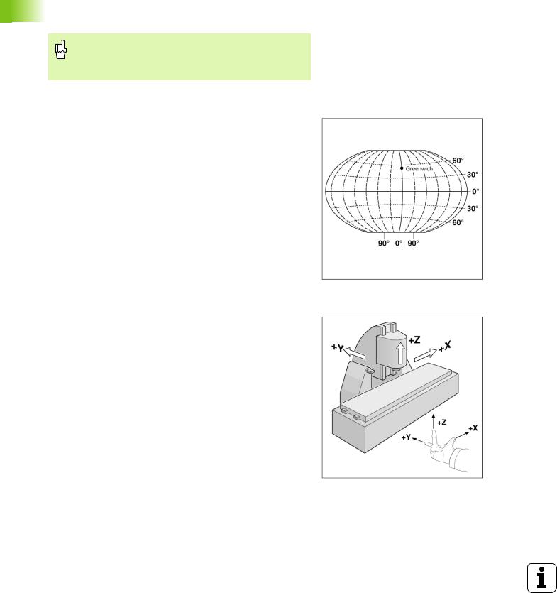
For example, positions on the earth's surface can be defined absolutely by their geographic coordinates of longitude and latitude. In contrast to the relative definition of a position that is referenced to a known location, the network of horizontal and vertical lines on the globe constitute an absolute reference system. See Fig. I.1.
Fig. I.1
On a milling machine, workpieces are normally machined according to a workpiece-based Cartesian coordinate system (a rectangular coordinate system named after the French mathematician and philosopher Renatus Cartesius, who lived from 1596 to 1650). The Cartesian coordinate system is based on three coordinate axes designated X, Y and Z which are parallel to the machine guideways.
The figure to the right (Fig. I.2) illustrates the right-hand rule for remembering the three axis directions: the middle finger is pointing in the positive direction of the tool axis from the workpiece toward the tool (the Z axis), the thumb is pointing in the positive X direction, and the index finger in the positive Y direction.
The geographic coordinate system is an absolute reference system
Fig. I.2 Designations and directions of the axes on a milling machine
12 |
I Operating Instructions |

Setting the Datum
The workpiece drawing (Fig. I.3) identifies a certain point on the workpiece (usually a corner) as the absolute datum and perhaps one or more other points as relative datums.
The datum setting procedure establishes these points as the origin of the absolute or relative coordinate systems: The workpiece, which is aligned with the machine axes, is moved to a certain position relative to the tool and the display is set either to zero or to another appropriate value (e.g., to compensate the tool radius).
Example:
Drawing with several relative datums (ISO 129 or DIN 406 Part 11,
Fig. 171)
Fig. I.3 The workpiece datum represents the origin of the Cartesian coordinate system
I – 1 Fundamentals of Positioning
POSITIP 880 |
13 |

I – 1 Fundamentals of Positioning
Example: Coordinates of hole 1:
X =10 mm Y = 5 mm
Z = 0 mm (hole depth: Z = – 5 mm)
The datum of the Cartesian coordinate system is located 10 mm from hole 1 in the X axis and 5 mm from it in the Y axis. See Fig. I.4.
The KT Edge Finder from HEIDENHAIN, together with the POSITIP 880's edge finding functions, facilitates finding and setting datums.
Fig. I.4 Hole 1 defines the coordinatesystem
Nominal Position, Actual Position and Distance-
To-Go
The position that the tool is to move to is called the nominal position while the position of the tool at any given moment is called the actual position. The distance from the nominal position to the actual position is called the distance-to-go. See Fig. I.5.
Sign for distance-to-go
The distance-to go has a positive sign if the axis direction from the actual towards the nominal position is negative.
The distance-to-go has a negative sign if the axis direction from the actual towards the nominal position is positive.
Fig. I.5 Nominal position S, actual position I and distance-to-go R
14 |
I Operating Instructions |

Absolute Workpiece Positions
Each position on the workpiece is uniquely identified by its absolute coordinates. See Fig. I.6.
Example: Absolute coordinates of position 1:
X = 20 mm
Y = 10 mm
Z = 15 mm
If you are drilling or milling a workpiece according to a workpiece drawing with absolute coordinates, you are moving the tool to the value of the coordinates.
Fig. I.6 Position 1 definition through absolute coordinates
Incremental Workpiece Positions
A position can also be referenced to the preceding nominal position. In this case the relative datum is always the last nominal position. Such coordinates are referred to as incremental coordinates (increment = increase). They are also called incremental or chain dimensions (since the positions are defined as a chain of dimensions). Incremental coordinates are designated with the prefix I.
Example: Incremental coordinates of position 3 referenced to position 2. See Fig. I.7
Absolute coordinates of position 2:
X = 10 mm
Y = 5 mm
Z = 20 mm
Incremental coordinates of position 3:
IX = 10 mm
IY = 10 mm
IZ = –15 mm
If you are drilling or milling a workpiece according to a drawing with incremental coordinates, you are moving the tool by the value of the coordinates.
Fig. I.7 Positions 2 and 3 through incremental coordinates
I – 1 Fundamentals of Positioning
POSITIP 880 |
15 |

I – 1 Fundamentals of Positioning
A coordinate list corresponding to this example is useful when working in the operating mode: PROGRAMMING. See Fig. I.8
Fig. I.8 Workpiece drawing with coordinate
|
|
|
|
|
|
|
dimensioning (ISO 129 or DIN 406 Part 11, |
||
|
|
|
|
|
|
|
Fig. 179) |
|
|
|
|
Dimensions in mm |
|
|
|
|
|
||
Coordinateorigin |
|
|
|
|
|
|
|||
|
|
|
|
|
|
|
|
|
|
|
|
Coordinates |
|
|
|
|
|
|
|
|
Pos. |
X1 X2 |
|
Y1 Y2 |
|
r |
|
f |
d |
|
|
|
|
||||||
|
|
|
|
|
|
|
|
|
|
1 |
1 |
0 |
|
0 |
|
|
|
|
- |
|
|
|
|
|
|
|
|
|
|
1 |
1.1 |
325 |
|
320 |
|
|
|
|
ø 120 H7 |
|
|
|
|
|
|
|
|
|
|
1 |
1.2 |
900 |
|
320 |
|
|
|
|
ø 120 H7 |
|
|
|
|
|
|
|
|
|
|
1 |
1.3 |
950 |
|
750 |
|
|
|
|
ø 200 H7 |
|
|
|
|
|
|
|
|
|
|
1 |
2 |
450 |
|
750 |
|
|
|
|
ø 200 H7 |
|
|
|
|
|
|
|
|
|
|
1 |
3 |
700 |
|
1225 |
|
|
|
|
ø 400 H8 |
|
|
|
|
|
|
|
|
|
|
2 |
2.1 |
-300 |
|
150 |
|
|
|
|
ø 50 H11 |
|
|
|
|
|
|
|
|
|
|
2 |
2.2 |
-300 |
|
0 |
|
|
|
|
ø 50 H11 |
|
|
|
|
|
|
|
|
|
|
2 |
2.3 |
-300 |
|
-150 |
|
|
|
|
ø 50 H11 |
|
|
|
|
|
|
|
|
|
|
3 |
3.1 |
|
|
|
|
250 |
|
0° |
ø 26 |
|
|
|
|
|
|
|
|
|
|
3 |
3.2 |
|
|
|
|
250 |
|
30° |
ø 26 |
|
|
|
|
|
|
|
|
|
|
3 |
3.3 |
|
|
|
|
250 |
|
60° |
ø 26 |
|
|
|
|
|
|
|
|
|
|
3 |
3.4 |
|
|
|
|
250 |
|
90° |
ø 26 |
|
|
|
|
|
|
|
|
|
|
3 |
3.5 |
|
|
|
|
250 |
|
120° |
ø 26 |
|
|
|
|
|
|
|
|
|
|
3 |
3.6 |
|
|
|
|
250 |
|
150° |
ø 26 |
|
|
|
|
|
|
|
|
|
|
3 |
3.7 |
|
|
|
|
250 |
|
180° |
ø 26 |
|
|
|
|
|
|
|
|
|
|
3 |
3.8 |
|
|
|
|
250 |
|
210° |
ø 26 |
|
|
|
|
|
|
|
|
|
|
3 |
3.9 |
|
|
|
|
250 |
|
240° |
ø 26 |
|
|
|
|
|
|
|
|
|
|
3 |
3.10 |
|
|
|
|
250 |
|
270° |
ø 26 |
|
|
|
|
|
|
|
|
|
|
3 |
3.11 |
|
|
|
|
250 |
|
300° |
ø 26 |
|
|
|
|
|
|
|
|
|
|
3 |
3.12 |
|
|
|
|
250 |
|
330° |
ø 26 |
|
|
|
|
|
|
|
|
|
|
16 |
I Operating Instructions |
Position Encoders
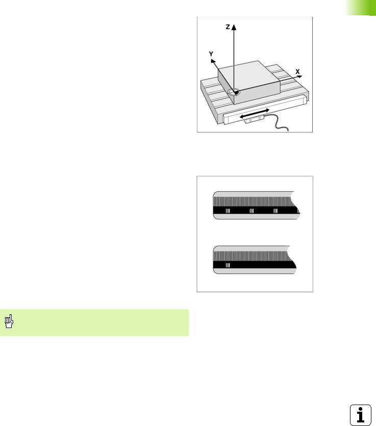
The position feedback encoders convert the movement of the machine axes into electrical signals. The POSITIP 880 constantly evaluates these signals and calculates the actual positions of the machine axes, which it displays as a numerical value on the screen. See Fig. I.9.
If there is an interruption in power, the calculated position will no longer correspond to the actual position. When power is restored, you can re-establish this relationship with the aid of the reference marks on the position encoders and the POSITIP 880's reference mark evaluation feature (REF).
Fig. I.9 Linear position encoder, here for the X axis
Reference Marks
The scales of the position encoders contain one or more reference marks. When reference marks are crossed they can be used to define an absolute position in an incremental system. If power is interrupted this absolute position is lost and the relationship between the reference mark and scale position is lost. The reference marks on the position encoders and the POSITIP 880's reference mark evaluation feature allows the unit to quickly re-establish this relationship again when power is restored. See Fig. I.10.
When a reference mark is crossed over, it generates a signal which identifies that position as the reference point. The POSITIP 880 uses this reference point to restore the relationship between the scale position and the display value which was last defined by setting the datum.
If the position encoders feature distance-coded reference marks, there are reference marks uniquely spaced along the length of the scale. Crossing any two reference marks will restore the datum. Each axis need only move a limited distance for linear encoders, and angle
for rotary encoders. Fig. I.10 Linear scales: with distance-coded reference marks (upper illustration) and one
reference mark (lower illustration)
The datum setting cannot be restored from one power cycle to the next if the reference marks were not crossed before the datum was set.
I – 1 Fundamentals of Positioning
POSITIP 880 |
17 |
I – 1 Fundamentals of Positioning
Angle Reference Axis
For angular positions, the following reference axes are defined: |
|
|
|
|
|
Plane |
Angle reference axis |
|
XY |
+X |
|
|
|
|
YZ |
+Y |
|
|
|
|
ZX |
+Z |
|
|
|
|
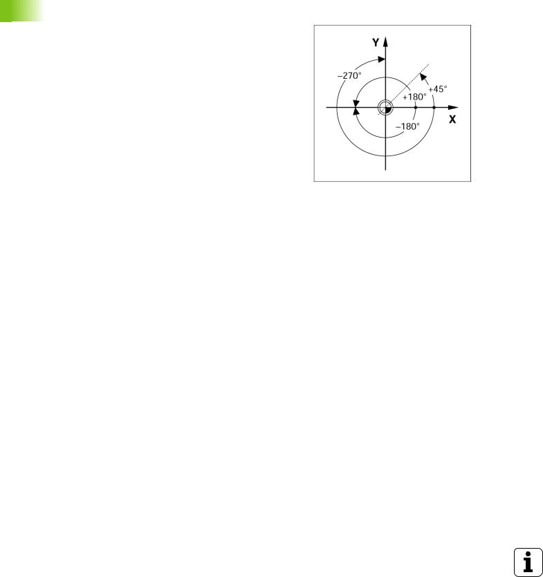
Positive direction of rotation is counterclockwise if the working plane |
|
|
is viewed in negative tool axis direction. See Fig. I.11. |
|
|
Example: Angle in the working plane X / Y |
|
|
|
|
|
Angle |
Corresponds to the... |
|
+ 45° |
... bisecting line between +X and +Y |
|
|
|
|
+/– 180° |
... negative X axis |
Fig. I.11 Angle and the angle reference axis, e.g. in |
|
|
|
- 270° |
... positive Y axis |
the X / Y plane |
|
||
|
|
|
18 |
I Operating Instructions |
I – 2 Working with POSITIP 880 –
First Steps
Power Up
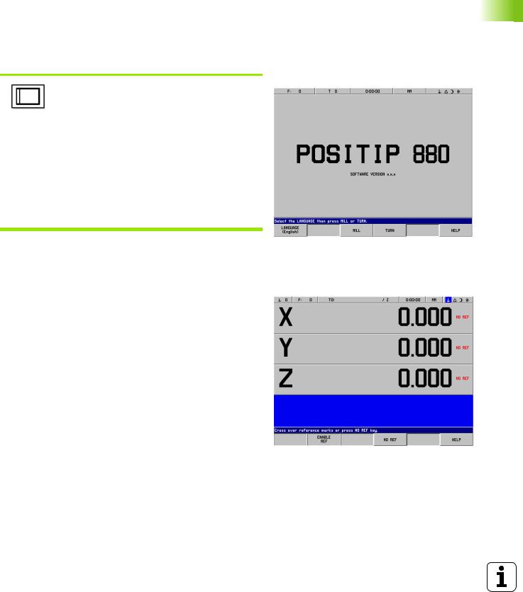
Switch on the power (located on the back). It will take approximately 25 - 30 seconds for system to start after power up. The initial screen will appear (This screen will only appear the first time you power up). Select the language by pressing the LANGUAGE soft key.
At this point you have the choice of MILL or TURN. Select the MILL soft key to proceed with milling functions the first time you power up. See Table of Contents for turning functions section. See Fig. I.12.
You can change the application later in
INSTALLATION SETUP under COUNTER SETTINGS.
Your POSITIP 880 is now ready for operation and is in the operating |
Fig. I.12 Initial screen |
mode ACTUAL VALUE. Axis will show “NO REF”. |
|
Before You Start
The POSITIP 880's reference mark evaluation feature automatically reestablishes the relationship between axis slide positions and display values that you last defined by setting the datum.
If the axis encoder has reference marks, the NO REF indicator will flash. See Fig. I.13. After crossing over the reference marks, the indicator will stop flashing and change to REF.
Working without reference mark evaluation
You can also use the POSITIP 880 without crossing over the reference marks. Press the NO REF soft key to exit the reference mark evaluation routine and continue in ACTUAL VALUE mode. The NO REF indicator will indicate that reference marks were not crossed over for that axis.
You can still cross over reference marks at a later time. The ENABLE REF soft key will be available from ACTUAL VALUE mode. Press this soft key to activate the reference mark evaluation routine.
Fig. I.13 Display before choosing NO REF
I – 2 Working with POSITIP 880 – First Steps
POSITIP 880 |
19 |

I – 2 Working with POSITIP 880 – First Steps
ENABLE REF function
The purpose of the ENABLE REF function, is to give the operator the opportunity to either ignore the reference marks as they are crossed over by disabling it, or finding reference marks when necessary by enabling it. When the ENABLE REF soft key is pressed, the POSITIP 880 is ready to identify a reference mark. When the ENABLE REF soft key is not depressed, POSITIP 880 will ignore all reference marks. When all reference marks have been found, the ENABLE REF soft key will disappear.
If an encoder is setup without reference marks, then the REF indicator will not be displayed.
Once reference marks for all desired axes are established, press NO REF soft key to cancel out of routine. You do not have to cross over the reference marks of all the encoders, only those that you need.
If you do not cross over the reference marks, POSITIP 880 does not store the datum points. This means that it is not possible to re-establish the relationship between axis slide positions and display values after a power interruption (switch-off).
Turn on power and press any key.
Cross over the reference marks (in any order).
Do not cross over the reference marks. Note: In this case the relationship between axis slide position and display value will be lost after a power interruption.
Press the NO REF soft key.
20 |
I Operating Instructions |
Operating Modes
Selecting the operating mode determines which functions are available to you.
Available functions |
Mode |
Key |
Position display for workpiece |
ACTUAL VALUE |
|
machining; Zero reset; Datum |
|
|
setting – also with edge finder probe |
|
|
|
|
|
Distance-to-go display; hole |
DISTANCE-TO-GO |
|
patterns; milling and drilling with tool |
|
|
radius compensation |
|
|
|
|
|
Storage of work steps for small-lot |
PROGRAMMING |
|
production |
|
|
|
|
|
Run programs previously created in |
EXECUTE PROGRAM |
|
the PROGRAMMING mode |
|
|
You can switch to another operating mode at any time by pressing the key for the desired mode.
In the following examples requiring tool usage, refer to chapter I-8 under Job Setup.
I – 2 Working with POSITIP 880 – First Steps
POSITIP 880 |
21 |

I – 2 Working with POSITIP 880 – First Steps
On-Screen Operating Instructions (HELP Mode)
The integrated operating instructions provide information and assistance in any situation. See Fig. I.14 & Fig. I.15.
To call the operating instructions:
8Press the INFO soft key.
8Press the HELP soft key.
8Information relevant to the current operation will be displayed.
8Use the paging soft keys if the explanation is spread over more than one screen page.
To view information on another topic:
8Press the LIST OF TOPICS soft key.
8Press the paging soft keys to scroll through the index.
8Press the VIEW TOPIC soft key to select the item you need.
To leave the operating instructions: |
Fig. I.14 Index under HELP mode |
8 Press the EXIT HELP soft key.
Example: On-screen operating instructions for datum setting with the edge finder (CENTER LINE)
The CENTER LINE function is described in this manual on page 20.
8From the ACTUAL VALUE mode, press the PROBE soft key.
8Press the INFO soft key.
8Press the HELP soft key.
8To leave the operating instructions: Press the EXIT HELP soft key. The screen returns to the screen with the SET DATUM form and DRO display.
Fig. I.15 On-screen operating instructions for datum setting
Confirming Your Changes
You must confirm your changes by pressing the ENT key for them to become effective. The instruction sections of this manual will occasionally give the command “Confirm your changes.” This means press the ENT key.
22 |
I Operating Instructions |

Messages
The Message bar messages will change color depending on the type of information it is conveying: Normal messages will appear as gray boxes with black text. Instructional messages will appear as blue boxes with white text. Error messages will appear as red boxes with white text.
Error messages
If an error occurs while you are working with POSITIP 880, the Message bar will turn red and provide an explanation of what caused the error.
To clear the error message:
8 Press the CE (Clear Entry) key.
Critical error messages
Critical error messages mean that the operational reliability of the POSITIP 880 has been impaired.
If a critical error occurs, a message box will appear in the middle of the screen:
8Take note of the error message displayed on the screen.
8Switch off the power to the POSITIP 880.
8Attempt to correct the problem with the power off.
8If the critical error message recurs, notify your customer service agency.
I – 2 Working with POSITIP 880 – First Steps
POSITIP 880 |
23 |

I – 2 Working with POSITIP 880 – First Steps
Selecting the Unit of Measure
Positions can be displayed and entered in millimeters or inches. If you choose inches, INCH will be displayed on the status bar at the top of the screen. See Fig. I.16.
To change the unit of measure:
8Press the INFO soft key.
8Press the INCH/MM soft key.
8The unit of measure can also be set in JOB SETUP. Refer to Job Setup, chapter I-8.
Fig. I.16 The MM indicator
Selecting the Angle Format
Angles – such as for a rotary table – can be displayed and entered either as decimal degrees, degrees/minutes/seconds (DMS) or radian values. Refer to Job Setup, chapter I-8 for instructions on setting angle format.
Tool Table
The POSITIP 880’s tool table provides a convenient way to store diameter and length offset information for each of the tools you commonly use. You can enter up to 99 tools.
Before you start workpiece machining, select the tool you are using from the tool table. POSITIP 880 will then take into account the entered diameter and length of the tool.
The tool length is the difference in length L between the tool and the reference tool. The reference tool is indicated by T1 in Fig. I.17.
Sign for the length difference L
If the tool is longer than the reference tool: L > 0 (+)
If the tool is shorter than the reference tool: L < 0 (–)
Refer to Job Setup for entering a tool into the tool table.
Fig. I.17 Tool length and diameter
24 |
I Operating Instructions |

Calling the Tool Data
The lengths and diameters of your tools must first be entered into the POSITIP 880's tool table.
Before you start machining, select the tool you are using from the tool table. POSITIP 880 then takes into account the stored tool data when you work with tool compensation (e.g., with hole patterns).
You can also call the tool data with the command TOOL CALL in a program.
Tool call
Press the INFO soft key.
Then the JOB SETUP soft key. (Tool table is highlighted).
Press ENT.
TOOL NUMBER
Cursor to the tool you want or enter the tool number directly.
Press USE, then USE NEW SETTINGS.
View status bar to verify the proper tool has been called.
I – 2 Working with POSITIP 880 – First Steps
POSITIP 880 |
25 |

I – 3 Actual Value
I – 3 Actual Value
Datum Setting: Approaching Positions and
Entering Actual Values
The easiest way to set datum points is to use the POSITIP 880's probing functions – regardless of whether you probe the workpiece with the HEIDENHAIN KT Edge Finder or with a tool. Description of the probing functions: See "Probing Functions for Datum Setting" on page 28
Of course, you can also set datum points in the conventional manner by touching the edges of the workpiece one after the other with the tool and entering the tool positions as datum points (see examples following this page).
The datum table can hold up to 99 datum points. In most cases this will free you from having to calculate the axis travel when working with complicated workpiece drawings containing several datums.
Datum settings are performed in the ACTUAL VALUE operating mode and define the relationships between the axis positions and the display values. If necessary, the datum table’s values may be changed by entering a value directly.
See Job Setup for setting the datum value directly.
Datum selection (Mill only)
In ACTUAL VALUE mode, the Up/Down arrow keys may be used to select the next or previous datum number.
Tool selection (Turn only)
In ACTUAL VALUE mode, the Up/Down arrow keys may be used to select the next or previous tool number.
26 |
I Operating Instructions |

Example: Setting a workpiece datum without the probing function. See Fig. I.18 & Fig. I.19.
Working plane: XY Tool axis: Z
Tool diameter: D = 3 mm
Axis sequence in this example: X - Y - Z
Preparation: Calling the tool data
Select the tool data for the tool which you are using to touch the workpiece.
Preparation: Select the datum
Operating mode: ACTUAL VALUE
From ACTUAL VALUE mode, press the DATUM soft key.
Cursor will be in the DATUM NUMBER field.
Enter the datum number and press ENT.
Touch the workpiece at edge 1.
Select the X axis key.
DATUM SETTING X
Enter the position of the tool center (X = – 1.5 mm) and
transfer the X-coordinate of the datum and press ENT.
Touch the workpiece at edge 2.
Select the Y axis key.
Fig. I.18 SET DATUM form
Fig. I.19
I – 3 Actual Value
POSITIP 880 |
27 |

I – 3 Actual Value
DATUM SETTING Y
Enter the position of the tool center (Y = – 1.5 mm) and
transfer the Y-coordinate of the datum and press ENT.
Touch the workpiece surface.
Select the Z axis key.
DATUM SETTING Z = + 0
Enter the position of the tool tip (Z = 0 mm) and transfer the Z-coordinate of the datum. Press USE.
Probing Functions for Datum Setting
It is particularly easy with a HEIDENHAIN KT 130 Edge Finder (Fig.
I.20).
During probe functions, the display freezes with the location of the edge, centerline, or circle center.
The following probing soft key functions are available:
Workpiece edge as datum: EDGE
Centerline between two workpiece edges: CENTER LINE
Center of a hole or cylinder: CIRCLE CENTER
With Circle Center, the hole must be in a main plane. The three main planes are formed by the axes X / Y, Y / Z and Z / X.
The POSITIP 880's probing functions enable you to set datum points with a HEIDENHAIN KT Edge Finder. The probing functions are also available when you are using a tool instead of an edge finder.
Fig. I.20 The HEIDENHAIN KT 130 Edge Finder
28 |
I Operating Instructions |

Datum setting with the edge finder
Preparation: Enter the stylus diameter and select the datum
8Press the INFO soft key.
8Press JOB SETUP, then cursor to EDGE FINDER and press ENT.
8Enter the diameter of the edge finder stylus and confirm with ENT.
8Enter the desired length and confirm with ENT.
8Enter the desired unit of measurement (inch/mm).
8Press USE, then USE NEW SETTINGS.
In all probing functions, POSITIP 880 takes into account the entered stylus diameter.
To abort the probing function
While the probing function is active, POSITIP 880 displays the CANCEL soft key. Choose this soft key to return to the opening state of the selected probing function.
I – 3 Actual Value
POSITIP 880 |
29 |

I – 3 Actual Value
Example: Probe workpiece edges, and set the corner as a datum.
See Fig. I.21 & Fig. I.22.
Datum axis: |
X = 0 mm |
|
Y = 0 mm |
The coordinates of the datum can be set by probing edges or surfaces and capturing them as datums as described on the next page.
Operating mode: ACTUAL VALUE
Press the PROBE soft key.
Cursor to axis.
Press EDGE soft key.
Fig. I.21 Form for setting datum using an edge
PROBE IN X AXIS
Move the edge finder toward the workpiece until the
LEDs on the edge finder light up.
Retract the edge finder from the workpiece.
ENTER VALUE FOR X + 0
0 is offered as a default value for the coordinate. Enter the desired coordinate for the workpiece edge, for example X = 0 mm and
set the coordinate as a datum for this workpiece
edge. Press ENT.
Fig. I.22
Press EDGE soft key.
PROBE IN Y AXIS
Move the edge finder toward the workpiece until the
LEDs on the edge finder light up.
Retract the edge finder from the workpiece.
30 |
I Operating Instructions |
Loading...