


Pilot
TNC 310
NC-Software 286 040-xx
6/2000

The Pilot
... is your concise programming guide for the HEIDENHAIN TNC 310 contouring control. For more comprehensive information on programming and operating, refer to the TNC User's Manual. There you will find complete information on the central tool file.
Certain symbols are used in the Pilot to denote specific types of information:
Important note
 Warning: danger for the user or the machine.
The TNC and the machine tool must be prepared by the machine tool builder to perform these functions.
Chapter in User's Manual where you will find more detailed information on the current topic.
This Pilot describes the operation of the TNC 310 as of the following software number:
Control |
NC Software Number |
TNC 310 |
286 040 xx |
|
|
Contents |
|
Fundamentals ................................................................... |
4 |
Contour Approach and Departure ..................................... |
13 |
Path Functions .................................................................. |
14 |
Subprograms and Program Section Repeats .................... |
21 |
Working with Cycles ......................................................... |
24 |
Drilling Cycles ................................................................... |
26 |
Pockets, Studs, and Slots ................................................. |
33 |
Point Patterns ................................................................... |
42 |
Multipass Milling ............................................................... |
44 |
Coordinate Transformation Cycles .................................... |
46 |
Special Cycles ................................................................... |
50 |
Graphics and Status Displays ............................................ |
52 |
Miscellaneous Functions M .............................................. |
54 |
Contents
3

Fundamentals
4
Fundamentals
Programs/Tables
Programs and tables are stored in the TNC as files. The file name is composed of two parts:
3546351.H
File name |
File type |
Maximum length: |
see table at right |
8 characters |
|
|
|
Creating a New Part Program
 Enter a new file name
Initiate a conversational program.
 Select unit of measure for dimensions (mm or inches)
 Define the blank form (BLK) for graphics:
Enter the spindle axis
Enter coordinates of the MIN point: the smallest X, Y and Z coordinates
Enter coordinates of the MAX point: the greatest X, Y and Z coordinates
1 BLK FORM 0.1 Z X+0 Y+0 Z-50
2 BLK FORM 0.2 X+100 Y+100 Z+0
Files in the TNC |
File type |
|||
Programs in |
|
|
||
• HEIDENHAIN format |
.H |
|||
|
|
|
||
Tables for |
|
|
||
• Tools |
TOOL.T |
|||
|
|
|
|
|
|
|
|
|
|
|
|
|
|
|
|
|
|
|
|
|
|
|
|
|
|
|
|
|
|

Choosing the screen layout

 See Chapter 1, “Introduction” in the User’s Manual.
 Show soft keys for setting the screen layout
Mode of operation |
Options |
|
|
PROGRAM RUN, FULL SEQ. PROGRAM RUN, SINGLE BLOCK TEST RUN
Program
Program at left
Program information at right
Program at left
Additional position display at right
Program at left
Tool information at right
Program at left
Active coordinate transformations at right
 Program at left, tool information at right
Continued on next page 
Fundamentals
5

Fundamentals
6
Mode of operation |
Options |
|
|
PROGRAMMING AND EDITING |
Program |
|
|
|
|
|
|
|
Programming graphics |
|
|
|
|
|
|
|
Program at left |
|
|
|
Programming graphics right |
|
|
|
|
|
|
|
Program at left |
|
|
|
Graphics illustrating input |
|
|
|
parameters at right |
|
|
|
|
|
|
|
|
|
|
You cannot change the screen layout in the MANUAL and |
|
Program at left, graphic support at right |
|
POSITIONING WITH MDI modes. |
|
|
|
|
|
|
|

Absolute Cartesian Coordinates
The dimensions are measured from the current datum. The tool moves to the absolute coordinates.
Programmable axes in an NC block
Linear motion: any 3 axes
Circular motion: 2 linear axes in a plane
Incremental Cartesian Coordinates
The dimensions are measured from the last programmed position of the tool.
The tool moves by the incremental coordinates.
Fundamentals
7

Fundamentals
8
Circle Center and Pole: CC
The circle center (CC) must be entered to program circular tool movements with the path function C (see page 17). CC is also needed to define the pole for polar coordinates.
CC is entered in Cartesian coordinates*.
An absolutely defined circle center or pole is always measured from the workpiece datum.
An incrementally defined circle center or pole is always measured from the last programmed position of the workpiece.
Angle Reference Axis
Angles – such as a polar coordinate angle PA or an angle of rotation
ROT – are measured from the angle reference axis.
Working plane |
Ref. axis and 0° direction |
|
|
|
X/Y |
X |
|
|
|
Y/Z |
Y |
|
|
|
Z/X |
Z |
|
|
|
|
|
|
|
|
|
|
|
|
|
|
|
|
|
|
*Circle center in polar coordinates: See FK programming
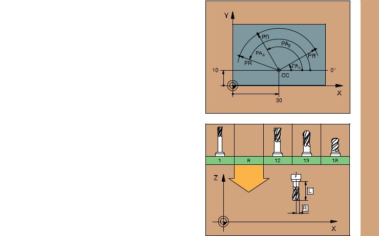
Polar Coordinates
Dimensions in polar coordinates are referenced to the pole (CC). A position in the working plane is defined by
•Polar coordinate radius PR = Distance of the position from the pole
•Polar coordinate angle PA = Angle from the angle reference axis to the straight line CC – PR
Incremental dimensions
Incremental dimensions in polar coordinates are measured from the last programmed position.
Programming polar coordinates
 Select the path function
 Press the P key
 Answer the dialog prompts
Defining Tools
Tool data
Every tool is designated by a tool number between 1 and 254.
Entering tool data
You can enter the tool data (length L and radius R) either:
•centrally in a table (tool file TOOL.T) for common use by all programs
or
•locally in TOOL DEF blocks within each part program
Fundamentals
9

Fundamentals
10
 TOOL NUMBER
 TOOL LENGTH L
 TOOL RADIUS R
 Program the tool length as its difference ∆L to the zero tool:
∆L>0: The tool is longer than the zero tool ∆L<0: The tool is shorter than the zero tool
 With a tool presetter you can measure the actual tool length, then program that length.
Calling the tool data
 TOOL NUMBER
 WORKING SPINDLE AXIS: tool axis
 SPINDLE SPEED S
 OVERSIZE for the TOOL LENGTH DL (e.g. for wear)
  OVERSIZE for the TOOL RADIUS DR (e.g. for wear)
3 |
TOOL |
DEF 6 |
L+7.5 R+3 |
|
4 |
TOOL |
CALL 6 |
Z S2000 DL+1 DR+0.5 |
|
5 |
L |
Z+100 R0 |
FMAX |
|
6 |
L |
X-10 Y-10 |
R0 FMAX M6 |
|
Tool change
• Beware of tool collision when moving to the tool change position.
•The direction of spindle rotation is defined by M function: M3: Clockwise
M4: Counterclockwise
•Oversizes for tool length or radius cannot exceed ±99.999 mm!
 Oversizes on an end mill
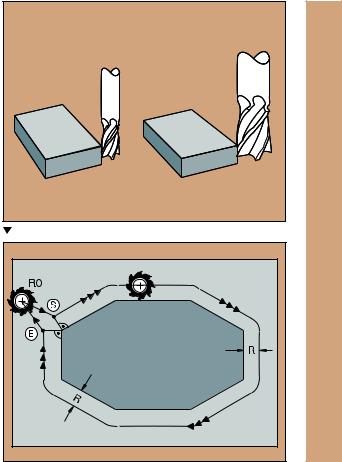
Tool Compensation
The TNC compensates the length L and radius R of the tool during machining.
Length compensation
Beginning of effect:
 Tool movement in the spindle axis
End of effect:
 Tool exchange or tool with the length L=0
Radius compensation Beginning of effect:
 Tool movement in the working plane with RR or RL
End of effect:
 Execution of a positioning block with R0
Working without radius compensation (e.g. drilling):  Tool movement with R0
S= Start; E= End |
Fundamentals
11
Fundamentals
12
Datum Setting Without a 3D Touch Probe
During datum setting you set the TNC display to the coordinates of a known position on the workpiece:
 Insert a zero tool with known radius
Select the MANUAL OPERATION or ELECTRONIC HANDWHEEL mode
Touch the reference surface in the tool axis with the tool and enter its length
Touch the reference surface in the working plane with the tool and enter the position of the tool center
Datum Setting with a 3D Touch Probe
The fastest, simplest and most accurate way to set a datum is to use a HEIDENHAIN 3D touch probe.
The following probe functions are provided by the MANUAL OPERATION and ELECTRONIC HANDWHEEL modes of operation:
Basic rotation
Datum setting in one axis
Datum setting at a corner
Datum setting at a circle center

Contour Approach and Departure
Smooth approach
 ROUNDING RADIUS R for approaching arc
  FEED RATE for approaching arc
Program an RND black after the first contour point, i.e. after the first block with radius compensation RL/RR.
7 L X+5 Y+5 R0 FMAX M3
8 L X+15 Y+15 RL F125
9 RND R10 F75
Smooth departure
 ROUNDING RADIUS R for departing arc
  FEED RATE for departing arc
Program an RND block after the last contour point, i.e. after the last block with radius compensation RL/RR.
25 L X+15 Y+15 RL F125
26 RND R10 F75
27 L X+5 Y+5 R10 F1000
Contour Approach and Departure
13

Path Functions
Path Functions for Positioning Blocks

 See “Programming: programming contours”
Programming the Direction of Traverse
Regardless of whether the tool or the workpiece is actually moving, you always program as if the tool is moving and the workpiece is stationary.
Entering the Target Positions
Target positions can be entered in Cartesian or polar coordinates – either as absolute or incremental values, or with both absolute and incremental values in the same block.
Entries in the Positioning Block
A complete positioning block contains the following data:
•Path function
•Coordinates of the contour element end points (target position)
•Radius compensation RR/RL/R0
•Feed rate F
•Miscellaneous function M
Before you execute a part program, always pre-position the tool to prevent the possibility of damaging the tool or workpiece.
Path Functions
Straight line |
Page 15 |
||
Chamfer between two |
Page 16 |
||
straight lines |
|||
|
|
||
Corner rounding |
Page 16 |
||
Circle center or pole for |
Page 17 |
||
polar coordinates |
|||
|
|
||
Circular patharound the |
Page 17 |
||
circle center CC |
|||
|
|
||
Circular path with |
Page 18 |
||
known radius |
|||
|
|
||
Circular path with |
Page 19 |
||
tangential connection |
|||
to previous contour |
|
|
|
|
|
|
|
14

Straight Line
 COORDINATES of the straight line end point
 TOOL RADIUS COMPENSATION RR/RL/R0
 FEED RATE F
  MISCELLANEOUS FUNCTION M
With Cartesian coordinates:
7 L X+10 Y+40 RL F200 M3
8 L IX+20 IY-15
9 L X+60 IY-10
With polar coordinates:
12 CC X+45 Y+25
13 LP PR+30 PA+0 RR F300 M3
14 LP PA+60
15 LP IPA+60
16 LP PA+180
• You must first define the pole (CC) before you can program polar coordinates.
•Program the pole only in Cartesian coordinates!
•The pole remains effective until you define a new one.
Path Functions |
15 |

Path Functions
Inserting a Chamfer Between Two Straight Lines
 CHAMFER SIDE LENGTH
7 L X+0 Y+30 RL F300 M3
8 L X+40 IY+5
9 CHF 12
10 L IX+5 Y+0
• You cannot start a contour with a CHF block.
• The radius compensation before and after the CHF block must be the same.
•An inside chamfer must be large enough to accommodate the current tool.
Corner Rounding
The beginning and end of the arc extend tangentially from the previous and subsequent contour elements.
 RADIUS R of the circular arc
 FEED RATE F for corner rounding
5 L X+10 Y+40 RL F300 M3
6 L X+40 Y+25
7 RND R5 F100
8 L X+10 Y+5
16 |
An inside arc must be large enough to accommodate the |
current tool. |

Circular Path Around the Circle Center CC
 COORDINATES of the circle center CC
 COORDINATES of the arc end point
 DIRECTION OF ROTATION DR
C and CP enable you to program a complete circle in one block.
With Cartesian coordinates:
5 |
CC X+25 Y+25 |
|
|
|
|
6 |
L X+45 |
Y+25 |
RR |
F200 M3 |
|
7 |
C X+45 |
Y+25 |
DR+ |
|
|
With polar coordinates: |
|
|
|||
|
|
|
|
||
18 |
CC X+25 Y+25 |
|
|
||
19 |
LP PR+20 PA+0 |
RR F250 |
M3 |
||
20 |
CP PA+180 DR+ |
|
|
||
• Define the pole (CC) before programming polar coordinates.
• Program the pole only in Cartesian coordinates.
•The pole remains effective until you define a new one.
•The arc end point can be defined only with the polar coordinate angle (PA).
Path Functions
17

Path Functions
Circular Path with Known Radius (CR)
 COORDINATES of the arc end point
 RADIUS R
If the central angle ZW > 180, R is negative. If the central angle ZW < 180, R is positive.  DIRECTION OF ROTATION DR
10 |
L X+40 Y+40 RL F200 M3 |
Arc starting point |
||||
11 |
CR |
X+70 |
Y+40 |
R+20 |
DR- |
Arc 1 or |
11 |
CR |
X+70 |
Y+40 |
R+20 |
DR+ |
Arc 2 |
10 |
L X+40 Y+40 RL F200 M3 |
Arc starting point |
||||
11 |
CR |
X+70 |
Y+40 |
R-20 |
DR- |
Arc 3 or |
11 |
CR |
X+70 |
Y+40 |
R-20 |
DR+ |
Arc 4 |
|
|
|
|
|
|
|
|
|
|
|
|
|
|
|
|
|
|
|
|
|
|
|
|
|
|
|
|
|
|
|
|
|
|
|
|
|
|
|
|
|
|
|
|
|
|
|
|
|
|
|
|
|
|
|
|
|
|
|
|
|
|
|
|
|
|
|
|
|
|
|
|
|
|
|
|
|
|
|
|
|
|
|
|
|
|
|
|
|
|
|
|
|
|
|
|
|
|
|
|
|
|
|
|
|
|
|
|
|
|
|
|
|
|
|
|
|
|
|
|
|
|
|
|
|
|
|
|
|
|
|
|
|
|
|
|
|
|
|
|
|
|
|
|
|
|
|
|
|
|
|
|
|
|
|
|
|
|
|
|
|
|
|
|
|
|
|
|
|
|
|
|
|
|
|
|
|
|
|
|
|
|
|
|
|
|
|
|
|
|
|
|
Arcs 1 and 2 |
|
|
|
|
Arcs 3and 4 |
||||||||||
|
|
|
|
|
|
|
|
|
|
|
|
|
|
|
|
|
|
|
|
|
|
|
|
|
|
|
|
|
|
|
|
|
|
|
|
|
|
|
|
|
|
|
|
|
|
|
|
|
|
|
|
|
|
|
|
|
|
|
|
|
|
|
|
|
|
|
|
|
|
|
|
|
|
|
|
|
|
|
|
|
|
|
|
|
|
|
|
|
|
|
|
|
|
|
|
|
|
|
|
|
|
|
|
|
|
|
|
|
|
|
|
|
|
|
|
|
|
|
|
|
|
|
|
|
|
|
|
|
|
|
|
|
|
|
|
|
|
|
|
|
|
|
|
18
 Loading...