


User’s Manual
Position Display Units for Lathes
6/99

Position display |
• Select coordinate axis |
(ND 730 only two axes) |
(ND 730 only X and Z) |
|
• Select axis-based operating parameters |
Status display: |
Numerical input |
SET = Set datum REF = Blinking:
Traverse reference marks
Lighting:
Reference marks have been traversed
∆ = Distance-to-go
Inch= Inch display
SCL = Scaling factor
R= Radius/diameter display
T = Tool selected
HEIDENHAIN
•Change sign
•Call last dialog
•In parameter list: Change parameter
•Confirm entry
•Scroll forwards in parameter list
Select radius/diameter display in X axis
•Select special functions
•Scroll forwards in special functions list
•Tool compensation
•Scroll backwards in special functions list
•Scroll backwards in parameter list
•Abort entry
•Reset operating mode
•Reset selected axis to zero (if activated via P 80)
•Select parameter:
CL plus two-digit number

This manual is for ND display units with the following software numbers or higher:
ND 730 for two axes |
AA00 |
ND 770 for three axes |
AA00 |
About this manual!
This manual is divided into two parts:
Part I: Operating Instructions:
•Fundamentals of positioning
•ND functions
Part II: Installation and Specifications:
•Mounting the display unit on the machine
•Description of operating parameters
Part I Operating Instructions
Fundamentals |
4 |
Switch-On, Reference-Mark Traverse |
10 |
|
|
Selecting Radius or Diameter Display |
11 |
|
|
Separate Value/Sum Display |
|
(only ND 770) |
12 |
|
|
Datum Setting |
13 |
Setting the absolute workpiece datum |
13 |
Entering tool data (relative datums) |
14 |
|
|
Holding Positions |
15 |
|
|
Moving the Axes with Distance-To-Go |
17 |
|
|
Taper Calculator |
19 |
|
|
Error Messages |
23 |
|
|
Part II |
|
Installation and Specifications |
25 |
Part I Operating Instructions
3
Fundamentals
4
Fundamentals
You can skip this chapter if you are already familiar with coordinate systems, incremental and absolute dimensions, nominal positions, actual positions and distance-to-go!
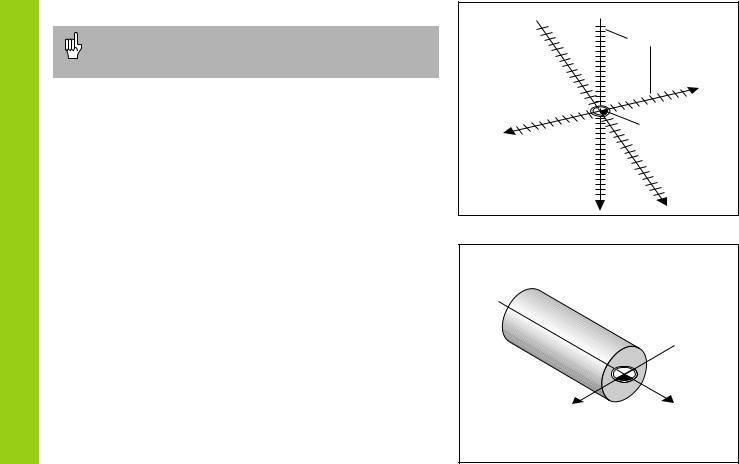
Coordinate system
To describe the geometry of a workpiece, a rectangular or Cartesian1) coordinate system is used. The Cartesian coordinate system consists of three mutually perpendicular axes X, Y and Z. The point of intersection of these axes is called the datum or origin of the coordinate system.
Think of the axes as scales with divisions (usually in millimeters) that allow us to fix points in space referenced to the datum.
To determine positions on a workpiece, the coordinate system is “laid” onto the workpiece.
With lathe work (i.e. rotationally symmetrical workpieces), the Z axis moves along the axis of rotation, and the X axis moves in the direction of the radius or diameter. The Y axis can be disregarded since it would always have the same values as the X axis.
1)Named in honor of the French mathematician and philosopher René Descartes (1596 to 1650)
+Y  +Z
+Z
Graduation
+X
–X |
Datum or |
|
origin |
–Z |
–Y |
|
X |
Z |
|
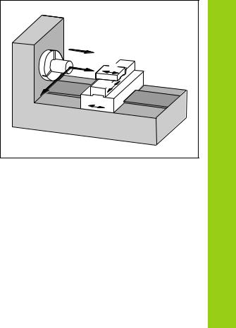
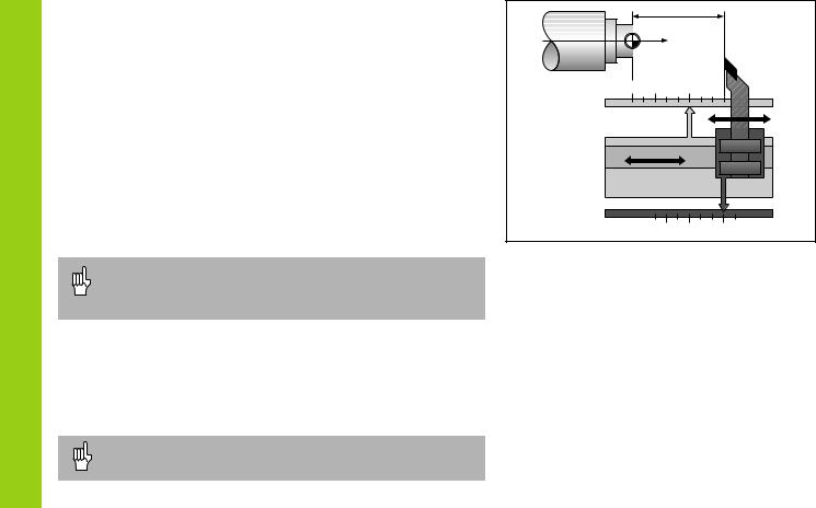
Cross slide, saddle and top slide
On conventional lathes, the tool is mounted on a slide that moves in the direction of the X axis (the cross slide) and in the direction of the Z axis (the saddle).
Most lathes have a top slide above the saddle. The top slide moves in Z axis direction and is designated Zo.
+ZO |
|
Fundamentals |
+Z |
ZO |
|
|
||
|
X |
|
|
|
|
|
Z |
|
5
Fundamentals
Datum setting
The workpiece drawing is used as the basis for machining the workpiece. To enable the dimensions in the drawing to be converted into traverse distances of machine axes X and Z, each drawing dimension requires a datum or reference point on the workpiece (since a position can only be defined in relationship to another position).
The workpiece drawing always indicates one absolute datum (the datum for absolute dimensions). However, it may contain additional, relative datums.
In the context of a numerical position display unit, datum setting means bringing the workpiece and the tool into a defined position in relation to each other and then setting the axis displays to the value which corresponds to that position. This establishes a fixed relationship between the actual positions of the axes and the displayed positions.
With the ND, you can set one absolute datum point and as many as 9 relative datum points (tool datums), and store them in nonvolatile memory.
30 |
35 |
|
|
|
Absolute |
|
|
datum |
|
|
Z |
|
|
5 |
|
|
10 |
|
Relative |
X |
|
datum |
|
6
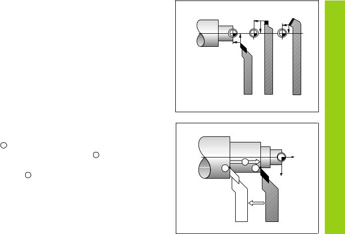
Tool datums (tool compensation)
Your display unit should show you the absolute position of the workpiece, regardless of the length and shape of the particular tool being used. For this reason you must determine the tool data and enter it. First touch the workpiece with the cutting edge of the tool and then enter the associated display value for that position.
You can enter tool data for up to 9 tools. When you have set the absolute workpiece datum for a new workpiece, all tool data (= relative datum points) are referenced to the new workpiece datum.
Nominal position, actual position and distance-to-go
The positions to which the tool is to move are called the nominal
positions ( S ). The position at which the tool is actually located at any
given moment is called the actual position ( I ).
The distance from the nominal position to the actual position is called
the distance-to-go ( R ).
Sign for distance-to-go
When you are using the distance-to-go display, the nominal position becomes the relative datum (display value 0). The distance-to-go is therefore negative when you move in the positive axis direction, and positive when you move in the negative axis direction.
|
|
Fundamentals |
T1 |
T2 |
T3 |
|
Z |
|
R |
S |
I |
|
X |
7

Fundamentals
8
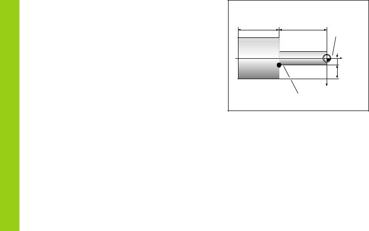
Absolute workpiece positions
Each position on the workpiece is uniquely defined by its absolute coordinates.
Example |
Absolute coordinates of position 1 : |
|
|
X = |
5 mm |
|
Z = |
–35 mm |
If you are working according to a workpiece drawing with absolute dimensions, you are moving the tool to the coordinates.
Relative workpiece positions
A position can also be defined relative to the previous nominal position. The datum for the dimension is then located at the previous nominal position. Such coordinates are termed relative coordinates or chain dimensions. Incremental coordinates are indicated by a preceding I.
Example Relative coordinate of position 2 referenced to position 1 :
IX = 10 mm IZ = –30 mm
If you are working according to a workpiece drawing with incremental dimensions, you are moving the tool by the dimensions.
Sign for incremental dimensioning
A relative dimension has a positive sign when the axis is moved in the positive direction, and a negative sign when it is moved in the negative direction.
65 |
35 |
0 |
|
|
Z |
|
|
5 |
|
|
1 |
|
|
15 |
|
|
X |
30 |
35 |
|
Z |
|
5 |
|
1 |
|
10 |
2 |
X |
|

Position encoders
The position encoders on the machine convert the movements of the machine axes into electrical signals. The ND display unit evaluates these signals, determines the actual position of the machine axes and displays the position as a numerical value.
If the power is interrupted, the relationship between the machine axis positions and the calculated actual positions is lost. The reference marks on the position encoders and the REF reference mark evaluation feature enable the ND to quickly re-establish this relationship again when the power is restored.
Reference marks
The scales of the position encoders contain one or more reference marks. When a reference mark is crossed over, a signal is generated identifying that position as a reference point (scale datum = machine datum).
When this reference mark is crossed over, the ND's reference mark evaluation feature restores the relationship between axis slide positions and display values as you last defined it by setting the datum. If the linear encoders have distance-coded reference marks, you need only move the machine axes a maximum of 20 mm to restore the datum.
|
Z |
Fundamentals |
|
|
|
Workpiece |
|
|
|
|
Encoder |
|
|
|
|
|
|
|
|
|
|
|
|
|
|
|
|
|
|
|
|
|
|
|
|
|
|
|
|
|
|
|
|
|
|
|
|
|
|
|
|
|
|
|
|
|
|
|
|
|
|
|
|
|
|
|
|
|
|
|
|
|
|
|
|
|
|
|
|
|
|
|
|
|
|
|
|
|
|
Scale in linear |
|
|
|
Distance-coded |
||||||||
encoder |
|
|
reference marks |
|||||||||
|
|
9 |
|
Reference mark |
|||
|
|||
Switch-On, Reference-Mark Traverse
Switch-On, Reference-Mark Traverse
0 è 1
ENT ... CL
ENT
Turn on the power (switch located on rear panel). REF is blinking in the status display.
Confirm reference-point traverse.
REF is now lighting. Decimal points are blinking.
Cross over the reference marks in all axes (in any sequence). Each axis display becomes active when its reference mark is crossed over.
Crossing over the reference marks stores the last relationship between axis slide positions and display values for all datum points in nonvolatile memory.
Note that if you choose not to cross over the reference marks (by clearing the dialog ENT ... CL with the CL key), this relationship will be lost if the power is switched off or otherwise interrupted!
You must cross over the reference marks if you want to use the multipoint axis error compensation function.
(See “Multipoint Axis Error Compensation”)
10
Selecting Radius or Diameter Display
Your ND can display positions in the cross slide as a diameter or as a radius. Drawings of lathe parts usually indicate diameters. When you are turning the part, however, you infeed the tool in the cross slide axis in radius values.
Example: |
Radius display position Q |
X |
= |
20 mm |
|
Diameter display position Q |
X |
= |
40 mm |
To switch the display:
¬ Press
When radius display for the X axis is selected, RX lights up. When diameter display is selected, RX goes out.
|
|
Z |
Display |
¯40 |
|
Diameter |
|
|
|
||
1 |
|
20 |
|
|
|
|
|
|
X |
|
|
|
|
|
Selecting Radius or |
11
Separate Value/Sum Display (ND 770 only)
Separate Value/Sum Display (ND 970 only)
Separate value display
In this mode the positions of the saddle and top slide are displayed separately. The position displays are referenced to the datum points that you set for the Zo and Z axes. When an axis slide moves, only the position display for that axis changes.
Sum display
In this mode the position values of both axis slides are added together. The sum display shows the absolute position of the tool, referenced to the workpiece datum.
Example |
Separate value display: |
Z |
= |
+25.000 mm |
|
|
Zo = |
+15.000 mm |
|
|
Sum display: |
ZS |
= |
+40.000 mm |
The sum display will only show correct values if the actual position values of both axis slides were correctly added and entered (with sign) when setting the datum for the “sum.”
To switch the display
Sum display: Press the keys Zo and Z at the same time.
Separate value display: Press the key Zo.
When the ND 770 displays sums, the Zo display is switched off.
|
40 |
|
|
|
Z |
|
|
0 |
+10 |
+25 |
|
Z |
|
|
Z0 |
|
|
|
|
|
Z |
|
|
Z0 |
Ð10 |
0 |
+15 |
|
|||
12
 Loading...