


 Loading...
TNC 410 TNC 426 TNC 430
NC Software 286 060-xx 286 080-xx 280 476-xx 280 477-xx
User’s Manual
ISO Programming
English (en)
8/2002
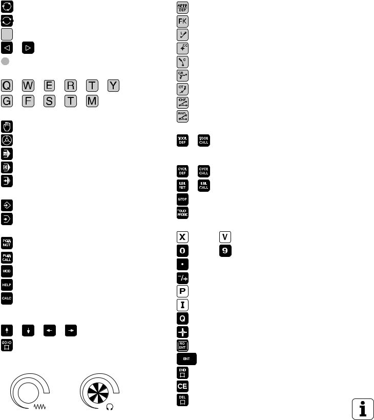
Controls on the visual display unit
Split screen layout
Switch between machining or programming modes
Soft keys for selecting functions in screen
Switching the soft-key rows
Changing the screen settings (only BC 120)
Typewriter keyboard for entering letters and symbols
File names Comments
ISO programs
Machine operating modes
MANUAL OPERATION
ELECTRONIC HANDWHEEL
POSITIONING WITH MDI
PROGRAM RUN, SINGLE BLOCK
PROGRAM RUN, FULL SEQUENCE
Programming modes
PROGRAMMING AND EDITING
TEST RUN
Program/file management, TNC functions
Select or delete programs and files External data transfer
Enter program call in a program
MOD functions
Display help texts for NC error messages
Pocket calculator
Moving the highlight, going directly to blocks, cycles and parameter functions
Move highlight
Go directly to blocks, cycles and parameter
functions
Override control knobs for feed rate/spindle speed
|
100 |
|
100 |
50 |
150 |
50 |
150 |
|
F % |
|
S % |
|
0 |
|
0 |
Programming path movements
Approach/depart contour
FK free contour programming
Straight line
Circle center/pole for polar coordinates
Circular arc with center
Circular arc with radius
Circular arc with tangential connection
Chamfer
Corner rounding
Tool functions
Enter and call tool length and radius
Cycles, subprograms and program section repeats
Define and call cycles
Enter and call labels for subprogramming and program section repeats
Program stop in a program
Enter touch probe functions in a program
Coordinate axes and numbers: Entering and editing
Select coordinate axes or
. . . enter them into the program
. . . Numbers
Decimal point
Change arithmetic sign
Polar coordinates
Incremental dimensions
Q parameters
Capture actual position
Skip dialog questions, delete words
Confirm entry and resume dialog
End block
Clear numerical entry or TNC error or delete error message
Abort dialog, delete program section


TNC models, software and features
This manual describes functions and features provided by the TNCs as of the following NC software numbers.
TNC model |
NC software no. |
TNC 426 CB, TNC 426 PB |
280 476-xx |
|
|
TNC 426 CF, TNC 426 PF |
280 477-xx |
|
|
TNC 426 M |
280 476-xx |
|
|
TNC 426 ME |
280 477-xx |
|
|
TNC 430 CA, TNC 430 PA |
280 476-xx |
|
|
TNC 430 CE, TNC 430 PE |
280 477-xx |
|
|
TNC 430 M |
280 476-xx |
|
|
TNC 430 ME |
280 477-xx |
|
|
TNC 410 |
286 060-xx |
|
|
TNC 410 |
286 080-xx |
|
|
The suffixes E and F indicate the export versions of the TNC The export versions of the TNC have the following limitations:
Linear movement is possible in no more than 4 axes simultaneously.
The machine tool builder adapts the useable features of the TNC to his machine by setting machine parameters. Some of the functions described in this manual may not be among the features provided by your machine tool.
TNC functions that may not be available on your machine include:
Probing function for the 3-D touch probe
Digitizing option
Tool measurement with the TT 130
Rigid tapping
Returning to the contour after an interruption
Please contact your machine tool builder to become familiar with the features of your machine.
Many machine manufacturers, as well as HEIDENHAIN, offer programming courses for the TNCs. We recommend these courses as an effective way of improving your programming skill and sharing information and ideas with other TNC users.
Touch Probe Cycles User's Manual:
All of the touch probe functions are described in a separate manual. Please contact HEIDENHAIN if you require a copy of this User's Manual. ID number: 329 203-xx.
HEIDENHAIN TNC 410, TNC 426, TNC 430 |
I |

Location of use
The TNC complies with the limits for a Class A device in accordance with the specifications in EN 55022, and is intended for use primarily in industrially-zoned areas.
New features of the NC software 280 476-xx
Thread milling cycles 262 to 267 (see “Fundamentals of thread milling” on page 208)
Tapping Cycle 209 with chip breaking (see “TAPPING WITH CHIP BREAKING (Cycle G209, not TNC 410)” on page 206)
Cycle 247(see “DATUM SETTING (Cycle G247, not TNC 410)” on page 299)
Entering two miscellaneous functions M (see “Entering Miscellaneous Functions M” on page 148)
Program stop with M01 (see “Optional Program Run Interruption” on page 386)
Starting NC programs automatically (see “Automatic Program Start (not TNC 410)” on page 383)
Selecting the screen layout for pallet tables (see “Screen layout for executing pallet tables” on page 95)
New columns in the tool table for managing TS calibration data (see “Entering tool data in tables” on page 101)
Management of unlimited calibration data with the TS triggering touch probes (see User’s Manual for Touch Probe Cycles)
Cycles for automatic tool measurement with the TT tool touch probe in ISO (see User's Manual for Touch Probe Cycles)
New Cycle 440 for measuring the axial displacement of a machine with the TT tool touch probe (see User's Manual for Touch Probe Cycles)
Support of Teleservice functions (see “Teleservice (not TNC 410)” on page 418)
Setting the display mode for blocks with more than one line, e.g. for cycle definitions (see “General User Parameters” on page 422)
M142 (see “Erasing modal program information: M142 (not TNC 410)” on page 163)
M143 (see “Erasing the basic rotation: M143 (not TNC 410)” on page 163)
M144 (see “Compensating the machine's kinematic configuration for ACTUAL/NOMINAL positions at end of block: M144 (not TNC 410)” on page 171)
External access with the LSV-2 interface (see “Permitting/ Restricting external access” on page 419)
II

Changed features of the NC software 280 476-xx
The feed-rate unit for M136 was changed from µm/rev to mm/rev. (see “Feed rate in millimeters per spindle revolution: M136 (not TNC 410)” on page 159)
The size of the contour memory for SL cycles was doubled. (see “SL Cycles Group II (not TNC 410)” on page 265)
M91 and M92 are now also possible with tilted working plane. (see “Positioning in a tilted coordinate system” on page 306)
Display of the NC program during the execution of pallet tables (see “Program Run, Full Sequence and Program Run, Single Block” on page 8) and (see “Screen layout for executing pallet tables” on page 95)
New/Changed Descriptions in this Manual
TNCremoNT (see “Data transfer between the TNC and TNCremoNT” on page 398)
Summary of input formats (see “Input format and unit of TNC functions” on page 443)
Mid-program startup of pallet tables (see “Mid-program startup (block scan)” on page 380)
Exchanging the buffer battery (see “Exchanging the Buffer Battery” on page 445)
HEIDENHAIN TNC 410, TNC 426, TNC 430 |
III |

Contents
Introduction |
1 |
|
Manual Operation and Setup |
2 |
|
3 |
||
Positioning with Manual Data Input |
||
|
||
(MDI) |
4 |
|
Programming: Fundamentals of File |
||
|
||
Management, Programming Aids |
5 |
|
Programming: Tools |
||
6 |
||
Programming: Programming Contours |
||
7 |
||
Programming: Miscellaneous Functions |
||
8 |
||
Programming: Cycles |
||
9 |
||
Programming: Subprograms and |
||
|
||
Program Section Repeats |
10 |
|
Programming: Q Parameters |
||
11 |
||
Test Run and Program Run |
||
12 |
||
MOD Functions |
||
13 |
||
Tables and Overviews |
||
|
.....1 Introduction |
1 |
|
|
|
|
|
|
|
|
1.1 The TNC 410, the TNC 426 and the TNC 430 ..... |
2 |
|
|
||||||
Programming: HEIDENHAIN conversational and ISO formats ..... |
2 |
|
|||||||
Compatibility |
..... 2 |
|
|
|
|
|
|||
1.2 Visual Display Unit and Keyboard ..... |
3 |
|
|
|
|||||
Visual display unit |
..... 3 |
|
|
|
|
|
|||
Screen layout ..... |
4 |
|
|
|
|
|
|||
Keyboard |
..... |
5 |
|
|
|
|
|
|
|
1.3 Modes of Operation ..... |
6 |
|
|
|
|
|
|||
Manual Operation and Electronic Handwheel |
..... 6 |
|
|
||||||
Positioning with Manual Data Input (MDI) ..... |
6 |
|
|
||||||
Programming and editing ..... |
7 |
|
|
|
|
||||
Test Run ..... |
|
7 |
|
|
|
|
|
|
|
Program Run, Full Sequence and Program Run, Single Block ..... |
8 |
|
|||||||
1.4 Status Displays ..... |
10 |
|
|
|
|
|
|||
“General” status display ..... |
10 |
|
|
|
|
||||
Additional status displays ..... |
11 |
|
|
|
|
||||
1.5 Accessories: HEIDENHAIN 3-D Touch Probes and Electronic Handwheels ..... |
14 |
||||||||
3-D touch probes ..... |
14 |
|
|
|
|
|
|||
HR electronic handwheels ..... |
15 |
|
|
|
|
||||
HEIDENHAIN TNC 410, TNC 426, TNC 430 |
VII |

2 Manual Operation and Setup |
..... 17 |
|
|
|
|
|
||||
2.1 Switch-on, Switch-Off |
..... |
18 |
|
|
|
|
|
|
||
Switch-on ..... |
18 |
|
|
|
|
|
|
|
|
|
Additional functions for the TNC 426, TNC 430 ..... |
19 |
|
|
|||||||
Switch-off ..... |
19 |
|
|
|
|
|
|
|
|
|
2.2 Moving the Machine Axes |
..... |
20 |
|
|
|
|
|
|||
Note ..... |
20 |
|
|
|
|
|
|
|
|
|
To traverse with the machine axis direction buttons: ..... |
20 |
|
||||||||
Traversing with the HR 410 electronic handwheel ..... |
|
21 |
|
|||||||
Incremental jog positioning |
..... 22 |
|
|
|
|
|
||||
2.3 Spindle Speed S, Feed Rate F and Miscellaneous Functions M ..... |
23 |
|||||||||
Function |
..... |
23 |
|
|
|
|
|
|
|
|
Entering values ..... |
23 |
|
|
|
|
|
|
|
||
Changing the spindle speed and feed rate ..... |
23 |
|
|
|
||||||
2.4 Datum Setting (Without a 3-D Touch Probe) ..... |
24 |
|
|
|
||||||
Note ..... |
24 |
|
|
|
|
|
|
|
|
|
Preparation ..... |
24 |
|
|
|
|
|
|
|
|
|
Datum setting ..... |
25 |
|
|
|
|
|
|
|
||
2.5 Tilting the Working Plane (not TNC 410) ..... |
26 |
|
|
|
|
|||||
Application, function ..... |
26 |
|
|
|
|
|
|
|||
Traversing the reference points in tilted axes |
..... 27 |
|
|
|||||||
Setting the datum in a tilted coordinate system ..... |
27 |
|
|
|||||||
Datum setting on machines with rotary tables ..... |
28 |
|
|
|||||||
Position display in a tilted system ..... |
28 |
|
|
|
|
|||||
Limitations on working with the tilting function ..... |
28 |
|
|
|||||||
To activate manual tilting: ..... |
29 |
|
|
|
|
|
||||
3 Positioning with Manual Data Input (MDI) |
..... 31 |
|
3.1 Programming and Executing Simple Machining Operations 32..... |
||
Positioning with Manual Data Input (MDI) ..... |
32 |
|
Protecting and erasing programs in $MDI ..... |
35 |
|
VIII

4 Programming: Fundamentals of NC, File Management, Programming Aids,
Pallet Management |
..... |
37 |
|
|
|
|
|
|
|
|
|
4.1 Fundamentals ..... |
38 |
|
|
|
|
|
|
|
|
|
|
Position encoders and reference marks |
..... |
38 |
|
|
|
|
|||||
Reference system ..... |
38 |
|
|
|
|
|
|
|
|||
Reference system on milling machines |
..... |
39 |
|
|
|
|
|||||
Polar coordinates ..... |
40 |
|
|
|
|
|
|
|
|||
Absolute and incremental workpiece positions |
..... |
41 |
|
|
|||||||
Setting the datum ..... |
42 |
|
|
|
|
|
|
|
|||
4.2 File Management: Fundamentals ..... |
43 |
|
|
|
|
|
|
||||
Files ..... |
43 |
|
|
|
|
|
|
|
|
|
|
Data backup TNC 426, TNC 430 ..... |
44 |
|
|
|
|
|
|
||||
4.3 Standard File Management TNC 426, TNC 430 |
..... |
45 |
|
|
|
||||||
Note ..... |
45 |
|
|
|
|
|
|
|
|
|
|
Calling the file manager |
..... 45 |
|
|
|
|
|
|
|
|||
Selecting a file |
..... 46 |
|
|
|
|
|
|
|
|
||
Deleting a file ..... |
46 |
|
|
|
|
|
|
|
|
||
Copying a file ..... |
47 |
|
|
|
|
|
|
|
|
||
Data transfer to or from an external data medium ..... |
48 |
|
|
||||||||
Selecting one of the last 10 files selected ..... |
50 |
|
|
|
|||||||
Renaming a file ..... |
50 |
|
|
|
|
|
|
|
|
||
Converting an FK program into HEIDENHAIN conversational format |
..... 51 |
||||||||||
Protecting a file / Canceling file protection ..... |
52 |
|
|
|
|||||||
4.4 Expanded File Management TNC 426, TNC 430 ..... |
53 |
|
|
||||||||
Note ..... |
53 |
|
|
|
|
|
|
|
|
|
|
Directories ..... |
53 |
|
|
|
|
|
|
|
|
|
|
Paths ..... |
53 |
|
|
|
|
|
|
|
|
|
|
Overview: Functions of the expanded file manager |
..... 54 |
|
|
||||||||
Calling the file manager |
..... 55 |
|
|
|
|
|
|
|
|||
Selecting drives, directories and files ..... |
56 |
|
|
|
|
||||||
Creating a new directory (only possible on the drive TNC:\) ..... |
57 |
|
|||||||||
Copying a single file ..... |
58 |
|
|
|
|
|
|
|
|||
Copying a directory ..... |
|
59 |
|
|
|
|
|
|
|
||
Choosing one of the last 10 files selected. ..... |
|
59 |
|
|
|
||||||
Deleting a file ..... |
59 |
|
|
|
|
|
|
|
|
||
Deleting a directory |
..... |
60 |
|
|
|
|
|
|
|
||
Tagging files ..... |
60 |
|
|
|
|
|
|
|
|
|
|
Renaming a file ..... |
61 |
|
|
|
|
|
|
|
|
||
Additional functions |
..... |
61 |
|
|
|
|
|
|
|
||
Data transfer to or from an external data medium ..... |
62 |
|
|
||||||||
Copying files into another directory ..... |
63 |
|
|
|
|
|
|||||
The TNC in a network (applies only for Ethernet interface option) ..... |
64 |
||||||||||
HEIDENHAIN TNC 410, TNC 426, TNC 430 |
IX |

4.5 File Management for the TNC 410 |
..... |
66 |
|
|
|
|
||||
Calling the file manager |
..... 66 |
|
|
|
|
|
|
|||
Selecting a file ..... |
66 |
|
|
|
|
|
|
|
|
|
Deleting a file ..... |
67 |
|
|
|
|
|
|
|
|
|
Copying a file ..... |
68 |
|
|
|
|
|
|
|
|
|
Data transfer to or from an external data medium |
..... 69 |
|
||||||||
4.6 Creating and Writing Programs ..... |
71 |
|
|
|
|
|
||||
Organization of an NC program in ISO format ..... |
|
71 |
|
|||||||
Define blank form: G30/G31 ..... |
71 |
|
|
|
|
|
||||
Creating a new part program TNC 426, TNC 430 |
|
..... 72 |
|
|||||||
Creating a new part program TNC 410 ..... |
73 |
|
|
|
||||||
Define the workpiece blank ..... |
74 |
|
|
|
|
|
||||
Programming tool movements |
..... |
76 |
|
|
|
|
||||
Editing a program with TNC 426, TNC 430 |
..... 77 |
|
|
|||||||
Editing a program with TNC 410 ..... |
81 |
|
|
|
|
|||||
4.7 Interactive Programming Graphics (only TNC 410) ..... |
|
83 |
|
|||||||
To generate/not generate graphics during programming: |
..... 83 |
|||||||||
Generating a graphic for an existing program ..... |
83 |
|
||||||||
Magnifying or reducing a detail |
..... |
84 |
|
|
|
|
||||
4.8 Adding Comments ..... |
85 |
|
|
|
|
|
|
|
|
|
Function ..... |
85 |
|
|
|
|
|
|
|
|
|
Adding comments during program input (not TNC 410) ..... |
85 |
|||||||||
Adding comments after program input (not TNC 410) ..... |
85 |
|||||||||
Entering a comment in a separate block ..... |
85 |
|
|
|
||||||
4.9 Creating Text Files (not TNC 410) ..... |
86 |
|
|
|
|
|||||
Function ..... |
86 |
|
|
|
|
|
|
|
|
|
Opening and exiting text files ..... |
86 |
|
|
|
|
|||||
Editing texts |
..... |
87 |
|
|
|
|
|
|
|
|
Erasing and inserting characters, words and lines |
..... 88 |
|
||||||||
Editing text blocks ..... |
88 |
|
|
|
|
|
|
|||
Finding text sections ..... |
|
89 |
|
|
|
|
|
|
||
4.10 Integrated Pocket Calculator (not TNC 410) ..... |
90 |
|
|
|
||||||
Operation ..... |
90 |
|
|
|
|
|
|
|
|
|
4.11 Direct Help for NC Error Messages (not TNC 410) ..... |
|
91 |
|
|||||||
Displaying error messages ..... |
91 |
|
|
|
|
|
||||
Display HELP ..... |
91 |
|
|
|
|
|
|
|
|
|
4.12 Pallet Management (not TNC 410) ..... |
92 |
|
|
|
|
|||||
Function ..... |
92 |
|
|
|
|
|
|
|
|
|
Selecting a pallet table |
..... |
94 |
|
|
|
|
|
|
||
Leaving the pallet file ..... |
|
94 |
|
|
|
|
|
|
||
Executing the pallet file ..... |
94 |
|
|
|
|
|
|
|||
X

5 Programming: Tools |
..... 97 |
|
|
|
||
5.1 Entering Tool-Related Data ..... |
98 |
|
|
|||
Feed rate F ..... |
98 |
|
|
|
||
Spindle speed S ..... |
98 |
|
|
|
||
5.2 Tool Data ..... |
99 |
|
|
|
|
|
Requirements for tool compensation ..... |
99 |
|||||
Tool numbers and tool names ..... |
99 |
|
||||
Tool length L ..... |
|
99 |
|
|
|
|
Tool radius R ..... |
|
100 |
|
|
|
|
Delta values for lengths and radii ..... |
100 |
|
|||
Entering tool data into the program ..... |
100 |
|
|||
Entering tool data in tables ..... |
101 |
|
|
||
Pocket table for tool changer ..... |
107 |
|
|
||
Calling tool data |
..... 109 |
|
|
|
|
Tool change |
..... |
110 |
|
|
|
5.3 Tool Compensation |
..... 111 |
|
|
|
|
Introduction ..... |
|
111 |
|
|
|
Tool length compensation ..... |
111 |
|
|
||
Tool radius compensation ..... |
112 |
|
|
||
5.4 Peripheral Milling: 3-D Radius Compensation with Workpiece Orientation ..... |
115 |
||||
Function ..... |
115 |
|
|
|
|
HEIDENHAIN TNC 410, TNC 426, TNC 430 |
XI |

.....6 Programming: Programming Contours |
117 |
|
|
|
|||||
6.1 Tool Movements ..... |
118 |
|
|
|
|
|
|
|
|
Path functions ..... |
118 |
|
|
|
|
|
|
|
|
Miscellaneous functions M ..... |
118 |
|
|
|
|
|
|
||
Subprograms and program section repeats ..... |
118 |
|
|
|
|||||
Programming with Q parameters ..... |
118 |
|
|
|
|
||||
6.2 Fundamentals of Path Functions ..... |
119 |
|
|
|
|
|
|||
Programming tool movements for workpiece machining ..... |
119 |
||||||||
6.3 Contour Approach and Departure ..... |
122 |
|
|
|
|
|
|||
Starting point and end point ..... |
122 |
|
|
|
|
|
|||
Tangential approach and departure ..... |
|
124 |
|
|
|
|
|||
6.4 Path Contours—Cartesian Coordinates |
..... |
126 |
|
|
|
|
|||
Overview of path functions ..... |
126 |
|
|
|
|
|
|||
Straight line at rapid traverse G00 |
|
|
|
|
|
|
|||
Straight line with feed rate G01 F. . |
. ..... |
127 |
|
|
|
|
|||
Inserting a chamfer CHF between two straight lines |
..... 128 |
|
|||||||
Rounding corners G25 |
..... 129 |
|
|
|
|
|
|
|
|
Circle center I, J ..... |
130 |
|
|
|
|
|
|
|
|
Circular path G02/G03/G05 around circle center I, J |
..... |
131 |
|
||||||
Circular path G02/G03/G05 with defined radius ..... |
132 |
|
|||||||
Circular path G06 with tangential approach ..... |
134 |
|
|
|
|||||
6.5 Path Contours—Polar Coordinates ..... |
|
139 |
|
|
|
|
|
||
Overview of path functions with polar coordinates ..... |
|
139 |
|
||||||
Zero point for polar coordinates: pole I, J ..... |
139 |
|
|
|
|||||
Straight line at rapid traverse G10 |
|
|
|
|
|
|
|||
Straight line with feed rate G11 F . . |
. ..... |
140 |
|
|
|
||||
Circular path G12/G13/G15 around pole I, J ..... |
140 |
|
|
|
|||||
Circular arc with tangential connection ..... |
141 |
|
|
|
|||||
Helical interpolation ..... |
141 |
|
|
|
|
|
|
|
|
XII

.....7 Programming: Miscellaneous Functions |
147 |
|
|
|
|
|
|
|
|
||||||
7.1 Entering Miscellaneous Functions M |
..... |
148 |
|
|
|
|
|
|
|
|
|
|
|||
Fundamentals ..... |
148 |
|
|
|
|
|
|
|
|
|
|
|
|
|
|
7.2 Miscellaneous Functions for Program Run Control, Spindle and Coolant |
..... 149 |
|
|
|
|||||||||||
Overview |
..... 149 |
|
|
|
|
|
|
|
|
|
|
|
|
|
|
7.3 Miscellaneous Functions for Coordinate Data ..... |
150 |
|
|
|
|
|
|
|
|
||||||
Programming machine-referenced coordinates: M91/M92 |
..... 150 |
|
|
|
|
|
|
||||||||
Activating the most recently set datum: M104 (not with TNC 410) ..... |
|
152 |
|
|
|
|
|||||||||
Moving to positions in an untilted coordinate system with a tilted working plane: M130 (not with TNC 410) |
..... 152 |
||||||||||||||
7.4 Miscellaneous Functions for Contouring Behavior |
..... |
153 |
|
|
|
|
|
|
|
||||||
Smoothing corners: M90 ..... |
153 |
|
|
|
|
|
|
|
|
|
|
|
|
||
Insert rounding arc between straight lines: M112 (TNC 426, TNC 430) ..... |
154 |
|
|
||||||||||||
Entering contour transitions between contour elements: M112 (TNC 410) |
..... |
154 |
|
|
|||||||||||
Contour filter: M124 (not TNC 426, TNC 430) ..... |
|
156 |
|
|
|
|
|
|
|
|
|||||
Machining small contour steps: M97 ..... |
157 |
|
|
|
|
|
|
|
|
|
|
||||
Machining open contours: M98 ..... |
158 |
|
|
|
|
|
|
|
|
|
|
||||
Feed rate factor for plunging movements: M103 ..... |
158 |
|
|
|
|
|
|
|
|||||||
Feed rate in millimeters per spindle revolution: M136 (not TNC 410) |
|
..... 159 |
|
|
|
||||||||||
Feed rate at circular arcs: M109/M110/M111 ..... |
|
160 |
|
|
|
|
|
|
|
|
|||||
Calculating the radius-compensated path in advance (LOOK AHEAD): M120 ..... |
160 |
|
|
||||||||||||
Superimposing handwheel positioning during program run: M118 (not TNC 410) ..... |
162 |
|
|||||||||||||
Erasing modal program information: M142 (not TNC 410) ..... |
163 |
|
|
|
|
|
|
||||||||
Erasing the basic rotation: M143 (not TNC 410) ..... |
163 |
|
|
|
|
|
|
|
|||||||
7.5 Miscellaneous Functions for Rotary Axes |
..... 164 |
|
|
|
|
|
|
|
|
|
|
||||
Feed rate in mm/min on rotary axes A, B, C: M116 (not TNC 410) ..... |
|
164 |
|
|
|
|
|||||||||
Shorter-path traverse of rotary axes: M126 ..... |
165 |
|
|
|
|
|
|
|
|
||||||
Reducing display of a rotary axis to a value less than 360°: M94 ..... |
166 |
|
|
|
|
||||||||||
Automatic compensation of machine geometry when working with tilted axes: M114 (not TNC 410) ..... |
167 |
||||||||||||||
Maintaining the position of the tool tip when positioning with tilted axes (TCPM*): M128 (not TNC 410) ..... |
168 |
||||||||||||||
Exact stop at corners with nontangential transitions: M134 (not TNC 410) ..... |
|
169 |
|
|
|||||||||||
Selecting tilting axes: M138 (not TNC 410) ..... |
170 |
|
|
|
|
|
|
|
|
||||||
Compensating the machine's kinematic configuration for ACTUAL/NOMINAL positions at end of block: M144 |
|||||||||||||||
(not TNC 410) ..... |
171 |
|
|
|
|
|
|
|
|
|
|
|
|
|
|
7.6 Miscellaneous Functions for Laser Cutting Machines (not TNC 410) ..... |
|
172 |
|
|
|
|
|||||||||
Principle ..... |
172 |
|
|
|
|
|
|
|
|
|
|
|
|
|
|
Output the programmed voltage directly: M200 ..... |
172 |
|
|
|
|
|
|
|
|||||||
Output voltage as a function of distance: M201 ..... |
172 |
|
|
|
|
|
|
|
|||||||
Output voltage as a function of speed: M202 ..... |
|
173 |
|
|
|
|
|
|
|
|
|||||
Output voltage as a function of time (time-dependent ramp): M203 ..... |
|
173 |
|
|
|
||||||||||
Output voltage as a function of time (time-dependent pulse): M204 ..... |
|
173 |
|
|
|
||||||||||
HEIDENHAIN TNC 410, TNC 426, TNC 430 |
XIII |

8 Programming: Cycles |
..... 175 |
|
|
|
|
|
|
|
||
8.1 Working with Cycles ..... |
176 |
|
|
|
|
|
|
|
|
|
Defining a cycle using soft keys |
..... 176 |
|
|
|
|
|||||
Calling a cycle ..... |
177 |
|
|
|
|
|
|
|
|
|
Working with the secondary axes U/V/W ..... |
179 |
|
|
|
||||||
8.2 Point Tables ..... |
180 |
|
|
|
|
|
|
|
|
|
Function ..... |
180 |
|
|
|
|
|
|
|
|
|
Creating a point table ..... |
180 |
|
|
|
|
|
|
|||
Selecting a point table in the program |
..... 181 |
|
|
|
||||||
Calling a cycle in connection with point tables ..... |
182 |
|
|
|||||||
8.3 Cycles for Drilling, Tapping and Thread Milling ..... |
183 |
|
|
|||||||
Overview ..... |
183 |
|
|
|
|
|
|
|
|
|
PECKING (Cycle G83) ..... |
185 |
|
|
|
|
|
|
|||
DRILLING (Cycle G200) ..... |
186 |
|
|
|
|
|
|
|||
REAMING (Cycle G201) ..... |
187 |
|
|
|
|
|
|
|||
BORING (Cycle G202) ..... |
189 |
|
|
|
|
|
|
|||
UNIVERSAL DRILLING (Cycle G203) ..... |
191 |
|
|
|
||||||
BACK BORING (Cycle G204) ..... |
193 |
|
|
|
|
|
||||
UNIVERSAL PECKING (Cycle G205, not TNC 410) |
..... 195 |
|
|
|||||||
BORE MILLING (Cycle G208, not TNC 410) |
..... 197 |
|
|
|||||||
TAPPING with a floating tap holder (Cycle G84) ..... |
199 |
|
|
|||||||
TAPPING NEW with floating tap holder (Cycle G206, not TNC 410) ..... |
200 |
|||||||||
RIGID TAPPING (Cycle G85) ..... |
202 |
|
|
|
|
|
||||
RIGID TAPPING NEW (Cycle G207, not TNC 410) |
..... 203 |
|
|
|||||||
THREAD CUTTING (Cycle G86, not TNC 410) ..... |
205 |
|
|
|||||||
TAPPING WITH CHIP BREAKING (Cycle G209, not TNC 410) |
..... 206 |
|
||||||||
Fundamentals of thread milling ..... |
208 |
|
|
|
|
|||||
THREAD MILLING (Cycle G262, not TNC 410) ..... |
210 |
|
|
|||||||
THREAD MILLING/COUNTERSINKING (Cycle G263, not TNC 410) ..... |
212 |
|||||||||
THREAD DRILLING/MILLING (Cycle G264) not TNC 410) ..... |
216 |
|
||||||||
HELICAL THREAD DRILLING/MILLING (Cycle G265, not TNC 410) ..... |
220 |
|||||||||
OUTSIDE THREAD MILLING (Cycle G267, not TNC 410) ..... |
223 |
|
||||||||
8.4 Cycles for Milling Pockets, Studs and Slots ..... |
231 |
|
|
|
||||||
Overview ..... |
231 |
|
|
|
|
|
|
|
|
|
POCKET MILLING (Cycles G75, G76) ..... |
232 |
|
|
|
||||||
POCKET FINISHING (Cycle G212) ..... |
234 |
|
|
|
|
|||||
STUD FINISHING (Cycle G213) ..... |
236 |
|
|
|
|
|||||
CIRCULAR POCKET MILLING (Cycle G77, G78) ..... |
238 |
|
|
|||||||
CIRCULAR POCKET FINISHING (Cycle G214) ..... |
240 |
|
|
|||||||
CIRCULAR STUD FINISHING (Cycle G215) ..... |
242 |
|
|
|||||||
SLOT MILLING (Cycle G74) ..... |
244 |
|
|
|
|
|
||||
SLOT with reciprocating plunge-cut (Cycle G210) |
..... 246 |
|
|
|||||||
CIRCULAR SLOT with reciprocating plunge-cut (Cycle G211) |
..... 248 |
|
||||||||
XIV

8.5 Cycles for Machining Hole Patterns |
..... 252 |
|
|||
Overview ..... |
252 |
|
|
|
|
CIRCULAR PATTERN (Cycle G220) ..... |
254 |
|
|||
LINEAR PATTERN (Cycle G221) ..... |
256 |
|
|||
8.6 SL Cycles Group I |
..... 259 |
|
|
|
|
Fundamentals ..... |
259 |
|
|
|
|
Overview of SL Cycles, Group I ..... |
260 |
|
|||
CONTOUR GEOMETRY (Cycle G37) ..... |
261 |
|
|||
PILOT DRILLING (Cycle G56) ..... |
|
|
|||
ROUGH-OUT (Cycle G57) ..... |
263 |
|
|
||
CONTOUR MILLING (Cycle G58/G59) ..... |
264 |
|
|||
8.7 SL Cycles Group II (not TNC 410) ..... |
|
|
|||
Fundamentals ..... |
265 |
|
|
|
|
Overview of SL Cycles ..... |
266 |
|
|
||
CONTOUR GEOMETRY (Cycle G37) ..... |
267 |
|
|||
Overlapping contours ..... 267 |
|
|
|||
CONTOUR DATA (Cycle G120) ..... |
|
|
|||
PILOT DRILLING (Cycle G121) ..... |
|
|
|||
ROUGH-OUT (Cycle G122) |
..... 272 |
|
|
||
FLOOR FINISHING (Cycle G123) ..... |
273 |
|
|||
SIDE FINISHING (Cycle G124) ..... |
|
|
|||
CONTOUR TRAIN (Cycle G125) ..... |
275 |
|
|||
CYLINDER SURFACE (Cycle G127) ..... |
277 |
|
|||
CYLINDER SURFACE slot milling (Cycle G128) ..... |
279 |
||||
8.8 Cycles for Multipass Milling ..... |
287 |
|
|
||
Overview ..... |
287 |
|
|
|
|
RUN DIGITIZED DATA (Cycle G60, not TNC 410) |
..... 288 |
||||
MULTIPLASS MILLING (Cycle G230) ..... |
289 |
|
|||
RULED SURFACE (Cycle G231) ..... |
291 |
|
|||
8.9 Coordinate Transformation Cycles ..... |
|
|
|||
Overview ..... |
294 |
|
|
|
|
Effect of coordinate transformations ..... |
294 |
|
|||
DATUM SHIFT (Cycle G54) |
..... 295 |
|
|
||
DATUM SHIFT with datum tables (Cycle G53) ..... |
296 |
||||
DATUM SETTING (Cycle G247, |
|
|
|||
not TNC 410) |
..... |
299 |
|
|
|
MIRROR IMAGE (Cycle G28) ..... |
|
|
|||
ROTATION (Cycle G73) ..... |
302 |
|
|
||
SCALING FACTOR (Cycle G72) ..... |
|
|
|||
WORKING PLANE (Cycle G80, not TNC 410) ..... |
304 |
||||
8.10 Special Cycles ..... |
|
311 |
|
|
|
DWELL TIME (Cycle G04) ..... |
311 |
|
|
||
PROGRAM CALL (Cycle G39) ..... |
|
|
|||
ORIENTED SPINDLE STOP (Cycle .....G36) 312 |
|
||||
TOLERANCE (Cycle G62, not TNC .....410) |
313 |
|
|||
HEIDENHAIN TNC 410, TNC 426, TNC 430 |
XV |

9 Programming: Subprograms and Program Section Repeats ..... |
315 |
9.1 Labeling Subprograms and Program Section Repeats ..... |
316 |
|||||||
Labels |
..... 316 |
|
|
|
|
|
|
|
9.2 Subprograms ..... |
317 |
|
|
|
|
|
|
|
Operating sequence ..... |
|
317 |
|
|
|
|
||
Programming notes ..... |
|
317 |
|
|
|
|
||
Programming a subprogram |
..... 317 |
|
|
|||||
Calling a subprogram |
..... |
317 |
|
|
|
|||
9.3 Program Section Repeats ..... |
318 |
|
|
|
||||
Label G98 ..... |
318 |
|
|
|
|
|
|
|
Operating sequence ..... |
|
318 |
|
|
|
|
||
Programming notes ..... |
|
318 |
|
|
|
|
||
Programming a program section repeat |
..... 318 |
|
||||||
Calling a program section repeat ..... |
318 |
|
||||||
9.4 Separate Program as Subprogram ..... |
319 |
|
|
|||||
Operating sequence ..... |
|
319 |
|
|
|
|
||
Programming notes ..... |
|
319 |
|
|
|
|
||
Calling any program as a subprogram ..... |
319 |
|
||||||
9.5 Nesting ..... |
320 |
|
|
|
|
|
|
|
Types of nesting ..... |
320 |
|
|
|
|
|||
Nesting depth |
..... 320 |
|
|
|
|
|
||
Subprogram within a subprogram ..... |
320 |
|
||||||
Repeating program section repeats ..... |
321 |
|
||||||
Repeating a subprogram ..... |
322 |
|
|
|
||||
XVI
.....10 Programming: Q Parameters |
329 |
|
|
|
|
|
|
||||||
10.1 Principle and Overview |
..... |
330 |
|
|
|
|
|
|
|
||||
|
Programming notes |
..... |
330 |
|
|
|
|
|
|
|
|||
|
Calling Q parameter functions ..... |
331 |
|
|
|
|
|
|
|||||
10.2 Part Families—Q Parameters in Place of Numerical Values ..... |
332 |
|
|
||||||||||
|
Example NC blocks |
..... |
332 |
|
|
|
|
|
|
|
|||
|
Example |
..... |
332 |
|
|
|
|
|
|
|
|
|
|
10.3 Describing Contours through Mathematical Operations ..... |
333 |
|
|
||||||||||
|
Function |
..... |
333 |
|
|
|
|
|
|
|
|
|
|
|
Overview ..... |
333 |
|
|
|
|
|
|
|
|
|
|
|
|
Programming fundamental operations |
..... 334 |
|
|
|
|
|||||||
10.4 Trigonometric Functions ..... |
336 |
|
|
|
|
|
|
|
|||||
|
Definitions ..... |
336 |
|
|
|
|
|
|
|
|
|
|
|
|
Programming trigonometric functions ..... |
337 |
|
|
|
|
|||||||
10.5 If-Then Decisions with Q Parameters ..... |
338 |
|
|
|
|
|
|||||||
|
Function |
..... |
338 |
|
|
|
|
|
|
|
|
|
|
|
Unconditional jumps ..... |
338 |
|
|
|
|
|
|
|
||||
|
Programming If-Then decisions ..... |
338 |
|
|
|
|
|
|
|||||
|
Abbreviations used: |
..... |
339 |
|
|
|
|
|
|
|
|||
10.6 Checking and Changing Q Parameters ..... |
340 |
|
|
|
|
|
|||||||
|
Procedure ..... |
340 |
|
|
|
|
|
|
|
|
|
|
|
10.7 |
Additional Functions ..... |
|
341 |
|
|
|
|
|
|
|
|||
|
Overview ..... |
341 |
|
|
|
|
|
|
|
|
|
|
|
|
D14: ERROR: Output error messages ..... |
341 |
|
|
|
|
|||||||
|
D15: PRINT: Output of texts or Q parameter values ..... |
345 |
|
|
|
||||||||
|
D19: PLC: Transferring values to the PLC ..... |
346 |
|
|
|
|
|||||||
10.8 |
Entering Formulas Directly |
..... 347 |
|
|
|
|
|
|
|
||||
|
Entering formulas ..... |
|
347 |
|
|
|
|
|
|
|
|||
|
Rules for formulas ..... |
|
349 |
|
|
|
|
|
|
|
|||
|
Programming example ..... |
350 |
|
|
|
|
|
|
|
||||
10.9 Preassigned Q Parameters |
..... 351 |
|
|
|
|
|
|
|
|||||
|
Values from the PLC: Q100 to Q107 ..... |
351 |
|
|
|
|
|
||||||
|
Active tool radius: Q108 ..... |
351 |
|
|
|
|
|
|
|
||||
|
Tool axis: Q109 ..... |
351 |
|
|
|
|
|
|
|
|
|||
|
Spindle status: Q110 ..... |
|
351 |
|
|
|
|
|
|
|
|||
|
Coolant on/off: Q111 ..... |
|
352 |
|
|
|
|
|
|
|
|||
|
Overlap factor: Q112 ..... |
|
352 |
|
|
|
|
|
|
|
|||
|
Unit of measurement for dimensions in the program: Q113 ..... |
352 |
|
|
|||||||||
|
Tool length: Q114 ..... |
|
352 |
|
|
|
|
|
|
|
|||
|
Coordinates after probing during program run |
..... 352 |
|
|
|
|
|||||||
|
Deviation between actual value and nominal value during automatic tool measurement with the TT 130 ..... |
353 |
|||||||||||
|
Tilting the working plane with mathematical angles (not TNC 410): Rotary axis coordinates calculated by the |
||||||||||||
|
TNC ..... |
353 |
|
|
|
|
|
|
|
|
|
|
|
|
Results of measurements with touch probe cycles (see also Touch Probe Cycles User's Manual) ..... |
354 |
|
||||||||||
HEIDENHAIN TNC 410, TNC 426, TNC 430 |
XVII |

.....11 Test Run and Program Run |
363 |
|
|
|
|
||||
11.1 |
Graphics ..... |
364 |
|
|
|
|
|
|
|
|
Function ..... |
364 |
|
|
|
|
|
|
|
|
Overview of display modes ..... |
364 |
|
|
|
|
|||
|
Plan view ..... |
365 |
|
|
|
|
|
|
|
|
Projection in 3 planes ..... |
366 |
|
|
|
|
|
||
|
3-D view ..... |
367 |
|
|
|
|
|
|
|
|
Magnifying details ..... |
367 |
|
|
|
|
|
||
|
Repeating graphic simulation ..... |
369 |
|
|
|
|
|||
|
Measuring the machining time ..... |
370 |
|
|
|
||||
11.2 |
Functions for Program Display ..... |
371 |
|
|
|
|
|||
|
Overview ..... |
371 |
|
|
|
|
|
|
|
11.3 |
Test Run ..... |
372 |
|
|
|
|
|
|
|
|
Function ..... |
372 |
|
|
|
|
|
|
|
11.4 |
Program Run |
..... 374 |
|
|
|
|
|
|
|
|
Function ..... |
374 |
|
|
|
|
|
|
|
|
Running a part program ..... |
375 |
|
|
|
|
|||
|
Running a part program containing coordinates from non-controlled axes (not TNC 426, TNC 430) ..... |
376 |
|||||||
|
Interrupting machining ..... |
377 |
|
|
|
|
|
||
|
Moving the machine axes during an interruption |
..... 378 |
|
|
|||||
|
Resuming program run after an interruption ..... |
379 |
|
|
|||||
|
Mid-program startup (block scan) ..... |
380 |
|
|
|
||||
|
Returning to the contour ..... |
382 |
|
|
|
|
|||
11.5 |
Automatic Program Start (not TNC 410) |
..... 383 |
|
|
|
||||
|
Function ..... |
383 |
|
|
|
|
|
|
|
11.6 |
Blockwise Transfer: Running Long Programs (not with TNC 426, TNC 430) ..... |
384 |
|
||||||
|
Function ..... |
384 |
|
|
|
|
|
|
|
|
Blockwise program transfer ..... |
384 |
|
|
|
|
|||
11.7 |
Optional block skip ..... |
385 |
|
|
|
|
|
|
|
|
Function ..... |
385 |
|
|
|
|
|
|
|
11.8 |
Optional Program Run Interruption ..... |
386 |
|
|
|
||||
|
Function ..... |
386 |
|
|
|
|
|
|
|
XVIII

12 MOD Functions |
..... |
387 |
|
|
|
|
|
|
|
|
|
12.1 MOD functions ..... |
388 |
|
|
|
|
|
|
|
|
||
Selecting the MOD functions ..... |
388 |
|
|
|
|
||||||
Changing the settings ..... |
388 |
|
|
|
|
|
|||||
Exiting the MOD functions ..... |
388 |
|
|
|
|
||||||
Overview of MOD Functions TNC 426, TNC 430 ..... |
388 |
||||||||||
12.2 System Information (not TNC 426, TNC 430) ..... |
390 |
|
|
||||||||
Function ..... |
|
390 |
|
|
|
|
|
|
|
|
|
12.3 Software Numbers and Option Numbers (not TNC 410) ..... |
391 |
||||||||||
Function ..... |
|
391 |
|
|
|
|
|
|
|
|
|
12.4 Code Numbers |
..... |
392 |
|
|
|
|
|
|
|
|
|
Function ..... |
|
392 |
|
|
|
|
|
|
|
|
|
12.5 Setting the Data Interface for the TNC 410 ..... |
393 |
|
|
||||||||
Selecting the setup menu ..... |
393 |
|
|
|
|
||||||
Setting the OPERATING MODE of the external device ..... |
393 |
||||||||||
Setting the BAUD RATE |
..... |
393 |
|
|
|
|
|
||||
Creating the memory for blockwise transfer ..... |
393 |
|
|
||||||||
Setting the block buffer ..... |
393 |
|
|
|
|
|
|||||
Data transfer between the TNC 410 and TNCremo ..... |
|
394 |
|||||||||
12.6 Setting the Data Interfaces for TNC 426, TNC 430 ..... |
395 |
||||||||||
Selecting the setup menu ..... |
395 |
|
|
|
|
||||||
Setting the RS-232 interface |
..... |
395 |
|
|
|
|
|||||
Setting the RS-422 interface |
..... |
395 |
|
|
|
|
|||||
Setting the OPERATING MODE of the external device ..... |
395 |
||||||||||
Setting the BAUD RATE |
..... |
395 |
|
|
|
|
|
||||
Assign ..... |
396 |
|
|
|
|
|
|
|
|
|
|
Software for data transfer ..... |
397 |
|
|
|
|
||||||
12.7 Ethernet Interface (not TNC 410) ..... |
400 |
|
|
|
|
||||||
Introduction ..... |
400 |
|
|
|
|
|
|
|
|
||
Installing an Ethernet card ..... |
400 |
|
|
|
|
||||||
Connection possibilities ..... |
400 |
|
|
|
|
|
|||||
Configuring the TNC ..... |
401 |
|
|
|
|
|
|
||||
12.8 Configuring PGM MGT (not TNC 410) ..... |
406 |
|
|
|
|||||||
Function ..... |
|
406 |
|
|
|
|
|
|
|
|
|
Changing the setting ..... |
406 |
|
|
|
|
|
|||||
12.9 Machine-Specific User Parameters |
..... 407 |
|
|
|
|||||||
Function ..... |
|
407 |
|
|
|
|
|
|
|
|
|
HEIDENHAIN TNC 410, TNC 426, TNC 430 |
XIX |

12.10 |
Showing the Workpiece in the Working Space (not TNC 410) |
..... 408 |
|||||||
|
Function ..... |
408 |
|
|
|
|
|
|
|
12.11 |
Position Display Types ..... |
410 |
|
|
|
|
|
||
|
Function ..... |
410 |
|
|
|
|
|
|
|
12.12 |
Unit of Measurement ..... |
411 |
|
|
|
|
|
||
|
Function ..... |
411 |
|
|
|
|
|
|
|
12.13 |
Select the Programming Language for $MDI ..... |
412 |
|
||||||
|
Function ..... |
412 |
|
|
|
|
|
|
|
12.14 |
Selecting the Axes for Generating L Blocks (not TNC 410) ..... |
413 |
|||||||
|
Function ..... |
413 |
|
|
|
|
|
|
|
12.15 |
Enter the Axis Traverse Limits, Datum Display ..... |
414 |
|
||||||
|
Function ..... |
414 |
|
|
|
|
|
|
|
|
Working without additional traverse limits |
..... 414 |
|
||||||
|
Find and enter the maximum traverse ..... |
415 |
|
|
|||||
|
Datum display ..... |
415 |
|
|
|
|
|
|
|
|
Axis traverse limits for |
|
|
|
|
|
|
||
|
test run (not TNC 426, TNC 430) ..... |
415 |
|
|
|
||||
12.16 |
The HELP Function |
..... 416 |
|
|
|
|
|
||
|
Function ..... |
416 |
|
|
|
|
|
|
|
|
Selecting and executing a HELP function ..... |
416 |
|
||||||
12.17 |
Operating Time (via Code Number for TNC 410) ..... |
417 |
|
||||||
|
Function ..... |
417 |
|
|
|
|
|
|
|
12.18 |
Teleservice (not TNC 410) |
..... 418 |
|
|
|
|
|||
|
Function ..... |
418 |
|
|
|
|
|
|
|
|
Calling/Exiting Teleservice ..... |
418 |
|
|
|
||||
12.19 |
External Access (not TNC 410) |
..... |
419 |
|
|
|
|||
|
Function ..... |
419 |
|
|
|
|
|
|
|
XX

.....13 Tables and Overviews |
421 |
|
|
|
|
||
13.1 General User Parameters ..... |
422 |
|
|
|
|||
|
Input possibilities for machine parameters ..... |
422 |
|
||||
|
Selecting general user parameters ..... |
422 |
|
|
|||
13.2 |
Pin Layout and Connecting Cable for the Data Interfaces |
..... 436 |
|||||
|
RS-232-C/V.24 Interface HEIDEHAIN devices ..... |
436 |
|
||||
|
Non-HEIDENHAIN devices ..... |
437 |
|
|
|
||
|
RS-422/V.11 interface (not TNC 410) ..... |
438 |
|
|
|||
|
Ethernet interface RJ45 socket (option, not TNC 410) ..... |
439 |
|||||
|
Ethernet interface BNC socket (option, not TNC 410) ..... |
439 |
|||||
13.3 |
Technical Information ..... |
440 |
|
|
|
|
|
|
TNC features ..... |
440 |
|
|
|
|
|
13.4 |
Exchanging the Buffer Battery ..... |
445 |
|
|
|
||
|
TNC 410 CA/PA, TNC 426 CB/PB, TNC 430 CA/PA ..... |
445 |
|||||
|
TNC 410 M, TNC 426 M, TNC 430 M ..... |
445 |
|
|
|||
13.5 |
Addresses (ISO) ..... |
446 |
|
|
|
|
|
|
G functions ..... |
446 |
|
|
|
|
|
|
Assigned addresses ..... |
449 |
|
|
|
|
|
|
Parameter functions ..... |
450 |
|
|
|
|
|
HEIDENHAIN TNC 410, TNC 426, TNC 430 |
XXI |
1
Introduction
1.1 The TNC 410, the TNC 426 and the TNC 430
1.1The TNC 410, the TNC 426 and the TNC 430
HEIDENHAIN TNC controls are workshop-oriented contouring controls that enable you to program conventional machining operations right at the machine in an easy-to-use conversational programming language. They are designed for milling, drilling and boring machines, as well as for machining centers. The TNC 410 can control up to 4 axes, the TNC 426 up to 5 axes, and the TNC 430 up to 9 axes. You can also change the angular position of the spindle under program control.
An integrated hard disk provides storage for as many programs as you like, even if they were created off-line or by digitizing. For quick calculations you can call up the on-screen pocket calculator at any time.
Keyboard and screen layout are clearly arranged in such a way that the functions are fast and easy to use.
Programming: HEIDENHAIN conversational and ISO formats
HEIDENHAIN conversational programming is an especially easy method of writing programs. Interactive graphics illustrate the individual machining steps for programming the contour. If a production drawing is not dimensioned for NC, the HEIDENHAIN FK free contour programming does the necessary calculations automatically. Workpiece machining can be graphically simulated either during or before actual machining. It is also possible to program in ISO format or DNC mode.
You can also enter and test one program while the control is running another. With the TNC 426, TNC 430 it is also possible to test one program while another is being run.
Compatibility
The TNC can execute all part programs that were written on HEIDENHAIN controls TNC 150 B and later.
2 |
1 Introduction |

1.2Visual Display Unit and Keyboard
Visual display unit
The TNC is available with either a color CRT screen (BC 120) or a TFT flat panel display (BF 120). The figure at top right shows the keys and controls on the BC 120, and the figure at center right shows those of the BF 120.
1Header
When the TNC is on, the selected operating modes are shown in the screen header: the machining mode at the left and the programming mode at right. The currently active mode is displayed in the larger box, where the dialog prompts and TNC messages also appear (unless the TNC is showing only graphics).
2Soft keys
In the footer the TNC indicates additional functions in a soft-key row. You can select these functions by pressing the keys immediately below them. The lines immediately above the softkey row indicate the number of soft-key rows that can be called with the black arrow keys to the right and left. The line representing the active soft-key row is highlighted.
3Soft key selector keys
4Switching the soft-key rows
5Setting the screen layout
6Shift key for switchover between machining and programming modes
Keys on BC 120 only
7Screen demagnetization; Exit main menu for screen settings
8Select main menu for screen settings:
In the main menu: Move highlight downward
In the submenu: Reduce value or move picture to the left or downward
9In the main menu: Move highlight upward
In the submenu: Increase value or move picture to the right or upward
10In the main menu: Select submenu
In the submenu: Exit submenu
Main menu dialog |
Function |
BRIGHTNESS |
Adjust brightness |
|
|
CONTRAST |
Adjust contrast |
|
|
H-POSITION |
Adjust horizontal position |
|
|
1
|
|
2 |
|
|
|
|
|
|
|
|
|
|
|
|
|
|
|
|
|
|
|
|
|
|
|
|
|
|
|
|
|
4 |
|
|
|
|
|
|
|
|
|
|
|
4 |
|||
|
|
|
|
31 |
|
|
|
|
|
|
|
|
|
|
|
|
|
|
|
|
|
|
|
|
|
|
|
|
|
||
5 |
|
|
|
|
|
|
61 |
||||||||
|
|
7 |
8 |
9 |
|
||||||||||
|
|
|
|
|
|
10 |
|
|
|||||||
|
|
|
|
|
|
|
|
|
|
|
|
|
|
|
|
|
|
|
|
|
|
|
|
|
|
|
|
|
|
|
|
1
|
|
|
2 |
|
|
|
|
|
|
|
|
|
|
|
|
|
|
|
|
|
|
51 |
|
41 |
|
|
3 |
4 |
|
6 |
||
|
|
|
|
1 |
|
|||||
|
|
|
|
|
|
|
|
|
|
|
|
|
|
|
|
|
|
|
|
|
|
1.2 Visual Display Unit and Keyboard
HEIDENHAIN TNC 410, TNC 426, TNC 430 |
3 |

1.2 Visual Display Unit and Keyboard
Main menu dialog |
Function |
V-POSITION |
Adjust vertical position |
|
|
V-SIZE |
Adjust picture height |
|
|
SIDE-PIN |
Correct barrel-shaped distortion |
|
|
TRAPEZOID |
Correct trapezoidal distortion |
|
|
ROTATION |
Correct tilting |
|
|
COLOR TEMP |
Adjust color temperature |
|
|
R-GAIN |
Adjust strength of red color |
|
|
B-GAIN |
Adjust strength of blue color |
|
|
RECALL |
No function |
|
|
The BC 120 is sensitive to magnetic and electromagnetic noise, which can distort the position and geometry of the picture. Alternating fields can cause the picture to shift periodically or to become distorted.
Screen layout
You select the screen layout yourself: In the Programming and Editing mode of operation, for example, you can have the TNC show program blocks in the left window while the right window displays programming graphics (only TNC 410). The available screen windows depend on the selected operating mode.
To change the screen layout:
Press the SPLIT SCREEN key: The soft-key row shows the available layout options (see “Modes of Operation,” page 6).
Select the desired screen layout.
4 |
1 Introduction |
Loading...