


 Loading...
Technical Manual
MANUALplus 620
NC Software 548 328-03
November 2010

1 Update Information No. 1 |
|
|
1.1 |
Overview .............................................................................................. |
17 |
1.2 |
NC Software 548 328-02 ..................................................................... |
17 |
|
1.2.1 Important notes on updating software .................................. |
17 |
|
1.2.2 Description of the new functions .......................................... |
23 |
1 Update Information No. 2 |
|
|
1.1 |
Overview .............................................................................................. |
33 |
1.2 |
NC Software 548 328-03 ..................................................................... |
33 |
|
1.2.1 Important notes on updating software .................................. |
33 |
|
1.2.2 Description of the new functions .......................................... |
35 |
1 Update Information No. 3 |
|
|
1.1 |
Hardware.............................................................................................. |
43 |
|
1.1.1 UEC 11x controller unit with inverter and PLC I/O ................ |
43 |
2 |
Introduction |
|
2.1 |
Meaning of the Symbols Used in this Manual ................................. |
47 |
2.2 |
Proper Operation................................................................................. |
47 |
2.3 |
Trained Personnel ............................................................................... |
47 |
2.4 |
General Information............................................................................ |
48 |
|
2.4.1 HSCI interface........................................................................ |
51 |
2.5 |
Component Overview of MANUALplus 620 .................................... |
52 |
|
2.5.1 MC main computer, CFR memory card and SIK.................... |
52 |
|
2.5.2 SIK (System Identification Key).............................................. |
54 |
|
2.5.3 CC 6106 controller unit .......................................................... |
54 |
|
2.5.4 UEC 11x controller unit with integrated inverter and PLC ..... |
55 |
|
2.5.5 PLC input/output systems with HSCI interface ..................... |
57 |
|
2.5.6 PSL 130 low-voltage power supply unit ................................ |
61 |
|
2.5.7 MB 620T machine operating panel........................................ |
63 |
2.5.8HSCI Adapter for PLB 6001 OEM-Specific
|
Machine Operating Panel ...................................................... |
63 |
2.5.9 |
Handwheels........................................................................... |
64 |
2.5.10 |
Key symbols .......................................................................... |
67 |
2.5.11 |
Touch probes......................................................................... |
71 |
2.5.12 |
Other accessories.................................................................. |
74 |
2.5.13 |
Documentation ...................................................................... |
74 |
2.6 Brief Description.................................................................................. |
75 |
|
2.6.1 |
Specifications of the MANUALplus 620 ................................ |
75 |
2.6.2 |
User functions ....................................................................... |
80 |
2.6.3 |
Software options ................................................................... |
85 |
2.6.4 |
Accessories ........................................................................... |
86 |
November 2010 |
3 |

2.7 Software............................................................................................... |
88 |
|
2.7.1 |
Designation of the software .................................................. |
88 |
2.7.2 |
PLC software......................................................................... |
89 |
2.7.3 |
Enabling additional control loops or software options ........... |
89 |
2.7.4 |
Configurations ....................................................................... |
93 |
2.7.5 |
Coordinate system of the lathe ............................................. |
93 |
2.7.6 |
NC software exchange on the MANUALplus 620................. |
94 |
2.7.7 |
Installing a service pack....................................................... |
100 |
2.7.8 |
Reversing a software update............................................... |
101 |
2.7.9 |
Special features of the software ......................................... |
103 |
2.7.10 |
Firmware update on HSCI devices ...................................... |
104 |
2.7.11 |
Monitoring hardware changes............................................. |
106 |
2.7.12 |
Data backup......................................................................... |
106 |
2.8 Software Releases............................................................................. |
107 |
2.8.1 NC software 548 328-xx...................................................... |
107 |
3 Mounting and Electrical Installation
3.1 General Information.......................................................................... |
109 |
|
3.1.1 |
Safety precautions............................................................... |
109 |
3.1.2 |
Degrees of protection.......................................................... |
110 |
3.1.3 |
Electromagnetic compatibility ............................................. |
110 |
3.1.4 |
ESD protection .................................................................... |
111 |
3.2 Environmental Conditions................................................................ |
113 |
|
3.2.1 Storage and operating temperatures................................... |
113 |
|
3.2.2 Heat generation and cooling................................................ |
115 |
|
3.2.3 Limit values for ambient conditions..................................... |
116 |
|
3.2.4 |
Installation elevation ............................................................ |
116 |
3.2.5 |
MC6110T mounting position ............................................... |
117 |
3.2.6Mounting attitude of CC 61xx, UV xxx, UM xxx, UE 2xx B . 118
3.3 |
Overview of Components................................................................. |
119 |
|
3.4 |
HSCI .................................................................................................... |
|
122 |
|
3.4.1 |
Introduction ......................................................................... |
122 |
|
3.4.2 |
Topology .............................................................................. |
123 |
|
3.4.3 |
HSCI interface ..................................................................... |
124 |
3.5 |
Connection OverviewMANUALplus 620 ........................................ |
125 |
|
|
3.5.1 MC 6110T main computer................................................... |
125 |
|
|
3.5.2 |
CC 6106............................................................................... |
126 |
|
3.5.3 |
CC 6108............................................................................... |
127 |
|
3.5.4 |
UEC 11x............................................................................... |
128 |
|
3.5.5 |
PLB 62xx ............................................................................. |
130 |
|
3.5.6 |
PLB 61xx ............................................................................. |
130 |
|
3.5.7 I/O modules PLD-H and PLA-H............................................ |
131 |
|
3.6 |
Supply Voltages in the HSCI System .............................................. |
133 |
|
|
3.6.1 X90: +24 V NC output of the UxC 11x (FS) ......................... |
135 |
|
|
3.6.2 X101: NC power supply....................................................... |
136 |
|
|
3.6.3 Power supply of the CC61xx ............................................... |
137 |
|
|
3.6.4 PSL 130 low-voltage power supply unit .............................. |
140 |
|
4 |
HEIDENHAIN Technisches Handbuch MANUALplus 620 |

3.7 UxC 11x (FS): Power Supply and Motor Connection..................... |
149 |
|
3.7.1 |
UEC 11x (FS)........................................................................ |
149 |
3.8 UxC 11x (FS): Meaning of the LEDs................................................. |
155 |
|
3.9 Power supply for PLC outputs ......................................................... |
156 |
|
3.10 Power Supply for PLB 6xxx (FS) ...................................................... |
157 |
|
3.11 Power supply for control-is-ready signal ........................................ |
157 |
|
3.12 Drive Controller Enable..................................................................... |
158 |
|
3.13 Digital PLC Inputs/Outputs .............................................................. |
159 |
|
3.13.1 |
UxC 11x (FS): Digital PLC inputs/outputs ............................ |
164 |
3.14 Analog PLC inputs/outputs.............................................................. |
169 |
|
3.15 PROFIBUS Connection...................................................................... |
171 |
|
3.16 Configuring the PLC Inputs/Outputs with IOconfig....................... |
172 |
|
3.17 Buffer battery..................................................................................... |
173 |
|
3.18 Encoder connections ........................................................................ |
174 |
|
3.18.1 |
General information ............................................................. |
174 |
3.18.2 |
Position encoder input ........................................................ |
175 |
3.18.3 |
Input of speed encoder ...................................................... |
177 |
3.19 Adapters for Encoder Signals .......................................................... |
183 |
|
3.20 Connecting the Motor Power Stages (Only CC 61xx).................... |
187 |
|
3.21 Touch Probe Systems ....................................................................... |
188 |
|
3.22 Data Interfaces................................................................................... |
191 |
|
3.22.1 |
USB interface (USB 2.0) ..................................................... |
194 |
3.23 MB 620T Machine Operating Panel ................................................. |
195 |
|
3.24 HSCI Adapter for PLB 6001 OEM-Specific |
|
|
Machine Operating Panel ................................................................. |
201 |
|
3.25 Handwheel Input ............................................................................... |
206 |
|
3.25.1 |
HR 410 portable handwheel ................................................ |
206 |
3.25.2 |
HR 130 panel-mounted handwheel ..................................... |
209 |
3.25.3 |
HRA 110 handwheel adapter............................................... |
210 |
3.26 CML 110 Capacitor Module .............................................................. |
212 |
|
3.27 Connecting Cable: Specifications .................................................... |
213 |
|
3.28 Dimensions ........................................................................................ |
214 |
|
3.28.1 |
MC 6110T............................................................................ |
215 |
3.28.2 |
MB 620T.............................................................................. |
216 |
3.28.3 |
CC 6106............................................................................... |
217 |
3.28.4 |
CC 6108 / CC 6110 .............................................................. |
218 |
3.28.5 |
UEC 11x (FS)........................................................................ |
219 |
3.28.6 |
PL 6xxx (FS)......................................................................... |
220 |
3.28.7 |
PLB 6001 (FS)...................................................................... |
221 |
3.28.8 |
PSL 130 ............................................................................... |
222 |
3.28.9 |
PSL 135 ............................................................................... |
223 |
3.28.10 Adapter block for the data interface .................................... |
224 |
|
3.28.11 USB hub............................................................................... |
225 |
|
3.28.12 Line-drop compensator........................................................ |
226 |
|
3.28.13 Handwheels......................................................................... |
226 |
|
3.28.14 Touch probes....................................................................... |
229 |
|
3.28.15 CML 110.............................................................................. |
236 |
|
3.28.16 USB hub for operating panel................................................ |
236 |
|
November 2010 |
5 |

3.29 HSCI Connection Overview of the MANUALplus 620 |
|
with CC 61xx...................................................................................... |
237 |
3.30 HSCI Connection Overview of the MANUALplus 620 |
|
with UEC 11x ..................................................................................... |
238 |
3.31 Grounding Diagram for MANUALplus 620 with Modular |
|
HEIDENHAIN Inverter System.......................................................... |
239 |
3.32 Basic Circuit Diagram for MANUALplus 620 .................................. |
240 |
3.33 Cable Overview for MANUALplus 620 with UEC 11x – Basic |
|
Configuration..................................................................................... |
241 |
3.34 Cable Overview for MANUALplus 620 with CC 610x – Basic |
|
Configuration..................................................................................... |
242 |
3.35 Cable Overview for HEIDENHAIN Inverter System........................ |
243 |
3.36 Cable Overview for MANUALplus 620 – Accessories .................... |
244 |
4 |
Machine Parameters |
|
|
4.1 |
General Information.......................................................................... |
245 |
|
4.2 |
The “Machine Parameter” Mode of Operation .............................. |
247 |
|
|
4.2.1 |
Calling the configuration editor............................................ |
247 |
|
4.2.2 Entering and changing machine parameters ....................... |
249 |
|
|
4.2.3 |
Accessing machine parameters via MP numbers ............... |
259 |
|
4.2.4 |
Managing configuration files ............................................... |
261 |
|
4.2.5 |
Sort file content ................................................................... |
261 |
|
4.2.6 |
Attribute information ........................................................... |
262 |
|
4.2.7 |
Access protection / options ................................................. |
264 |
|
4.2.8 |
Update rules ........................................................................ |
265 |
|
4.2.9 |
Remove syntax error ........................................................... |
275 |
|
4.2.10 Resets the update version................................................... |
275 |
|
|
4.2.11 |
Backup of parameters ......................................................... |
276 |
4.3 |
User Parameters................................................................................ |
277 |
|
|
4.3.1 |
Configuration of the user parameters.................................. |
278 |
|
4.3.2 |
Example:.............................................................................. |
284 |
|
4.3.3 |
XML commands for creating the layout files....................... |
286 |
4.4 |
The KeySynonym Function .............................................................. |
289 |
|
4.5 |
Allocation of Configuration Data .................................................... |
291 |
|
4.6 |
Structure of a Parameter File ........................................................... |
292 |
|
4.7 |
Machine-Parameter Subfiles ............................................................ |
295 |
|
|
4.7.1 Syntax of machine parameter subfile .................................. |
295 |
|
|
4.7.2 |
Activating the machine parameter subfile ........................... |
295 |
4.7.3Displaying/editing data records in the configuration editor.. 298
4.8 |
Read or Change Machine Parameters via a PLC Module .............. |
300 |
4.9 |
Switching Parameter Sets................................................................ |
306 |
6 |
HEIDENHAIN Technisches Handbuch MANUALplus 620 |

4.10 Overview of Machine Parameters ................................................... |
316 |
|
4.10.1 |
"System" Group.................................................................... |
316 |
4.10.2 |
"Channels" group.................................................................. |
323 |
4.10.3 |
"Axes" group......................................................................... |
326 |
4.10.4 |
"KeySynonym" group............................................................ |
332 |
4.10.5 |
"Aggregates" group .............................................................. |
333 |
4.10.6 |
"ProcessingData" group........................................................ |
334 |
4.11 Parameter Overview Sorted by MP Numbers ................................ |
335 |
|
4.11.1 System configuration and miscellaneous ............................ |
336 |
|
4.11.2 |
Channel-specific parameters ............................................... |
356 |
4.11.3 |
Axis-specific parameters...................................................... |
361 |
4.11.4 Parameters for configuring the parameter sets................... |
363 |
|
4.11.5 Parameters for configuring tool carriers and tool holders.... |
370 |
|
4.11.6 |
Other parameters ................................................................ |
372 |
5 Modules and PLC Operands
5.1 |
Overview of Modules....................................................................... |
373 |
5.2 |
Overview of the PLC Operands....................................................... |
378 |
|
5.2.1 PLC operands of the General Data group ........................... |
378 |
|
5.2.2 PLC operands of the Operating Mode Group group........... |
380 |
|
5.2.3 PLC operands of the Machining Channels group ............... |
380 |
|
5.2.4 PLC operands of the Axis group ......................................... |
382 |
|
5.2.5 PLC operands of the Spindle group .................................... |
383 |
6 Configuring the Axes and Spindle
6.1 |
Machine Structure............................................................................. |
385 |
|
|
6.1.1 MANUALplus 620 Adapting to the machine........................ |
385 |
|
|
6.1.2 |
Definition of axes................................................................. |
386 |
6.2 Configuration of Machining Channels............................................. |
388 |
||
|
6.2.1 Configuring a machining channel......................................... |
388 |
|
|
6.2.2 Traversing the reference marks........................................... |
392 |
|
|
6.2.3 Returning to the contour/block scan.................................... |
393 |
|
6.3 |
Configuration of Axes ....................................................................... |
395 |
|
|
6.3.1 Axis designations and coordinates ...................................... |
397 |
|
|
6.3.2 |
Programmable axes ............................................................. |
399 |
|
6.3.3 |
Physical axes ....................................................................... |
402 |
|
6.3.4 |
Hirth coupling....................................................................... |
410 |
|
6.3.5 Kinematic properties of axes ............................................... |
412 |
|
|
6.3.6 Manual axis (counter axis) ................................................... |
414 |
|
6.4 |
Encoders............................................................................................. |
416 |
|
|
6.4.1 Type of position encoder ..................................................... |
416 |
|
|
6.4.2 Signal period of encoders .................................................... |
419 |
|
|
6.4.3 |
Distance-coded reference marks......................................... |
424 |
|
6.4.4 Connecting the encoders, PWM output on the CC 61xx .... |
426 |
|
|
6.4.5 Connecting the encoders to the UEC 11x ........................... |
431 |
|
|
6.4.6 Defining the traverse direction ............................................ |
433 |
|
|
6.4.7 |
Encoder monitoring ............................................................. |
435 |
November 2010 |
7 |
6.5 Reading and Writing Axis Information............................................ |
439 |
6.5.1 Reading axis information ..................................................... |
439 |
6.5.2Writing axis information—activating and deactivating axes. 444
6.6 |
Traverse Ranges ................................................................................ |
453 |
|
6.7 |
Lubrication Pulse............................................................................... |
454 |
|
6.8 |
PLC Axes ............................................................................................ |
457 |
|
6.9 |
Axis Error Compensation ................................................................. |
467 |
|
|
6.9.1 |
Backlash compensation....................................................... |
469 |
|
6.9.2 |
Linear axis error compensation ........................................... |
473 |
|
6.9.3 |
Nonlinear axis error compensation ...................................... |
475 |
|
6.9.4 |
Compensation of thermal expansion................................... |
482 |
|
6.9.5 |
Compensation of static friction............................................ |
484 |
|
6.9.6 |
Compensation of sliding friction .......................................... |
485 |
6.10 Machine kinematics on lathes (as of NC software 548328-03) ..... |
487 |
||
|
6.10.1 |
Configuring the machine kinematics ................................... |
490 |
|
6.10.2 |
Preconfigured subkinematics .............................................. |
497 |
|
6.10.3 |
Standard kinematics models ............................................... |
499 |
|
6.10.4 |
Find/activate kinematics through the PLC ........................... |
500 |
|
6.10.5 |
Axis mirroring on lathes (as of NC software 548328-03)..... |
501 |
6.11 Machine kinematics for lathes (up to NC software 548 328-02) ... |
502 |
||
|
6.11.1 |
Configuration of the machine kinematics ............................ |
503 |
|
6.11.2 |
Definition of the transformation with vectors...................... |
513 |
|
6.11.3 |
Axis mirroring for lathes ...................................................... |
516 |
6.12 Reference Marks................................................................................ |
517 |
||
|
6.12.1 |
Definition ............................................................................. |
517 |
|
6.12.2 |
Traversing the reference marks........................................... |
518 |
|
6.12.3 |
Traversing the reference marks........................................... |
521 |
|
6.12.4 |
Defining the process of traversing the reference marks ..... |
524 |
|
6.12.5 |
"Pass over reference point" operating mode ....................... |
531 |
6.13 The Control Loop............................................................................... |
535 |
||
|
6.13.1 |
Block diagram of control loop .............................................. |
535 |
|
6.13.2 |
Relation between jerk, acceleration, velocity and distance . 536 |
|
|
6.13.3 |
Nominal position value filter ................................................ |
538 |
|
6.13.4 |
Look-ahead .......................................................................... |
547 |
|
6.13.5 |
Interpolator .......................................................................... |
559 |
|
6.13.6 |
Position controller................................................................ |
560 |
|
6.13.7 |
Activating and deactivating position control loops............... |
569 |
|
6.13.8 |
Feed-rate enable.................................................................. |
573 |
|
6.13.9 |
Speed controller .................................................................. |
575 |
|
6.13.10 Filters in the speed controller and position controller |
|
|
|
|
when using the CC 61xx and CC 424.................................. |
579 |
|
6.13.11 CC 61xx/CC 424: filter order for separate low-pass filter |
|
|
|
|
in the speed controller......................................................... |
583 |
|
6.13.12 CC 61xx/CC424: peculiarities in weakened-field operation . 584 |
||
|
6.13.13 Active damping of low-frequency oscillations ..................... |
586 |
|
|
6.13.14 Acceleration feedforward control ........................................ |
588 |
|
|
6.13.15 IPC, holding torque, following error in the jerk phase ......... |
591 |
|
|
6.13.16 HSCI: switching drives on and off, enabling the drive |
|
|
|
|
controller .............................................................................. |
596 |
|
6.13.17 Current controller................................................................. |
605 |
|
|
6.13.18 Braking the drives for an EMERGENCY STOP and a power |
|
|
|
|
failure................................................................................... |
610 |
|
6.13.19 Power and torque limiting ................................................... |
613 |
|
|
|
|
|
8 |
|
HEIDENHAIN Technisches Handbuch MANUALplus 620 |
|

6.13.20 Controller parameters for manual traverse .......................... |
620 |
|
6.13.21 Controller parameters for analog axes................................. |
621 |
|
6.13.22 Synchronous motors in field weakening range.................... |
632 |
|
6.13.23 Motor with wye/delta switchover........................................ |
634 |
|
6.13.24 Speed-dependent switching of the PWM frequency .......... |
636 |
|
6.13.25 TRC – torque ripple compensation ...................................... |
639 |
|
6.13.26 Torsion compensation ......................................................... |
642 |
|
6.14 Monitoring Functions ....................................................................... |
644 |
|
6.14.1 |
Monitoring the drives........................................................... |
644 |
6.14.2 |
Position monitoring.............................................................. |
646 |
6.14.3 |
Movement monitoring ......................................................... |
650 |
6.14.4 |
Standstill monitoring ............................................................ |
652 |
6.14.5 |
Positioning window ............................................................. |
653 |
6.14.6 Monitoring of the power supply unit .................................. |
656 |
|
6.14.7 |
Temperature monitoring...................................................... |
659 |
6.14.8 |
I2t monitoring....................................................................... |
662 |
6.14.9 Momentary utilization of drive motors................................. |
673 |
|
6.14.10 Status of HEIDENHAIN hardware and software.................. |
675 |
|
6.14.11 Motor brake ......................................................................... |
679 |
|
6.14.12 Emergency stop monitoring ................................................ |
680 |
|
6.14.13 Monitoring functions when using the CC 61xx and CC 424 685 |
||
6.15 Spindles.............................................................................................. |
687 |
|
6.15.1 |
Configuring spindles ............................................................ |
687 |
6.15.2 Position encoder of the spindle ........................................... |
688 |
|
6.15.3 Speed encoder of the spindle.............................................. |
689 |
|
6.15.4 Filtering the acceleration values .......................................... |
691 |
|
6.15.5 |
Controlling the spindle ......................................................... |
692 |
6.15.6 Oriented spindle stop (spindle point stop) ........................... |
703 |
|
6.15.7 Switching the operating modes........................................... |
706 |
|
6.15.8 Stopping/referencing the spindle at trip dog position .......... |
708 |
|
6.15.9 Analog spindle with unipolar motor ..................................... |
712 |
|
6.15.10 Spindle synchronism............................................................ |
713 |
|
6.15.11 Spindle of the kinematics model |
|
|
|
(as of NC software 548 328-03)........................................... |
716 |
6.15.12 Spindle of the kinematics model |
|
|
|
(until NC software 548 328-02)............................................ |
717 |
6.15.13 Gear shifting ........................................................................ |
718 |
|
6.15.14 Tapping ................................................................................ |
718 |
|
6.15.15 C-axis operation ................................................................... |
719 |
|
6.15.16 Volts-per-hertz control mode ............................................... |
721 |
|
6.16 Configuring the Controller Unit and Drive Motors ........................ |
723 |
|
6.16.1 Structure of the CC 61xx and UEC 11x controller units....... |
723 |
|
6.16.2 PWM frequencies with the CC 61xx ................................... |
725 |
|
6.16.3 |
PWM frequency with INDRAMAT "POWER DRIVE" |
|
|
inverters ............................................................................... |
727 |
6.16.4 PWM frequency with SIEMENS "SIMODRIVE" inverters .... |
727 |
|
6.16.5 Comparison of the CC 61xx and CC 424 controller units .... |
730 |
|
6.16.6 Configuring the servo motor................................................ |
732 |
|
6.16.7 Field orientation – fundamentals.......................................... |
735 |
|
6.16.8 Ascertaining the field angle with the CC 61xx or CC 424.... |
737 |
|
November 2010 |
9 |

6.17 Current Controller Adjustment ........................................................ |
745 |
|
6.18 Commissioning.................................................................................. |
747 |
|
6.18.1 Power module table and motor table .................................. |
747 |
|
6.18.2 |
Preparation .......................................................................... |
757 |
6.18.3 Commissioning of digital axes............................................. |
762 |
|
6.18.4 Commissioning of analog axes............................................ |
778 |
|
6.18.5 Commissioning the digital spindle....................................... |
799 |
|
6.19 Integrated Oscilloscope .................................................................... |
803 |
|
6.19.1 |
Fundamentals ...................................................................... |
803 |
6.19.2 |
Preparing a recording........................................................... |
805 |
6.19.3 |
Recording signals ................................................................ |
808 |
6.19.4 |
Analyzing the recording ....................................................... |
811 |
6.19.5 Saving and loading recordings ............................................. |
814 |
|
6.19.6 Circular interpolation test with the integrated oscilloscope. 815 |
||
6.19.7 Configuring the colors of the oscilloscope display .............. |
816 |
|
6.20 Diagnosis with the Online Monitor (OLM)...................................... |
820 |
|
6.20.1 |
Introduction ......................................................................... |
820 |
6.20.2 |
Using the OLM .................................................................... |
821 |
6.20.3 |
Screen layout....................................................................... |
823 |
6.20.4 Group of NC axes ................................................................ |
826 |
|
6.20.5 Group of spindle commands ............................................... |
846 |
|
6.20.6 Group of NC channels ......................................................... |
848 |
|
6.20.7 |
Hardware group................................................................... |
853 |
6.20.8 Group of drive commands ................................................... |
866 |
|
6.20.9 |
Auxiliary group ..................................................................... |
867 |
6.20.10 PLC group............................................................................ |
873 |
|
6.20.11 Queue trace......................................................................... |
876 |
|
6.20.12 Frequent causes of error ..................................................... |
878 |
|
7 |
Machine Interfacing |
|
|
7.1 |
Display and Operation ...................................................................... |
879 |
|
|
7.1.1 Unit of measurement for display and operation .................. |
879 |
|
|
7.1.2 |
Conversational language...................................................... |
881 |
|
7.1.3 |
Expanded menu structure ................................................... |
884 |
|
7.1.4 Access rights to NC files ..................................................... |
886 |
|
|
7.1.5 |
Code numbers ..................................................................... |
886 |
|
7.1.6 |
Programming station mode ................................................. |
887 |
7.1.7Operating modes / control operation in the operating mode
|
|
group ................................................................................... |
890 |
|
7.1.8 Control operation in the machining channel ........................ |
894 |
|
|
7.1.9 Error messages and log files ............................................... |
907 |
|
7.2 |
Machine Display in the Dashboard.................................................. |
931 |
|
|
7.2.1 Assigning dashboards to the operating modes ................... |
933 |
|
|
7.2.2 |
Configuring dashboards....................................................... |
936 |
7.3 |
PLC Soft Keys .................................................................................... |
947 |
|
7.4 |
Switching the Control On/Off.......................................................... |
948 |
|
|
7.4.1 Powering up the control ...................................................... |
948 |
|
|
7.4.2 Shutting down the control ................................................... |
952 |
|
7.5 |
Keystroke Simulation ....................................................................... |
960 |
|
|
7.5.1 |
Control keyboard ................................................................. |
960 |
|
7.5.2 |
Machine operating panel ..................................................... |
966 |
10 |
HEIDENHAIN Technisches Handbuch MANUALplus 620 |
7.6 Electronic Handwheel ....................................................................... |
967 |
7.6.1 Serial handwheel ................................................................. |
967 |
7.6.2 Handwheel at position encoder input .................................. |
972 |
7.6.3 Traverse per handwheel revolution ..................................... |
977 |
7.6.4 Assigning a handwheel to an axis........................................ |
978 |
7.6.5 HR 410 portable handwheel ................................................ |
981 |
7.6.6HR 150 panel-mounted handwheels with HRA 110
|
|
handwheel adapter .............................................................. |
983 |
7.7 |
Override.............................................................................................. |
985 |
|
|
7.7.1 |
Override devices.................................................................. |
985 |
|
7.7.2 |
Compensation for potentiometers....................................... |
988 |
|
7.7.3 |
Override functions ............................................................... |
989 |
7.8 |
PLC Inputs/Outputs .......................................................................... |
994 |
|
|
7.8.1 |
Diagnosis of the external PL................................................ |
994 |
|
7.8.2 |
24 V– switching input/outputs ............................................ |
998 |
|
7.8.3 |
Analog inputs..................................................................... |
1002 |
|
7.8.4 |
Analog outputs................................................................... |
1005 |
7.9 Operating Times and System Times ............................................. |
1007 |
||
|
7.9.1 |
Measuring operating times................................................ |
1007 |
|
7.9.2 |
System time ...................................................................... |
1013 |
7.10 Touch Probe..................................................................................... |
1015 |
||
|
7.10.1 |
Tool measurement ............................................................ |
1017 |
7.11 Additional Parameters for Lathes.................................................. |
1020 |
||
|
7.11.1 |
Coordinate system of the lathe ......................................... |
1020 |
|
7.11.2 |
Linear axes......................................................................... |
1021 |
|
7.11.3 |
Spindles ............................................................................. |
1022 |
|
7.11.4 |
C axis ................................................................................. |
1025 |
|
7.11.5 |
Tool carriers ....................................................................... |
1027 |
|
7.11.6 |
Tool holders ....................................................................... |
1031 |
|
7.11.7 |
Transfer of data to the PLC................................................ |
1035 |
|
7.11.8 |
Conversions....................................................................... |
1038 |
|
7.11.9 |
Global settings ................................................................... |
1038 |
|
7.11.10 Settings for cycles ............................................................. |
1045 |
|
|
7.11.11 Settings for smart.TURN operating mode ......................... |
1047 |
|
|
7.11.12 Settings for the simulation................................................. |
1050 |
|
|
7.11.13 User parameters ................................................................ |
1055 |
|
7.12 Configuration of the Lathe ............................................................. |
1056 |
||
|
7.12.1 |
Coordinate system............................................................. |
1056 |
|
7.12.2 |
Settings for linear axes ...................................................... |
1057 |
|
7.12.3 |
Settings for spindles .......................................................... |
1058 |
|
7.12.4 |
Driven tool ......................................................................... |
1060 |
|
7.12.5 |
Settings for the C axis ....................................................... |
1062 |
|
7.12.6 |
Configuring the Y axis........................................................ |
1066 |
|
7.12.7 |
Configuring the W axis ...................................................... |
1073 |
|
7.12.8 |
Configuring the tool carrier ................................................ |
1080 |
|
7.12.9 |
Expert programs ................................................................ |
1086 |
|
7.12.10 Manual programs............................................................... |
1087 |
|
November 2010 |
11 |

8 |
PLC Programming |
|
|
8.1 |
PLC Functions .................................................................................. |
1089 |
|
|
8.1.1 |
The API 3.0 symbolic memory interface ........................... |
1090 |
|
8.1.2 |
HEIDENHAIN PLC basic program...................................... |
1094 |
|
8.1.3 |
Selecting the PLC programming mode of operation ......... |
1095 |
|
8.1.4 |
PLC main menu ................................................................. |
1096 |
|
8.1.5 |
File management............................................................... |
1098 |
|
8.1.6 |
The API DATA function...................................................... |
1099 |
|
8.1.7 |
The WATCH LIST function ................................................ |
1100 |
|
8.1.8 |
The TABLE function........................................................... |
1102 |
|
8.1.9 |
The TRACE function .......................................................... |
1104 |
|
8.1.10 |
The COMPILE function...................................................... |
1106 |
|
8.1.11 |
The EDIT function.............................................................. |
1107 |
|
8.1.12 |
Diagnostic functions .......................................................... |
1110 |
|
8.1.13 |
Bus diagnosis .................................................................... |
1111 |
8.2 Configuring PLC Input/Output Systems ....................................... |
1118 |
||
8.3 |
Operands.......................................................................................... |
1120 |
|
|
8.3.1 |
Operanden-Übersicht ........................................................ |
1120 |
|
8.3.2 |
Operand addressing (byte, word, double word) ................ |
1123 |
|
8.3.3 |
Timers and counters ......................................................... |
1124 |
|
8.3.4 |
Fast PLC inputs ................................................................. |
1134 |
8.4 |
Data Organization ........................................................................... |
1136 |
|
|
8.4.1 |
Data organization on the CFR memory card...................... |
1136 |
|
8.4.2 |
Data organization on the hard disk .................................... |
1137 |
|
8.4.3 |
Compressing graphic files ................................................. |
1138 |
8.4.4Configuring the displayed drives and directories in the file
|
manager ............................................................................. |
1139 |
8.4.5 |
PLC system files .............................................................. |
1141 |
8.5 M Functions (M Strobe).................................................................. |
1148 |
|
8.5.1 Assigning M functions to the machining channels............ |
1148 |
|
8.5.2 |
Configuration of M functions............................................. |
1149 |
8.5.3 Overview of M Functions of the MANUALplus 620.......... |
1158 |
|
8.6 S Function (S Strobe)...................................................................... |
1160 |
|
8.6.1 Assigning S functions to the machining channels ............. |
1160 |
|
8.6.2 |
Configuration of S function................................................ |
1161 |
8.7 T Functions (T Strobe) .................................................................... |
1173 |
|
8.7.1 Assigning T functions to the machining channels ............. |
1173 |
|
8.7.2 |
Configuration of T functions .............................................. |
1174 |
8.8 Alias Functions (Alias Strobe)....................................................... |
1181 |
|
8.8.1 |
Assigning alias functions to the machining channels ........ |
1181 |
8.8.2 Configuration of alias functions ......................................... |
1182 |
|
8.9 User-Defined Cycles ........................................................................ |
1184 |
|
8.10 Tables ............................................................................................... |
|
1185 |
8.10.1 |
Table Types of the MANUALplus 620 ............................... |
1186 |
8.10.2 |
Creating a new table type.................................................. |
1189 |
8.10.3 |
Defining a table prototype ................................................. |
1200 |
8.10.4 |
Defining the path for OEM tables...................................... |
1202 |
8.10.5 |
Symbolic names for tables ................................................ |
1202 |
8.10.6 |
Editing tables via the PLC ................................................. |
1204 |
8.10.7 |
Access to tables via SQL commands ................................ |
1218 |
8.10.8 |
PLC modules for the SQL statements .............................. |
1232 |
12 |
HEIDENHAIN Technisches Handbuch MANUALplus 620 |

8.11 Data Transfer NC => PLC, PLC => NC ............................................ |
1251 |
|
8.11.1 |
Introduction........................................................................ |
1251 |
8.11.2 Data Transfer NC program => PLC ................................... |
1252 |
|
8.11.3 Data transfer machine parameters => PLC....................... |
1254 |
|
8.12 Program Creation ............................................................................ |
1256 |
|
8.12.1 |
ASCII editor........................................................................ |
1256 |
8.12.2 |
Program format.................................................................. |
1256 |
8.12.3 |
Program structure.............................................................. |
1257 |
8.13 Command Set.................................................................................. |
1258 |
|
8.13.1 |
Overview ........................................................................... |
1258 |
8.13.2 |
LOAD (L)............................................................................ |
1261 |
8.13.3 |
LOAD NOT (LN) ................................................................. |
1263 |
8.13.4 LOAD TWO’S COMPLEMENT (L–) ................................... |
1265 |
|
8.13.5 |
LOAD BYTE (LB)................................................................ |
1266 |
8.13.6 |
LOAD WORD (LW)............................................................ |
1266 |
8.13.7 LOAD DOUBLE WORD (LD) ............................................. |
1267 |
|
8.13.8 |
ASSIGN (=) ........................................................................ |
1267 |
8.13.9 |
ASSIGN BYTE (B=) ............................................................ |
1268 |
8.13.10 ASSIGN WORD (W=) ........................................................ |
1269 |
|
8.13.11 ASSIGN DOUBLE WORD (D=).......................................... |
1269 |
|
8.13.12 ASSIGN NOT (=N) ............................................................. |
1270 |
|
8.13.13 ASSIGN TWO’S COMPLEMENT (=–)................................ |
1270 |
|
8.13.14 SET (S) ............................................................................... |
1271 |
|
8.13.15 RESET (R) .......................................................................... |
1272 |
|
8.13.16 SET NOT (SN) .................................................................... |
1273 |
|
8.13.17 RESET NOT (RN) ............................................................... |
1274 |
|
8.13.18 AND (A).............................................................................. |
1275 |
|
8.13.19 AND NOT (AN)................................................................... |
1276 |
|
8.13.20 OR (O)................................................................................ |
1278 |
|
8.13.21 OR NOT (ON)..................................................................... |
1279 |
|
8.13.22 EXCLUSIVE OR (XO).......................................................... |
1280 |
|
8.13.23 EXCLUSIVE OR NOT (XON)............................................... |
1282 |
|
8.13.24 ADDITION (+) .................................................................... |
1283 |
|
8.13.25 SUBTRACTION (–) ............................................................. |
1284 |
|
8.13.26 MULTIPLICATION (X) ........................................................ |
1284 |
|
8.13.27 DIVISION (/) ....................................................................... |
1285 |
|
8.13.28 REMAINDER (MOD).......................................................... |
1286 |
|
8.13.29 INCREMENT (INC) ............................................................. |
1286 |
|
8.13.30 DECREMENT (DEC)........................................................... |
1287 |
|
8.13.31 EQUAL TO (==) ................................................................. |
1287 |
|
8.13.32 LESS THAN (<) .................................................................. |
1288 |
|
8.13.33 GREATER THAN (>)........................................................... |
1288 |
|
8.13.34 LESS THAN OR EQUAL TO (<=)....................................... |
1289 |
|
8.13.35 GREATER THAN OR EQUAL TO (>=) ............................... |
1290 |
|
8.13.36 NOT EQUAL (<>)............................................................... |
1291 |
|
8.13.37 AND [ ] (A[ ])....................................................................... |
1292 |
|
8.13.38 AND NOT [ ] (AN[ ])............................................................ |
1293 |
|
8.13.39 OR [ ] (O[ ])......................................................................... |
1293 |
|
8.13.40 OR NOT [ ] (ON[ ]).............................................................. |
1294 |
|
8.13.41 EXCLUSIVE OR [ ] (XO[ ])................................................... |
1294 |
|
8.13.42 EXCLUSIVE OR NOT [ ] (XON[ ])........................................ |
1294 |
|
8.13.43 ADDITION [ ] (+[ ]) ............................................................. |
1294 |
|
8.13.44 SUBTRACT [ ] (–[ ])............................................................. |
1295 |
|
8.13.45 MULTIPLY [ ] (x[ ]).............................................................. |
1295 |
|
8.13.46 DIVIDE [ ] (/[ ]) .................................................................... |
1296 |
|
November 2010 |
13 |

8.13.47 REMAINDER [ ] (MOD[ ])................................................... |
1296 |
8.13.48 EQUAL TO [ ] (==[ ]) .......................................................... |
1296 |
8.13.49 LESS THAN [ ] (<[ ]) ........................................................... |
1297 |
8.13.50 GREATER THAN [ ] (>[ ]) ................................................... |
1297 |
8.13.51 LESS THAN OR EQUAL TO [ ] (<=[ ])................................ |
1298 |
8.13.52 GREATER THAN OR EQUAL TO [ ] (>=[ ]) ........................ |
1298 |
8.13.53 NOT EQUAL [ ] (<>[ ])........................................................ |
1298 |
8.13.54 SHIFT LEFT (<<) ................................................................ |
1298 |
8.13.55 SHIFT RIGHT (>>).............................................................. |
1300 |
8.13.56 BIT SET (BS) ...................................................................... |
1300 |
8.13.57 BIT CLEAR (BC) ................................................................. |
1301 |
8.13.58 BIT TEST (BT) .................................................................... |
1302 |
8.13.59 PUSH DATA ONTO THE DATA STACK (PS)...................... |
1303 |
8.13.60 PULL DATA FROM THE DATA STACK (PL) ...................... |
1304 |
8.13.61 PUSH LOGIC ACCUMULATOR ONTO THE |
|
DATA STACK (PSL)............................................................. |
1304 |
8.13.62 PUSH WORD ACCUMULATOR ONTO THE |
|
DATA STACK (PSW) .......................................................... |
1305 |
8.13.63 PULL LOGIC ACCUMULATOR FROM THE |
|
DATA STACK (PLL) ............................................................ |
1305 |
8.13.64 PULL WORD ACCUMULATOR FROM THE |
|
DATA STACK (PLW) .......................................................... |
1306 |
8.13.65 UNCONDITIONAL JUMP (JP) ........................................... |
1306 |
8.13.66 JUMP IF LOGIC ACCUMULATOR = 1 (JPT) ..................... |
1307 |
8.13.67 JUMP IF LOGIC ACCUMULATOR = 0 (JPF) ..................... |
1308 |
8.13.68 CALL MODULE (CM) ........................................................ |
1308 |
8.13.69 CALL MODULE IF LOGIC ACCUMULATOR = 1 (CMT).... |
1308 |
8.13.70 CALL MODULE IF LOGIC ACCUMULATOR = 0 (CMF).... |
1309 |
8.13.71 END OF MODULE, END OF PROGRAM (EM).................. |
1310 |
8.13.72END OF MODULE IF LOGIC ACCUMULATOR = 1 (EMT) 1310
8.13.73END OF MODULE IF LOGIC ACCUMULATOR = 0 (EMF) 1310
8.13.74 LABEL (LBL) ...................................................................... |
1310 |
8.14 INDEX Register (X Register)........................................................... |
1311 |
8.15 Commands for String Processing.................................................. |
1313 |
8.16 LOAD String (L) ............................................................................... |
1315 |
8.17 ADD String (+).................................................................................. |
1315 |
8.18 STORE String (=) ............................................................................. |
1315 |
8.19 OVERWRITE String (OVWR)........................................................... |
1316 |
8.20 EQUAL TO Command for String Processing (==)......................... |
1317 |
8.21 LESS THAN Command for String Processing (<) ......................... |
1317 |
8.22 GREATER THAN Command for String Processing (>) ................. |
1317 |
8.23 LESS THAN OR EQUAL TO Command for |
|
String Processing (<=)..................................................................... |
1318 |
8.24 GREATER THAN OR EQUAL TO Command for |
|
String Processing (>=)..................................................................... |
1318 |
8.25 NOT EQUAL Command for String Processing (<>)...................... |
1319 |
8.26 Modules for String Processing....................................................... |
1320 |
14 |
HEIDENHAIN Technisches Handbuch MANUALplus 620 |

8.27 Submit programs ............................................................................ |
|
1323 |
|
8.28 Calling the Submit Program (SUBM) ............................................ |
1324 |
||
8.29 Interrogating the Status of a Submit Program (RPLY)................ |
1324 |
||
8.30 Canceling a Submit Program (CAN) .............................................. |
1325 |
||
8.31 Cooperative Multitasking ............................................................... |
1327 |
||
8.31.1 Starting a parallel process (SPAWN).................................. |
1327 |
||
8.31.2 |
Control of events ............................................................... |
1328 |
|
8.32 Constants Field (KF) ........................................................................ |
1334 |
||
8.33 Program Structures......................................................................... |
1335 |
||
8.33.1 |
IF ... ELSE ... |
ENDI structure ............................................. |
1336 |
8.33.2 |
REPEAT ... |
UNTIL structure............................................... |
1336 |
8.33.3 |
WHILE ... ENDW structure ................................................ |
1337 |
|
8.34 CASE branch .................................................................................... |
|
1338 |
|
8.35 Linking Files ..................................................................................... |
|
1339 |
|
8.36 USES Statement (USES) ................................................................ |
1339 |
||
8.37 GLOBAL Statement (GLOBAL)....................................................... |
1341 |
||
8.38 EXTERN Statement (EXTERN) ....................................................... |
1341 |
||
8.39 PLC Modules .................................................................................... |
|
1342 |
|
8.39.1 Markers, bytes, words, and double words ........................ |
1342 |
||
8.39.2 |
Number conversion ........................................................... |
1345 |
|
9 |
Data Interfaces |
|
|
9.1 |
Introduction ..................................................................................... |
1349 |
|
9.2 |
The Ethernet Interface .................................................................... |
1350 |
|
9.3 |
HSCI interface .................................................................................. |
1351 |
|
9.4 |
The USB Interface of the Control (USB 1.1).................................. |
1353 |
|
9.5 |
The Serial Interface of the Control ................................................ |
1356 |
|
|
9.5.1 |
RS-232-C/V.24 interface..................................................... |
1356 |
|
9.5.2 |
RS-422/V.11 interface ........................................................ |
1359 |
9.6 |
Configuring the Serial Interface..................................................... |
1361 |
|
|
9.6.1 |
Control characters.............................................................. |
1361 |
|
9.6.2 |
Configuration of interfaces ................................................ |
1362 |
9.7 |
Data Transmission Protocols ......................................................... |
1373 |
|
|
9.7.1 |
Standard communications protocol ................................... |
1373 |
|
9.7.2 |
Communications protocol with block check character ...... |
1375 |
|
9.7.3 |
LSV2 transmission protocol ............................................... |
1378 |
9.8 |
Saving and Loading Files................................................................ |
1379 |
|
9.9 |
Configuring the Control for TeleService 2.0 ................................. |
1380 |
|
9.10 The Transfer Mode of Operation ................................................... |
1383 |
||
9.11 Data Transfer by PLC ...................................................................... |
1384 |
||
|
9.11.1 |
PLC Modules ..................................................................... |
1384 |
10 Index
November 2010 |
15 |

16 |
HEIDENHAIN Technisches Handbuch MANUALplus 620 |

1 Update Information No. 1
1.1Overview
1.2NC Software 548 328-02
1.2.1 Important notes on updating software
Please remember the following important information when updating the software versions listed below:
MANUALplus 620: 548 328-01 to 548 328-02
Note
If you are using linear encoders with EnDat interface or motor encoders with EnDat interface for position measurement on your machine, you must carry out the following step.
Move the EnDat axes to known positions before the update:
A function for monitoring the SRAM contents for consistency is introduced with the new NC software. After the software update, all EnDat axes will therefore display the error message S-RAM contents of axis are invalid. At the same time, the control will display a dialog box for confirmation, in which the current (the displayed) position of the axis is compared with the physical (switch-off) position.
Move the axes to known positions before the update.
Write down the switch-off positions.
After the control has booted with the new software for the first time, confirm the positions of the EnDat axes.
Note
HEIDENHAIN recommends:
Making a backup of the control (e.g. with TNCbackup), before updating the
NC software.
Saving your current machine configuration. The configuration editor (DATA
BACKUP soft key) can be used for this purpose.
If you later want to undo the software update and return to the previous software version, you need the saved configuration data of the old version!
Note
Please perform the update of the NC software as described in the Technical
Manual in Chapter 2 "NC Software Exchange".
Note
Be sure to remember the important information about the software update, which is provided on the following pages.
November 2010 |
1.2 NC Software 548 328-02 |
17 |

Checking and saving new machine parameters:
After having installed the new NC software and rebooted the control, you must check and confirm the new machine parameters. The code number dialog box appears on the screen:
Enter the MP code number 95148 and confirm your entry with the ENT key.
Press the UPDATE RULES soft key.
Check the listed update rules. Each entry in the list stands for a new parameter that was added to the system by the update.
Exit the UPDATE RULES with the END soft key.
Press the CONFIG DATA soft key.
Before the configuration editor opens, an informational window is displayed, reporting the removal of the CfgRestorePosition machine parameter. Press the NEXT soft key.
All new machine parameters are marked with a red exclamation point in the configuration editor. The control indicates if certain machine parameters are faulty. Please ignore these messages for the time being.
Important step: Press the SAVE soft key.
The Configuration data changed dialog box opens. Press the SAVE soft key again. The new machine parameters are now automatically saved in the *.cfg files.
Press the END soft key and exit the Machine Parameter operating mode by pressing the END soft key again.
The control then continues booting.
Note
The definition file of the symbolic programming interface API 3.0 has been expanded. You must perform the step described below in order for the PLC program to be compiled successfully after the update.
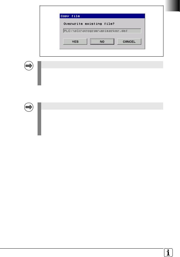
Replace the apimarker.def file:
During the update of the NC software, a new version of the apimarker.def file was automatically copied to the PLC partition of the control. Proceed as follows:
Switch to the Organization mode of operation.
Enter the code number 95148 to call the Machine Parameter mode of operation.
Press the END soft key and switch the soft-key row.
Press the PGMMGT  soft key to open the file manager.
Switch to the PLC:\proto\plc directory.
Copy the apimarker.def file to the program directory of your PLC program. Overwrite the existing apimarker.def file:
18 |
HEIDENHAIN Technical Manual MANUALplus 620 |
Note
Please also copy the apimarker.def file to your PC as well, and add it to the PLCdesignNT project. Otherwise, during the next transfer of PLC project files to the control, the file might be overwritten by the old version.
Note
After an update, please modify the previous file oem_turning.mcg as described below, and add it to the PLCdesignNT project. Otherwise, during the next transfer of PLC project files to the control, the file oem_turning.mcg might be overwritten by the old version, which leads to an error.
Modify the max. number of spindles in the file oem.mcg or oem_turning.mcg:
To modify the max. number of spindles in the PLC file oem.mcg or oem_turning.mcg, proceed as follows:
...
DEFINE SPINDLE_COUNT |
= 6 |
; (old: =4) |
...
November 2010 |
1.2 NC Software 548 328-02 |
19 |

Note
After an update, please modify the previous file plc.cfg as described below, and add it to the PLCdesignNT project. Otherwise, during the next transfer of PLC project files to the control, the file plc.cfg might be overwritten by the old version, which leads to an error (Fatal Error Syntax).
Modify the plc.cfg file:
The current plc.cfg file is located in the control in the directory PLC:\config\lathe\manplus\plc.cfg. You can use TNCremoNT to copy the file from the control to the PLC project, or you can use PLCdesignNT to modify the previous file in the PLC project.
Make the following changes to the plc.cfg file:
CfgPlcOverrideDev ( |
|
key:="PotentiometerF", |
|
source:=OVR1, |
|
mop:="MB", |
; This line must be added. |
mode:=LINEAR, |
|
values:=[] |
|
) |
|
CfgPlcOverrideDev ( |
|
key:="PotentiometerS", |
|
source:=OVR2, |
|
mop:="MB", |
; This line must be added. |
mode:=LINEAR, |
|
values:=[] |
|
) |
|
CfgPlcStrobes ( |
|
... |
|
sStrobe:=[ |
; Add an opening bracket |
"S1" |
|
], |
; Add a closing bracket |
... |
|
) |
|
20 |
HEIDENHAIN Technical Manual MANUALplus 620 |
CfgPlcOverrideS (
key:="S1", |
|
minimal:=0.5, |
|
maximal:=1.5, |
|
source:= [ |
; Add an opening bracket |
"PotentiometerS" |
|
] |
; Add a closing bracket |
)
CfgPlcOverrideS (
key:="S2", |
|
minimal:=1, |
|
maximal:=1, |
|
source:= [ |
; Add an opening bracket |
"PotentiometerS" |
|
] |
; Add a closing bracket |
)
CfgPlcOverrideF (
key:="CH_NC1", |
|
minimal:=0, |
|
maximal:=1.5, |
|
source:= [ |
; Add an opening bracket |
"PotentiometerF" |
|
] |
; Add a closing bracket |
) |
|
CfgPlcMop ( |
; Add this and all the following data |
key:="MB", |
|
type:=MB, |
|
primary:=FALSE,
omg:=0,
spindle:=0
)
CfgPlcMop ( key:="HR", type:=HR, primary:=FALSE, omg:=0, spindle:=0
)
November 2010 |
1.2 NC Software 548 328-02 |
21 |

Note
Please observe the following note if you
are using the HEIDENHAIN PLC Basic Program!
It is essential that you check and modify the PLC program:
The behavior of the symbolic API marker NN_ChnProgCancel (NC program cancelation) has been changed: NN_ChnProgCancel will now be set every time the NC program is canceled. For a normal end of program,
NN_ChnProgEnd will be set. The NN_ChnProgCancel marker remains set during the complete Cancel cycle and beyond the program end until the next NC program is started.
When a program is canceled, the NN_ChnProgEnd marker will not be set. The end of program run, including the execution of a Cancel cycle, has been reached when NN_ChnControlInOperation is reset. NN_ChnProgCancel and NN_ChnProgEnd will be reset when NN_ChnControlInOperation is set again.
If both NN_ChnProgCancel and NN_ChnControlInOperation are set, this indicates that the Cancel cycle is being executed.
Module 9429 or 9320 can be used to inquire the reason for the program cancelation.
Please check the following lines in the PLC basic program and modify them if required:
German: Biblioth.src
;External/Internal STOP
L |
ApiChn.NN_ChnProgCancel |
AN |
ML_Internal_STOP |
=MG_Impuls_Internal_STOP
L ApiChn.NN_ChnProgCancel
=ML_Internal_STOP
English: Library.src
;External/Internal STOP
L |
ApiChn.NN_ChnProgCancel |
AN |
ML_Internal_STOP |
=MG_pulse_internal_stop
L ApiChn.NN_ChnProgCancel
=ML_Internal_STOP
22 |
HEIDENHAIN Technical Manual MANUALplus 620 |

1.2.2 Description of the new functions |
|
||
New software |
You can enable the following new software options by entering a code |
||
options |
number. HEIDENHAIN can give you the code number after having been |
||
|
informed of the SIK number: |
|
|
|
|
|
|
|
Option |
Description |
ID |
|
#10 |
Tools and technology |
632 228-01 |
|
|
Tool database expanded to 999 entries |
|
|
|
Technology database expanded to 62 workpiece- |
|
|
|
material/tool-material combinations |
|
|
|
Support of multipoint tools |
|
|
|
Tool life monitoring with exchange tools |
|
|
|
|
|
|
#17 |
Tool measurement |
632 230-01 |
|
|
Determining tool-setting dimensions with a touch |
|
|
|
probe |
|
|
|
Determining tool-setting dimensions with an |
|
|
|
optical gauge |
|
|
|
|
|
|
#41 |
Additional Language |
|
|
|
Enabling of additional conversational languages. The |
|
|
|
languages listed below can be ordered. Please |
|
|
|
contact HEIDENHAIN if you require additional |
|
|
|
conversational languages. |
|
|
|
|
|
|
|
Slovenian |
530 184-01 |
|
|
|
|
|
|
Slovak |
530 184-02 |
|
|
|
|
|
|
Latvian |
530 184-03 |
|
|
|
|
|
|
Norwegian |
530 184-04 |
|
|
|
|
|
|
Korean |
530 184-06 |
|
|
|
|
|
|
Estonian |
530 184-07 |
|
|
|
|
|
|
Turkish |
530 184-08 |
|
|
|
|
|
|
Romanian |
530 184-09 |
|
|
|
|
|
|
Lithuanian |
530 184-10 |
|
|
|
|
|
#42 |
DXF import |
632 231-01 |
|
|
Loading of DXF contours |
|
|
|
|
|
|
#70 |
Y-axis machining |
661 881-01 |
|
|
Y-axis machining |
|
|
|
|
|
|
#94 |
W-axis machining |
679 676-01 |
|
|
W-axis support |
|
|
|
|
|
November 2010 |
1.2 NC Software 548 328-02 |
23 |

Overview of the |
A summary of the improvements in NC software 548 328-02 is given below. |
|
improvements |
For more detailed information, please refer to the Technical Manual sections |
|
|
indicated in the brief descriptions given below. |
|
Machine |
New: Search for the iTNC MP number in the configuration editor |
|
Configuration |
|
For numerous machine parameters, the compatible iTNC MP number is |
|
|
stored in the help text in the configuration editor. Up to now, it has not been |
|
|
possible to search the configuration for these numbers. The search function |
|
|
of the configuration editor now enables you to search for the iTNC MP |
|
|
number (selection: MP number). See "Finding / Replacing" on page 257. |
|
New: Separate parameter numbers for OEM parameters |
|
|
|
In order for the OEM to group the parameters in the configuration editor |
|
|
according to his own needs, or to make them easier to find, there is now a |
|
|
separate number range for the OEM. Numbers 900000 to 999999 are |
|
|
reserved for the OEM. For those parameters for which an OEM number is |
|
|
defined, this number is shown instead of the HEIDENHAIN number. The |
|
|
numbers are to be defined in the |
|
|
%OEM%\config\layout\PlcUniqueNumbers.xml file. If the file is missing or |
|
|
empty, no OEM numbers will be displayed. For more information, please |
|
|
refer to “User Parameters" on page 277. |
|
Expanded: OEM motor table (only digital control) |
|
|
|
Until now, if the OEM-specific motor table (path: |
|
|
PLC:\table\motor_oem.mot) was missing, a warning was issued and the |
|
|
user had to create the table himself. Now no warning will be issued. The |
|
|
control itself creates a new blank table as soon as the MP_motName |
|
|
(401301) parameter is edited. If the OEM motor table exists but columns are |
|
|
missing, then the columns that exist in the SYS motor table will be |
|
|
transferred to the OEM motor table during copying. The control indicates |
|
|
which columns were not copied. |
|
Expanded: Saving update rules |
|
|
|
If the user tries to exit the configuration editor without saving the changes |
|
|
made by the update rules, a dialog window appears prompting the user to |
|
|
save the data. The configuration editor cannot be exited until the data are |
|
|
saved, see “Update rules" on page 265. |
|
|
|
|
|
Note |
|
|
|
|
|
The first restart of the control after the update cannot be continued without |
|
|
saving the configuration changes made by the update rules. |
|
|
|
24 |
HEIDENHAIN Technical Manual MANUALplus 620 |

Machine |
|
|
|
parameters |
Expanded/changed machine parameters: |
||
|
|||
new/expanded/ |
|
|
|
changed |
|
|
|
|
|
|
|
MP number |
Config object |
Parameter |
Description of change |
100201 |
CfgMachineSimul |
MP_simMode |
When the new value Delivery is |
|
|
|
set, during startup of the control all |
|
|
|
axes are set to the test mode, and a |
|
|
|
switch-on of the axes is prevented. |
|
|
|
The user should then be able to |
|
|
|
start the control, even with an |
|
|
|
incomplete or faulty axis |
|
|
|
configuration in order to put the |
|
|
|
axes into operation. After the |
|
|
|
configuration of all axes has been |
|
|
|
completed, the control can be |
|
|
|
switched to full operation |
|
|
|
(FullOperation). |
|
|
|
If Delivery, CcAndExt or CcOnly is |
|
|
|
set, the control now no longer |
|
|
|
outputs any analog nominal values. |
|
|
|
|
102902 |
CfgFileType |
MP_standardEditor |
"TEXT-EDITOR" can now be selected |
|
|
|
in order to assign the ASCII editor of |
|
|
|
the control to a file type. |
|
|
|
|
103502 |
CfgPlcTimer |
MP_value |
The input range of the parameter was |
|
|
|
expanded from 1 000 to 1 000 000 |
|
|
|
seconds (corresponds to approx. 11.5 |
|
|
|
days). |
|
|
|
|
104300 |
CfgPlcOverrideDev |
– |
The reaction of the parameters under |
104400 |
CfgPlcOverrideS |
|
CfgPlcOverrideDev, CfgPlcOverrideS, |
|
|
|
CfgPlcOverrideF and |
|
|
|
CfgPlcOverrideR was changed from |
|
|
|
NOTHING to RESET. The control |
|
|
|
must now be rebooted after a |
|
|
|
parameter change. |
|
|
|
|
105201 |
CfgSystemTime |
MP_offsetToUTC |
Values with decimal places can now |
|
|
|
be entered for time differences to |
|
|
|
universal time (GMT). This is |
|
|
|
necessary for parts of Australia (+8.5 |
|
|
|
and +9.5 hours) and Kazakhstan (+3.5 |
|
|
|
hours), for example. Also, the |
|
|
|
maximum value was extended from |
|
|
|
+13 to +14 [hours]. |
|
|
|
|
400011 |
CfgAxisHardware |
MP_posEncoder |
The default value of the parameter |
|
|
Resistor |
was changed from without to |
|
|
|
120 ohm. |
|
|
|
|
November 2010 |
1.2 NC Software 548 328-02 |
25 |

New machine parameters:
MP |
Config object |
Parameter |
Description |
number |
|
|
|
102907 |
CfgFileType |
MP_protect |
Disables filtering or editing of a file |
|
|
|
type, see page 1192. |
|
|
|
|
104018 |
CfgPlcSStrobe |
MP_cuttingSpeed |
Optional parameter – If parts of the |
|
|
|
configuration indicate the symbolic |
|
|
|
name or number of a word marker to |
|
|
|
which the cutting speed is copied. |
|
|
|
|
104304 |
CfgPlcOverrideDev |
MP_mop |
In MP_mop, enter the key name of |
|
|
|
the machine operating panel on which |
|
|
|
the override source is located, see |
|
|
|
page 986. |
|
|
|
|
106501 |
CfgConfigSettings |
MP_undoListSize |
Defines the number of entries in the |
|
|
|
parameter change list, see page 257. |
|
|
|
|
106502 |
|
MP_suppressUsrMsg |
This parameter is used to suppress |
|
|
|
the warning Key is non-functional, |
|
|
|
see page 930. |
|
|
|
|
106503 |
|
MP_dispParam |
Specifies whether MP numbers or |
|
|
Numbers |
symbolic names are displayed in the |
|
|
|
parameter change list, see page 257. |
|
|
|
|
106504 |
|
MP_hideWrite |
If the parameter is set to TRUE, |
|
|
Protected |
write-protected parameters are |
|
|
|
hidden in the configuration editor, see |
|
|
|
page 264. |
|
|
|
|
116103 |
CfgPlcSymName |
MP_dbLoadDisplay |
The parameter defines the variable |
|
|
|
name for the dashboard load display, |
|
|
|
see page 1036. |
|
|
|
|
203804 |
CfgChannelProperties |
MP_kinManualMode |
Y axis as oblique axis: Activate the |
|
|
|
compensating motion in Manual |
|
|
|
mode as well, see page 1071. |
|
|
|
|
300110 |
CfgAxis |
MP_deactivatedAtStart |
Deactivate the axis or spindle during |
|
|
|
start-up, see page 448. |
|
|
|
|
300111 |
|
MP_restoreModuloCntr |
Save modulo counter of the axis in |
|
|
|
SRAM, see page 403. |
|
|
|
|
300205 |
CfgAxisPropKin |
MP_parAxComp |
Define the compensation for parallel |
|
|
|
minor axes, see page 1079. |
|
|
|
|
401509 |
CfgSpindle |
MP_changeTurnDir |
Rotational direction reversal with M3 |
|
|
|
and M4, see page 435. |
|
|
|
|
601801 |
CfgGlobalProperties |
MP_lifeTime |
Activate tool life monitoring for tool |
|
|
|
service age or workpiece quantity, |
|
|
|
see page 1038. |
|
|
|
|
601806 |
CfgGlobalProperties |
MP_doProgAfterTCall |
Run subprogram after the tool |
|
|
|
change, see page 1072. |
|
|
|
|
26 |
HEIDENHAIN Technical Manual MANUALplus 620 |

MP |
Config object |
Parameter |
Description |
number |
|
|
|
604601 |
CfgToolMeasuring |
MP_measuringType |
Type of tool measurement, see page |
|
|
|
1018. |
|
|
|
|
604602 |
|
MP_feed |
Tool measurement: Measuring feed |
|
|
|
rate, see page 1018. |
|
|
|
|
604603 |
|
MP_distance |
Tool measurement: Measuring range, |
|
|
|
see page 1018. |
|
|
|
|
604701 |
CfgProbePosition |
MP_positionProbePos |
Tool measurement: Position of the |
|
|
|
touch probe in positive axis direction, |
|
|
|
see page 1019. |
|
|
|
|
604702 |
|
MP_positionProbeNeg |
Tool measurement: Position of the |
|
|
|
touch probe in negative axis direction, |
|
|
|
see page 1019. |
|
|
|
|
604703 |
|
MP_maxMeasuringFeed |
Tool measurement: Maximum |
|
|
|
permissible measuring feed rate, see |
|
|
|
page 1019. |
|
|
|
|
604801 |
CfgGlbDispSettings |
MP_plcSpindleSelect |
Selection of spindle number by PLC, |
|
|
|
see page 1039. |
|
|
|
|
November 2010 |
1.2 NC Software 548 328-02 |
27 |

Operation and technology
Machine interfacing
Enhanced: Dashboard display of PLC signals
The attribute evaluation of the dashboard element "LoadDisplay" was enhanced so that PLC data can now optionally also be transferred to this element. Therefore, it is now also possible for analog control to realize a load display for axis and spindle drives directly in the dashboard, see “Load display for analog drives" on page 1036.
Enhanced: Update of NC software
The NC software can now also be updated while it is running. The new code number 231019 was therefore introduced, see “Start update while software is running on the control" on page 98.
Enhanced: Log
The display of the control's log was improved. The accumulated keystrokes are now stored simultaneously with the control events in the log and are displayed in table view.
In order to be able to track machine operation or machine conditions systematically, detailed additional information is entered and stored simultaneously with all important log entries, such as keystrokes, errors, system errors or warnings, see “Error messages and log files" on page 907.
Enhanced: Display of configuration errors during start-up
If configuration errors occur during control start-up, the Error during start-up message appears instead of Power interrupted. Also, the error messages for the incorrect configuration data, which are triggered by the applications, are displayed individually.
New: Additional data types for table columns
The control supports additional data types for columns in NC tables. The FEED_CUT column data type applies to the cutting speed in units of m/min or feet/min. The FEED_ROT column data type applies to the feed rate per revolution in units of mm/rev or inch/rev. As usual, the new column data types are listed as enumeration values of parameter MP_unit (105602) of the configuration object CfgColumnDescription.
Enhanced: Integrated oscilloscope – Selection of symbolic operands
In the MIOTC dialog (dialog box for selecting markers, inputs, outputs, timers and counters) in the integrated oscilloscope, symbolic API operands can now also be selected and displayed conveniently in a list. See "Setup for digital signals" on page 806.
New: Integrated oscilloscope – Circular interpolation test
A circular interpolation test can now be performed with the integrated oscilloscope. See "Circular interpolation test with the integrated oscilloscope" on page 814.
New: Test of internal EMERGENCY STOP by code number
For test purposes, the behavior during an internal EMERGENCY STOP can now be simulated in order to inspect the correct wiring of the machine. The control-is-ready output is reset, and the NC and PLC are no longer operable. It is essential that you support hanging axes before the test in order to prevent damage to the machine in case of error. To start the test, press the CODE NUMBER soft key and enter the code number 6871232. Enter the code number again to reset the control status to "ready for operation."
28 |
HEIDENHAIN Technical Manual MANUALplus 620 |

Configuring the
Axes and Spindle
PLC programming
New: Software option #70 – Y-axis machining
With a Y axis you can drill and mill a workpiece on its front, back and lateral surfaces.
During use of the Y-axis, two axes interpolate linearly or circularly in the given working plane, while the third axis interpolates linearly. This enables you to machine slots or pockets, for example, with plane floors and perpendicular edges. By defining the spindle angle, you can determine the position of the milling contour on the workpiece.
If the Y axis is to be positioned at an angle not equal to 90° to the X or Z axis, the Y axis can also be configured as an oblique axis.
For configuring the Y axis, please refer to “Configuring the Y axis" on page 1066. For information on programming the Y axis, please refer to the User’s Manual for the control.
New: Software option #94 – W-axis support
The control can now offset the display of movements in the Z axis with those of its parallel secondary axis W. The W axis is already configured in the control kinematics and can be moved via the PLC.
For more information on the configuration of the W axis, please refer to “Configuring the W axis" on page 1073.
New: Spindle change key
Starting immediately, a spindle change key can be supported by the PLC. It assigns the input (TSF dialog) to the selected spindle. The selected spindle is identified in the corresponding display element of the dashboard. See “Selection of spindle and channel by PLC" on page 1039.
Enhanced: Backlash compensation
If nonlinear axis-error compensation is active, MP_backLash can now be used to activate backlash compensation in addition to the compensation-value tables, see “Axis Error Compensation" on page 467.
Enhanced: Symbolic memory interface (API 3.0) – New operands introduced:
PLC operand / Description |
Model |
|
|
NP_ChnProgSelected |
M |
NC program selected |
|
This marker can be used to interrogate whether an |
|
NC program is selected in the Program Run modes of |
|
operation. The marker is not set if an NC program is |
|
selected from a pallet table. |
|
|
|
NN_ChnFeedRapidTraverseActive |
M |
0:Rapid traverse is active (FMAX)
1:Rapid traverse is not active
Changed: Behavior of NN_ChnToolLifeExpired (tool life 1 expired)
The status of NN_ChnToolLifeExpired is now reset by the PLC runtime system after the end of an NC program.
New: PLC process monitor
In the PLC programming mode you can use the MONITOR and PROCESS MONITOR soft keys to open a status screen in which the control displays all parallel processes, as well as the process for the submit queue. See "Control of events" on page 1328.
November 2010 |
1.2 NC Software 548 328-02 |
29 |

Enhanced: Compilation of PLC program
•If the PLC program has already been compiled in the PLC Programming mode of operation before the Power interrupted message has been acknowledged, the PLC program will not be compiled again when the message is acknowledged. This change makes it possible to observe the PLC operands with the integrated oscilloscope during start-up of the PLC program:
-Start the control, do not acknowledge the Power interrupted message.
-Compile the PLC program in the PLC Programming mode of operation.
-Activate the integrated oscilloscope in order to observe the desired PLC operands and start the measurement.
-Acknowledge the Power interrupted message now for the control to start the PLC program.
•Now a PLC program is compiled even if the machine parameters refer to symbolic names of PLC operands that are not defined in the PLC program. The control issues an error message for every undefined symbolic name and then compiles the PLC program.
Attention
A PLC program with undefined symbolic PLC operands can lead to hazardous behavior of the machine! It is essential that you check whether the parameters for configuring the M functions (CfgPlcMStrobe) contain meaningful strobe definitions. The data of strobe definitions must be mapped onto defined PLC operands.
Enhanced: Commands for string processing
Symbolic operands (B/W/D operands) can now be used for indexed access to the string operands "S" or the PLC error and dialog files, see “Commands for String Processing" on page 1313.
Enhanced: WATCH LIST and TRACE function
New TYPE column: Type (M for marker, B for byte, W for word, etc.) of the PLC operand, see “The WATCH LIST function" on page 1100.
The ADD TO WATCH LIST soft key can be used to transfer the PLC operands of the currently highlighted line to the WATCH LIST, see “The TRACE function" on page 1104.
Enhanced: EDIT function
The features and the operation of the editor were changed. The editor is now a full-fledged ASCII editor. The cursor can be positioned in all directions and line breaks can be inserted, see “The EDIT function" on page 1107.
New: Moving PLC axes with the handwheel
It is now possible to assign a PLC axis to a handwheel via Module 9036. In the El. Handwheel mode of operation, the machine operator can use the axis keys to select a PLC axis and move it with the handwheel.
30 |
HEIDENHAIN Technical Manual MANUALplus 620 |
Loading...