


Pilot
iTNC 530
NC-Software 340 420-xx
English (en) 7/2002
The Pilot
... is your concise programming guide for the HEIDENHAIN iTNC 530 contouring control. For more comprehensive information on programming and operating, refer to the TNC User's Manual. There you will find complete information on:
•Q-parameter programming
•The central tool file
•3-D tool compensation
•Tool measurement
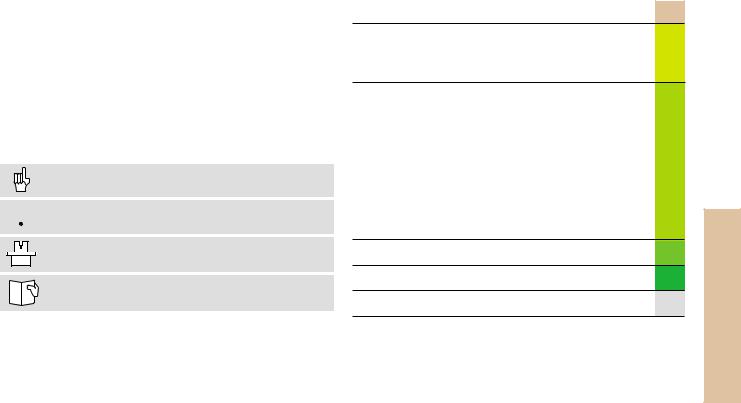
Certain symbols are used in the Pilot to denote specific types of information:
Important note
 WARNING: danger for the user or the machine!
The TNC and the machine tool must be prepared by the machine tool builder to perform these functions!
Chapter in User's Manual where you will find more detailed information on the current topic.
The information in this Pilot applies to TNCs with the following software numbers:
Control |
NC Software Number |
iTNC 530 |
340 420-xx |
|
|
Contents |
|
Fundamentals ................................................................... |
4 |
Contour Approach and Departure .................................... |
13 |
Path Functions .................................................................. |
18 |
FK Free Contour Programming ........................................ |
25 |
Subprograms and Program Section Repeats ................... |
33 |
Working with Cycles ........................................................ |
36 |
Cycles for Machining Holes and Threads ........................ |
39 |
Pockets, Studs, and Slots ................................................. |
56 |
Point Patterns ................................................................... |
65 |
SL Cycles .......................................................................... |
67 |
Cycles for Multipass Milling ............................................. |
75 |
Coordinate Transformation Cycles ................................... |
78 |
Special Cycles ................................................................... |
85 |
Graphics and Status Displays ........................................... |
88 |
ISO Programming .............................................................. |
91 |
Miscellaneous Functions M ............................................... |
97 |
Contents
3
*) Export version
Fundamentals
Fundamentals
Programs/Files

 See “Programming, File Management”
The TNC keeps its programs, tables and texts in files. A file designation consists of two components:
THREAD2.H
File name |
File type |
Maximum length: |
See table at right |
16 characters |
|
|
|
Creating a New Part Program
 Select the directory in which the program is stored
 Enter a new file name with file type
 Select unit of measure for dimensions (mm or inches)
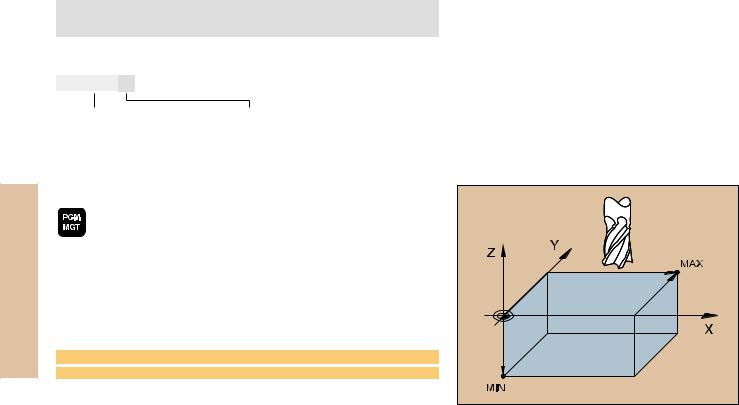
 Define the blank form (BLK) for graphics:
 Enter the spindle axis
 Enter coordinates of the MIN point: the smallest X, Y and Z coordinates
 Enter coordinates of the MAX point: the greatest X, Y and Z coordinates
1 BLK FORM 0.1 Z X+0 Y+0 Z-50
2 BLK FORM 0.2 X+100 Y+100 Z+0
Files in the TNC |
File type |
|
Programs |
|
|
• in HEIDENHAIN format |
.H |
|
• in ISO format |
.I |
|
|
|
|
Tables for |
|
|
• Tools |
.T |
|
• Datums |
.D |
|
• Pallets |
.P |
|
• Cutting data |
.CDT |
|
• Positions |
.PNT |
|
|
|
|
Texts as |
.A |
|
• ASCII files |
|
|
|
|
|
4
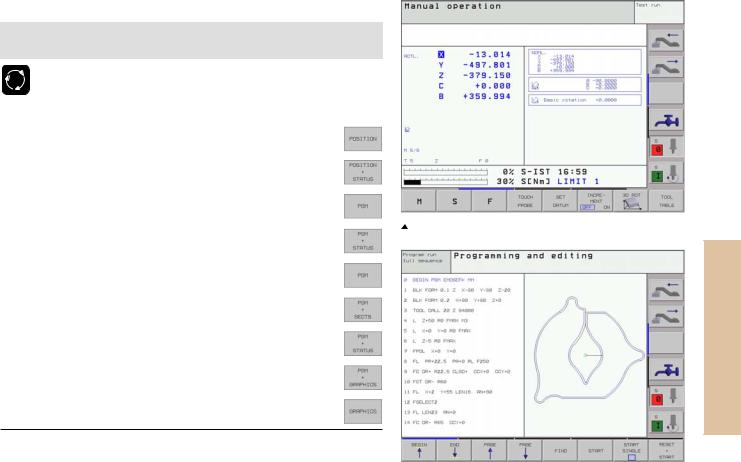
Choosing the Screen Layout

 See “Introduction, the iTNC 530”
 Show soft keys for setting the screen layout
Mode of operation |
Screen contents |
Manual operation |
Positions |
Electronic handwheel |
|
|
|
|
Positions at left |
|
Status at right |
|
|
Positioning with |
Program |
manual data input |
|
|
|
|
Program at left |
|
Status at right |
|
|
Program run, |
Program |
full sequence |
|
Program run, |
|
Program at left |
|
single block test run |
Program structure at right |
|
|
|
Program at left |
|
Status at right |
|
|
|
Program at left |
|
Graphics at right |
|
|
|
Graphics |
Continued
Positions at left, status at right  Program at left, graphics at right
Fundamentals
5
Fundamentals
Mode of operation |
Screen contents |
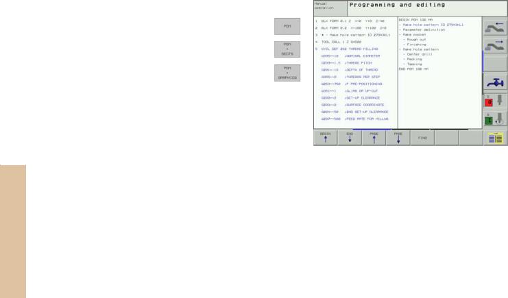
Programming and editing |
Program |
|
|
|
Program at left |
|
Program structure at right |
|
|
|
Program at left |
|
Programming graphics at right |
|
|
 Program at left, program structure at right
6

Absolute Cartesian Coordinates
The dimensions are measured from the current datum. The tool moves to the absolute coordinates.
Programmable axes in an NC block
Linear motion: |
5 axes |
|
Circular motion: |
2 |
linear axes in a plane or |
|
3 |
linear axes with cycle 19 WORKING PLANE |
Incremental Cartesian Coordinates
The dimensions are measured from the last programmed position of the tool.
The tool moves by the incremental coordinates.
Fundamentals |
7

Fundamentals
Circle Center and Pole: CC
The circle center (CC) must be entered to program circular tool movements with the path function C (see page 21). CC is also needed to define the pole for polar coordinates.
CC is entered in Cartesian coordinates*.
An absolutely defined circle center or pole is always measured from the workpiece datum.
An incrementally defined circle center or pole is always measured from the last programmed position of the workpiece.
Angle Reference Axis
Angles—such as a polar coordinate angle PA or an angle of rotation
ROT—are measured from the angle reference axis.
Working plane |
Ref. axis and 0° direction |
|
|
X/Y |
X |
|
|
Y/Z |
Y |
|
|
Z/X |
Z |
|
|
|
|
|
|
|
|
|
|
|
|
|
|
8*Circle center in polar coordinates: See FK programming
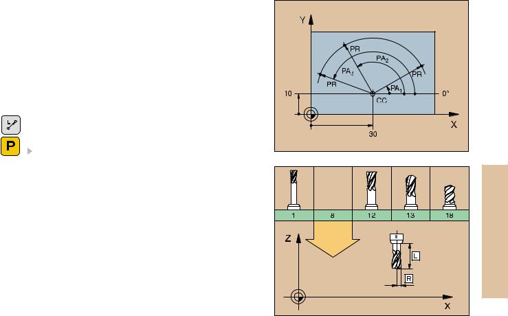
Polar Coordinates
Dimensions in polar coordinates are referenced to the pole (CC). A position in the working plane is defined by
•Polar coordinate radius PR = Distance of the position from the pole
•Polar coordinate angle PA = Angle from the angle reference axis to the straight line CC – PR
Incremental dimensions
Incremental dimensions in polar coordinates are measured from the last programmed position.
Programming polar coordinates
 Select the path function
 Press the P key
Answer the dialog prompts
Defining Tools
Tool data
Every tool is designated by a tool number between 1 and 254 or, if you are using tool tables, by a tool name.
Entering tool data
You can enter the tool data (length L and radius R)
•in a tool table (centrally, Program TOOL.T) or
•within the part program in TOOL DEF blocks (locally)
Fundamentals |
9
Fundamentals
10
 Tool number
Tool length L
 Tool radius R
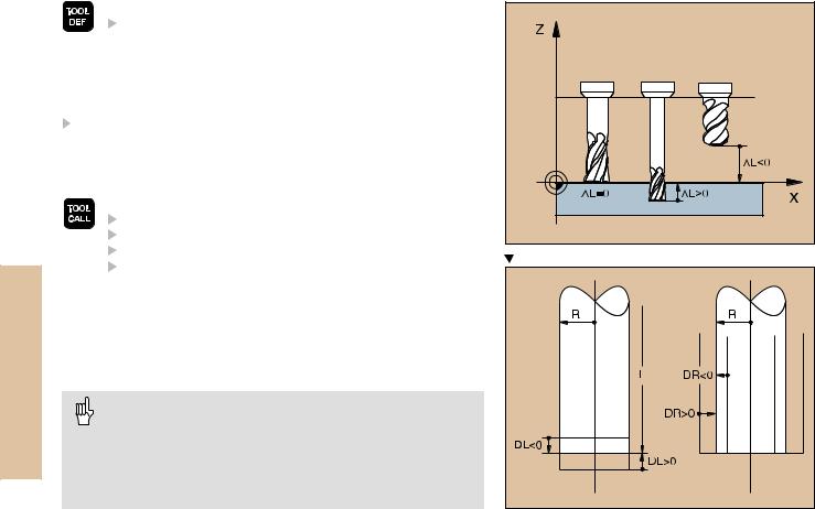
 Program the tool length as its difference DL to the zero tool:
DL>0: The tool is longer than the zero tool
DL<0: The tool is shorter than the zero tool
With a tool presetter you can measure the actual tool length, then program that length.
Calling the tool data
 Tool number or name
Working spindle axis: tool axis
Spindle speed S
Feed rate Oversizes on an end mill
Tool length oversize DL (e.g. to compensate wear)
 Tool radius oversize DR (e.g. to compensate wear)
3 |
TOOL DEF 6 |
L+7.5 R+3 |
|
4 |
TOOL CALL 6 |
Z S2000 F650 DL+1 DR+0.5 |
|
5 |
L |
Z+100 R0 |
FMAX |
6 |
L |
X-10 Y-10 |
R0 FMAX M6 |
Tool change
• Beware of tool collision when moving to the tool change position!
• The direction of spindle rotation is defined by M function: M3: Clockwise
M4: Counterclockwise
•The maximum permissible oversize for tool radius or length is ± 99.999 mm!
Tool Compensation
The TNC compensates the length L and radius R of the tool during machining.
Length compensation
Beginning of effect:
 Tool movement in the spindle axis
End of effect:
 Tool exchange or tool with the length L=0
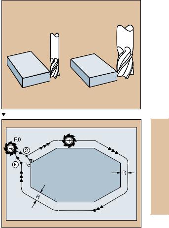
Radius compensation Beginning of effect:
 Tool movement in the working plane with RR or RL
End of effect:
 Execution of a positioning block with R0
Working without radius compensation (e.g. drilling):  Tool movement with R0
Fundamentals |
S = Start; E = End |
11
Fundamentals
Datum Setting without a 3-D Touch Probe
During datum setting you set the TNC display to the coordinates of a known position on the workpiece:
 Insert a zero tool with known radius
Select the manual operation or electronic handwheel mode
Touch the reference surface in the tool axis with the tool and enter its length
Touch the reference surface in the working plane with the tool and enter the position of the tool center
Setup and Measurement with 3-D Touch Probes
A HEIDENHAIN 3-D touch probe enables you to setup the machine very quickly, simply and precisely.
Besides the probing functions for workpiece setup on the Manual and Electronic Handwheel modes, the Program Run modes provide a series of measuring cycles (see also the User's Manual for Touch Probe Cycles):
•Measuring cycles for measuring and compensating workpiece misalignment
•Measuring cycles for automatic datum setting
•Measuring cycles for automatic workpiece measurement with tolerance checking and automatic tool compensation
12
Contour Approach and Departure
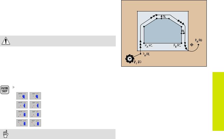
Starting point PS
PS lies outside of the contour and must be approached without radius compensation.
Auxiliary point PH
PH lies outside of the contour and is calculated by the TNC.
The tool moves from the starting point PS to the auxiliary point PH at the feed rate last programmed feed rate!
First contour point PA and last contour point PE
The first contour point PA is programmed in the APPR (approach) block. The last contour point is programmed as usual.
End point PN
PN lies outside of the contour and results from the DEP (departure) block. PN is automatically approached with R0.
Path Functions for Approach and Departure
Contour Approach and Departure |
Press the soft key with the desired path function: |
|
Straight line with tangential connection |
|
Straight line perpendicular to the |
|
contour point |
|
Circular arc with tangential connection |
|
Straight line segment tangentially con- |
|
nected to the contour through an arc |
|
• Program a radius compensation in the APPR block! |
|
• DEP blocks set the radius compensation to 0! |
13 |
Contour Approach and Departure
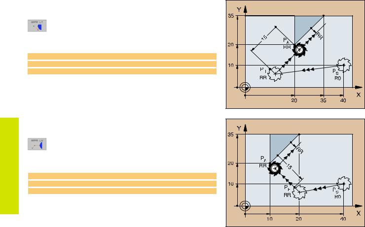
Approaching on a Straight Line with Tangential Connection
 Coordinates for the first contour point PA
 Distance Len (length) from PH to PA Enter a length Len > 0
 Tool radius compensation RR/RL
7 L X+40 Y+10 R0 FMAX M3
8 APPR LT X+20 Y+20 LEN 15 RR F100
9 L X+35 Y+35
Approaching on a Straight Line Perpendicular to the First Contour Element
 Coordinates for the first contour point PA
 Distance Len (length) from PH to PA Enter a length Len > 0
 Tool radius compensation RR/RL
7 L X+40 Y+10 R0 FMAX M3
8 APPR LN X+10 Y+20 LEN 15 RR F100
9 L X+20 Y+35
14

Approaching Tangentially on an Arc |
|
|
|
Coordinates for the first contour point PA |
|
|
Radius R |
|
|
Enter a radius R > 0 |
ApproachContour Departureand |
|
Circle center angle (CCA) |
|
|
|
|
|
Enter a CCA > 0 |
|
|
Tool radius compensation RR/RL |
|
7 |
L X+40 Y+10 R0 FMAX M3 |
|
8 |
APPR CT X+10 Y+20 CCA 180 R10 RR F100 |
|
9 |
L X+20 Y+35 |
|
Approaching Tangentially on an Arc and a Straight Line
 Coordinates for the first contour point PA
 Radius R
Enter a radius R > 0
 Tool radius compensation RR/RL
7 L X+40 Y+10 R0 FMAX M3
8 APPR LCT X+10 Y+20 R10 RR F100
9 L X+20 Y+35
15 |
Contour Approach and Departure
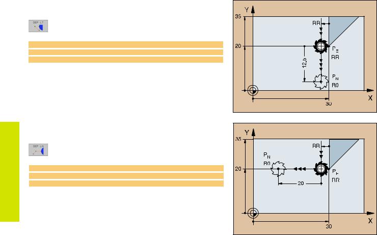
Departing Tangentially on a Straight Line
 Distance Len (length) from PE to PN
Enter a length Len > 0
23 L X+30 Y+35 RR F100
24 L Y+20 RR F100
25 DEP LT LEN 12.5 F100 M2
Departing on a Straight Line Perpendicular to the Last Contour Element
 Distance Len (length) from PE to PN Enter a length Len > 0
23 L X+30 Y+35 RR F100
24 L Y+20 RR F100
25 DEP LN LEN+20 F100 M2
16
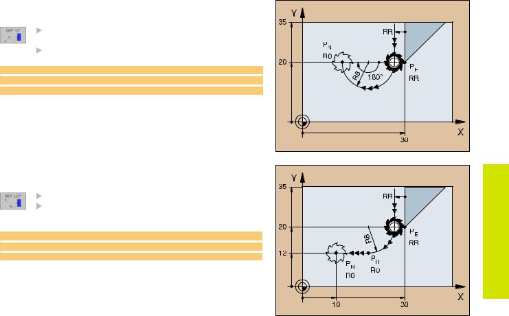
Departing Tangentially on an Arc |
|
|
Radius R |
|
Enter a radius R > 0 |
|
Circle center angle (CCA) |
23 |
ContourApproach Departureand |
L X+30 Y+35 RR F100 |
|
24 |
L Y+20 RR F10 |
25 |
DEP CT CCA 180 R+8 F100 M2 |
Departing on an Arc Tangentially Connecting |
|
the Contour and a Straight Line |
|
|
Coordinates of the end point PN |
|
Radius R |
|
Enter a radius R > 0 |
23 |
L X+30 Y+35 RR F100 |
24 |
L Y+20 RR F100 |
25 |
DEP LCT X+10 Y+12 R8 F100 M2 |
|
17 |

Path Functions
18
Path Functions for Positioning Blocks

 See „Programming: Programming contours“.
Programming the Direction of Traverse
Regardless of whether the tool or the workpiece is actually moving, you always program as if the tool is moving and the workpiece is stationary.
Entering the Target Positions
Target positions can be entered in Cartesian or polar coordinates – either as absolute or incremental values, or with both absolute and incremental values in the same block.
Entries in the Positioning Block
A complete positioning block contains the following data:
•Path function
•Coordinates of the contour element end points (target position)
•Radius compensation RR/RL/R0
•Feed rate F
•Miscellaneous function M
Before you execute a part program, always pre-position the tool to prevent the possibility of damaging the tool or workpiece!
Path functions
Straight line |
Page 19 |
|
Chamfer between two |
Page 20 |
|
straight lines |
||
|
||
Corner rounding |
Page 20 |
|
Circle center or pole for |
Page 21 |
|
polar coordinates |
||
|
||
Circular patharound the |
Page 21 |
|
circle center CC |
||
|
||
Circular path with |
Page 22 |
|
known radius |
||
|
||
Circular path with |
Page 23 |
|
tangential connection to |
||
previous contour |
|
|
FK Free Contour |
Page 25 |
|
Programming |
||
|
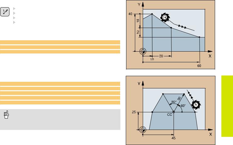
Straight Line |
|
|
Coordinates of the straight line end point |
|
Tool radius compensation RR/RL/R0 |
|
Feed rate F |
|
Miscellaneous function M |
|
FunctionsPath |
With Cartesian coordinates: |
|
7 |
L X+10 Y+40 RL F200 M3 |
8 |
L IX+20 IY-15 |
9 |
L X+60 IY-10 |
With polar coordinates:
12 CC X+45 Y+25
13 LP PR+30 PA+0 RR F300 M3
14 LP PA+60
15 LP IPA+60
16 LP PA+180
• You must first define the pole CC before you can program polar coordinates!
•Program the pole CC only in Cartesian coordinates!
•The pole CC remains effective until you define a new one!
19 |
Path Functions
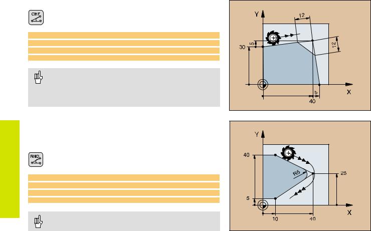
Inserting a Chamfer Between Two Straight Lines
 Chamfer side length
 Feed rate F for the chamfer
7 L X+0 Y+30 RL F300 M3
8 L X+40 IY+5
9 CHF 12 F250
10 L IX+5 Y+0
• You cannot start a contour with a CHF block!
• The radius compensation before and after the CHF block must be the same!
•An inside chamfer must be large enough to accommodate the current tool!
Corner Rounding
The beginning and end of the arc extend tangentially from the previous and subsequent contour elements.
 Radius R of the circular arc
 Feed rate F for corner rounding
5 L X+10 Y+40 RL F300 M3
6 L X+40 Y+25
7 RND R5 F100
8 L X+10 Y+5
|
An inside arc must be large enough to accommodate the |
20 |
current tool! |
|
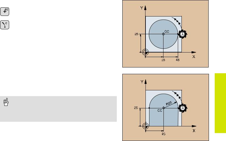
Circular Path Around the Circle Center CC
 Coordinates of the circle center CC
 Coordinates of the arc end point
 Direction of rotation DR
C and CP enable you to program a complete circle in one block.
With cartesian coordinates:
5 |
CC X+25 Y+25 |
|
|
|
|
6 |
L X+45 |
Y+25 |
RR |
F200 M3 |
|
7 |
C X+45 |
Y+25 |
DR+ |
|
|
With polar coordinates: |
|
|
|||
|
|
|
|
||
18 |
CC X+25 Y+25 |
|
|
||
19 |
LP PR+20 PA+0 |
RR F250 |
M3 |
||
20 |
CP PA+180 DR+ |
|
|
||
• Define the pole CC before programming polar coordinates!
• Program the pole CC only in Cartesian coordinates!
•The pole CC remains effective until you define a new one!
•The arc end point can be defined only with the polar coordinate angle (PA)!
Path Functions
21
Path Functions
Circular Path with Known Radius (CR)
Coordinates of the arc end point
Radius R
If the central angle ZW > 180, R is negative. If the central angle ZW < 180, R is positive.  Direction of rotation DR
10 |
L X+40 Y+40 RL F200 M3 |
Arc starting point |
||||
11 |
CR |
X+70 |
Y+40 |
R+20 |
DR- |
Arc 1 or |
11 |
CR |
X+70 |
Y+40 |
R+20 |
DR+ |
Arc 2 |
|
|
|
|
|
|
|
10 |
L X+40 Y+40 RL F200 M3 |
Arc starting point |
||||
11 |
CR |
X+70 |
Y+40 |
R-20 |
DR- |
Arc 3 or |
11 |
CR |
X+70 |
Y+40 |
R-20 |
DR+ |
Arc 4 |
Arcs 1 and 2 |
|
Arcs 3and 4 |
||||||||||||||||
|
|
|
|
|
|
|
|
|
|
|
|
|
|
|
|
|
|
|
|
|
|
|
|
|
|
|
|
|
|
|
|
|
|
|
|
|
|
|
|
|
|
|
|
|
|
|
|
|
|
|
|
|
|
|
|
|
|
|
|
|
|
|
|
|
|
|
|
|
|
|
|
|
|
|
|
|
|
|
|
|
|
|
|
|
|
|
|
|
|
|
|
|
|
|
|
|
|
|
|
|
|
|
|
|
|
|
|
|
|
|
|
|
|
|
|
|
|
|
|
|
|
|
|
|
|
|
|
|
|
|
|
|
|
|
|
|
|
|
|
|
|
|
|
|
|
|
|
|
|
|
|
|
|
|
|
|
|
|
|
|
|
|
|
|
|
|
|
|
|
|
|
|
|
|
|
|
|
|
|
|
|
|
|
|
|
|
|
|
|
|
|
|
|
|
|
|
|
|
|
|
|
|
|
|
|
|
|
|
|
|
|
|
|
|
|
|
|
|
|
|
|
|
|
|
|
|
|
|
|
|
|
|
|
|
|
|
|
|
|
|
|
|
|
|
|
|
22
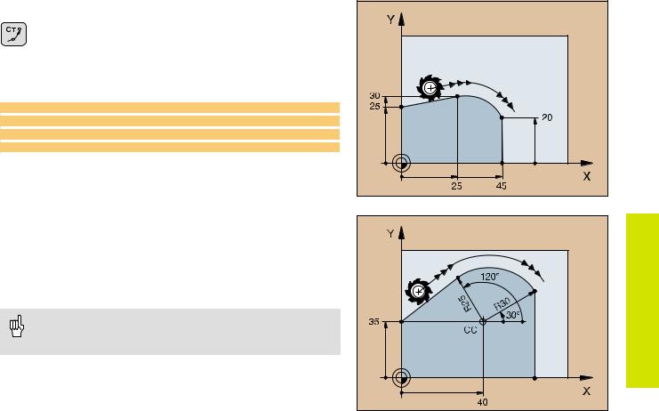
Circular Path CT with Tangential Connection
 Coordinates of the arc end point
 Radius compensation RR/RL/R0
 Feed rate F
  Miscellaneous function M
With cartesian coordinates:
5 L X+0 Y+25 RL F250 M3
6 L X+25 Y+30
7 CT X+45 Y+20
8 L Y+0
With polar coordinates:
12 |
CC X+40 Y+35 |
|
13 |
L |
X+0 Y+35 RL F250 M3 |
14 |
LP PR+25 PA+120 |
|
15 |
CTP PR+30 PA+30 |
|
16 |
L |
Y+0 |
• Define the pole CC before programming polar coordinates!
• Program the pole CC only in Cartesian coordinates!
• The pole CC remains effective until you define a new one!
Path Functions |
23 |
Path Functions
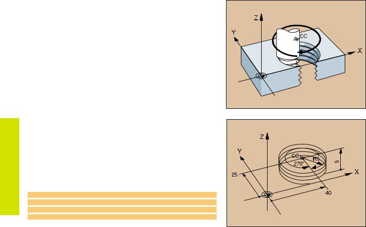
Helix (Only in Polar Coordinates)
Calculations (upward milling direction) |
|
|
|
|
|
|
|
|
||||
Path revolutions: |
n |
= |
Thread revolutions + overrun at start and |
|
|
|
|
|
|
|
||
|
|
|
end of thread |
|
|
|
|
|
|
|
|
|
Total height: |
h |
= |
Pitch P x path revolutions n |
|
|
|
|
|
|
|
||
Incr. coord. angle: |
IPA = |
Path revolutions n x 360° |
|
|
|
|
|
|
|
|||
Start angle: |
PA |
= |
Angle at start of thread + angle for |
|
|
|
|
|
|
|
||
|
|
|
overrun |
|
|
|
|
|
|
|
|
|
|
|
|
|
|
|
|
|
|
|
|
|
|
Start coordinate: |
Z |
= |
Pitch P x (thread revolutions + thread |
|
|
|
|
|
|
|
||
|
|
|
|
|
|
|
||||||
|
|
|
overrun at start of thread) |
|
|
|
|
|
|
|
||
Shape of helix |
|
|
|
|
|
|
|
|
|
|
|
|
|
|
|
|
|
|
|
|
|
|
|
|
|
|
|
|
|
|
|
|
|
|
|
|
||
Internal thread |
Work direction |
Direction |
Radius comp. |
|
|
|
|
|
|
|
||
Right-hand |
Z+ |
|
|
DR+ |
RL |
|
|
|
|
|
|
|
|
|
|
|
|
|
|
|
|
||||
Left-hand |
Z+ |
|
|
DR– |
RR |
|
|
|
|
|
|
|
|
|
|
|
|
|
|
|
|
|
|
|
|
Right-hand |
Z– |
|
|
DR– |
RR |
|
|
|
|
|
|
|
Left-hand |
Z– |
|
|
DR+ |
RL |
|
|
|
|
|
|
|
|
|
|
|
|
|
|
|
|
|
|
|
|
External thread |
|
|
|
|
|
|
|
|
|
|
|
|
Right-hand |
Z+ |
|
|
DR+ |
RR |
|
|
|
|
|
|
|
Left-hand |
Z+ |
|
|
DR– |
RL |
|
|
|
|
|
|
|
Right-hand |
Z– |
|
|
DR– |
RL |
|
|
|
|
|
|
|
Left-hand |
Z– |
|
|
DR+ |
RR |
|
|
|
|
|
|
|
|
|
|
|
|
|
|
|
|
|
|
|
|
M6 x 1 mm thread with 5 revolutions:
12 CC X+40 Y+25
13 L Z+0 F100 M3
14 LP PR+3 PA+270 RL
15 CP IPA-1800 IZ+5 DRRL F50
24
FK Free Contour Programming
See “Programming Tool Movements – FK Free Contour
Programming”
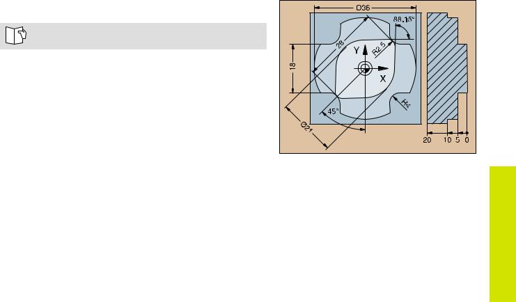
If the end point coordinates are not given in the workpiece drawing or if the drawing gives dimensions that cannot be entered with the gray path function keys, you can still program the part by using the “FK Free Contour Programming.”
Possible data on a contour element:
•Known coordinates of the end point
•Auxiliary points on the contour element
•Auxiliary points near the contour element
•A reference to another contour element
•Directional data (angle) / position data
•Data regarding the course of the contour
To use FK programming properly:
•All contour elements must lie in the working plane.
•Enter all available data on each contour element.
•If a program contains both FK and conventional blocks, the FK contour must be fully defined before you can return to conventional programming.
FK Free Contour Programming |
 These dimensions can be programmed with FK
25

Programming
FK Free Contour
Working with the Interactive Graphics
Select the PGM+GRAPHICS screen layout!
The interactive graphics show the contour as you are programming it. If the data you enter can apply to more than one solution, the following soft keys will appear:
To show the possible solutions
To enter the displayed solution in the part program
To enter data for subsequent contour elements
To graphically display the next programmed block
Standard colors of the interactive graphics
Fully defined contour element
The displayed element is one of a limited number of possible solutions
The element is one of an infinite number of solutions
Contour element from a subprogram
26
Initiating the FK Dialog
Initiate the FK dialog
Straight Circular
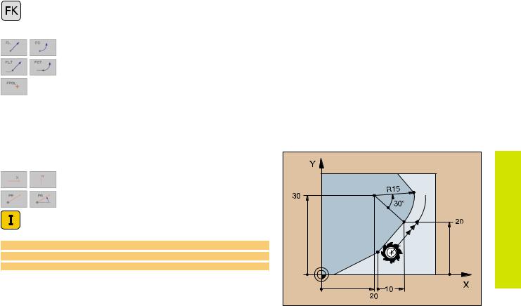
Contour element without tangential connection
Contour element with tangential connection
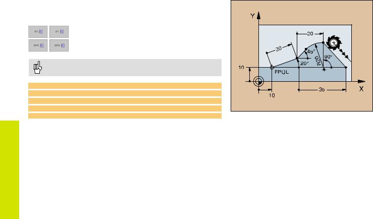
Pole for FK programming
End Point Coordinates X, Y or PA, PR
Cartesian coordinates X and Y
Polar coordinates referenced to FPOL
Incremental input
7 FPOL X+20 Y+30
8 FL IX+10 Y+20 RR F100
9 FCT PR+15 IPA+30 DR+ R15
Programming
FK Free Contour
27 |
Programming
FK Free Contour
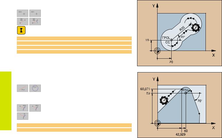
Circle Center (CC) in an FC/FCT block
Cartesian coordinates of the circle center
Polar coordinates of the circle center referenced to FPOL
Incremental input
10 FC CCX+20 CCY+15 DR+ R15
11 FPOL X+20 Y+15
...
13 FC DR+ R15 CCPR+35 CCPA+40
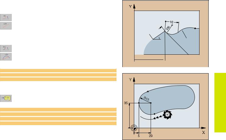
Auxiliary Points
... P1, P2, P3 on a contour
For straight lines: up to 2 auxiliary points For circles: up to 3 auxiliary points
... next to a contour
Coordinates of the auxiliary points
Perpendicular distance
13 FC DRR10 P1X+42.929 P1Y+60.071
14 FLT AN-70 PDX+50 PDY+53 D10
28
Direction and Length of the Contour Element
Data on a straight line
Gradient angle of a straight line
Length of a straight line
Data on a circular path 


 ContourProgramming
Gradient angle of the entry tangent
Length of an arc chord  Free
Free  FK
FK
27 FLT X+25 LEN 12.5 AN+35 RL F200
28 FC DR+ R6 LEN 10 AN-45
29 FCT DRR15 LEN 15
Identifying a closed contour
Beginning: CLSD+
End: CLSD–
12 L X+5 Y+35 RL F500 M3
13 FC DRR15 CLSD+ CCX+20 CCY+35
...
17 FCT DR- R+15 CLSD-
29 |
Programming
FK Free Contour
Values Relative to Block N:
Entering Coordinates
Cartesian coordinates relative to block N
Polar coordinates relative to block N
• Relative data must be entered incrementally!
• CC can also be programmed in relative values!
12 FPOL X+10 Y+10
13 FL PR+20 PA+20
14 FL AN+45
15 FCT IX+20 DRR20 CCA+90 RX 13
16 FL IPR+35 PA+0 RPR 13
30
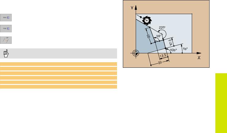
Values Relative to Block N: |
|
||
Direction and Distance of the Contour Element |
|
||
|
Gradient angle |
|
|
|
Parallel to a straight contour element |
ContourFreeFK Programming |
|
|
Parallel to the entry tangent of an arc |
||
|
Distance from a parallel element |
||
|
|
||
|
Always enter relative values incrementally! |
|
|
17 |
FL LEN 20 |
AN+15 |
|
18 |
FL AN+105 |
|
|
19 |
FL LEN 12.5 PAR 17 DP 12.5 |
|
|
20 |
FSELECT 2 |
|
|
21 |
FL LEN 20 |
IAN+95 |
|
22 |
FL IAN+220 RAN 18 |
|
|
31
 Loading...