


User's Manual
July 2004
TNC Guideline:
From workpiece drawing to program-controlled machining
Step |
Task |
TNC operating |
Starting |
|
|
|
mode |
on page |
|
|
Preparation |
|
|
|
|
|
|
|
|
1 |
Select tools |
—— |
—— |
|
|
|
|
|
|
2 |
Set workpiece datum for |
|
|
|
|
coordinate system |
—— |
—— |
|
|
|
|
|
|
3 |
Determine spindle speeds |
|
|
|
|
and feed rates |
as desired |
107, 116 |
|
|
|
|
|
|
4 |
Switch on TNC and machine |
—— |
17 |
|
|
|
|
|
|
5 |
Cross over reference marks |
|
|
17 |
|
|
|
|
|
6 |
Clamp workpiece |
—— |
—— |
|
7Set datum /
Reset position display ...
7a |
... with the probing functions |
33 |
|
|
|
|
|
|
|||||||||||||||||||||||||||||||||||
|
|
|
|
|
|
|
|
|
|
|
|
|
|
|
|
|
|
|
|
|
|
|
|
|
|
|
|
|
|
|
|
|
|
|
|
|
|
|
|
|
|
|
|
7b |
... without the probing functions |
31 |
|
|
|
|
|
|
|||||||||||||||||||||||||||||||||||
|
|
|
|
|
|
|
|
|
|
|
|
|
|
|
|
|
|
|
|
|
|
|
|
|
|
|
|
|
|
|
|
|
|
|
|
|
|
|
|
|
|
|
|
Entering and testing part programs
8Enter part program or
download over external |
|
data interface |
59 |
9Test run: Run part program
|
block by block without tool |
103 |
|
|
|
10 |
If necessary: Optimize |
|
|
part program |
59 |
|
|
|
|
Machining the workpiece |
|
|
|
|
12 |
Insert tool and |
|
|
run part program |
105 |
|
|
|
Screen
MOD |
INFO HELP |
Operating |
Plain language |
|
4 |
5 |
6 |
mode or |
|
7 |
8 |
9 |
|
|
1 |
2 |
3 |
function |
dialog line |
0 |
|
– |
|
|
CE |
|
ENT |
|
|
GOTO
Z–´  Y+
Y+
X+´  X–´
X–´
Y– Z´+
|
I |
NC |
100 |
I |
|
|
0 |
NC |
|
0 |
|
50 |
150 |
|
|
F % |
|
 HEIDENHAIN
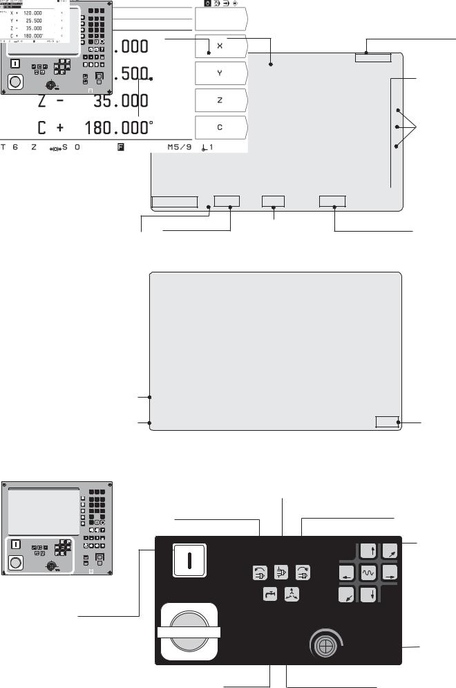
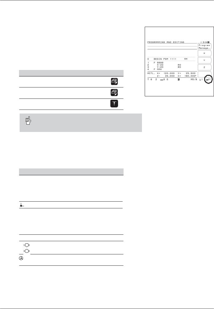
Input line
Tool number  and tool axis
Spindle speed |
Feed rate |
Spindle brake
Operating mode symbols (current mode is highlighted)
Soft-key row (with 5 soft keys)
Soft keys
Selected
 datum Miscellaneous
function M
Screen in the operating modes
PROGRAMMING AND
EDITING and
PROGRAM RUN
Current 
block
Current positions
Status line |
Symbol for |
|
soft-key row |
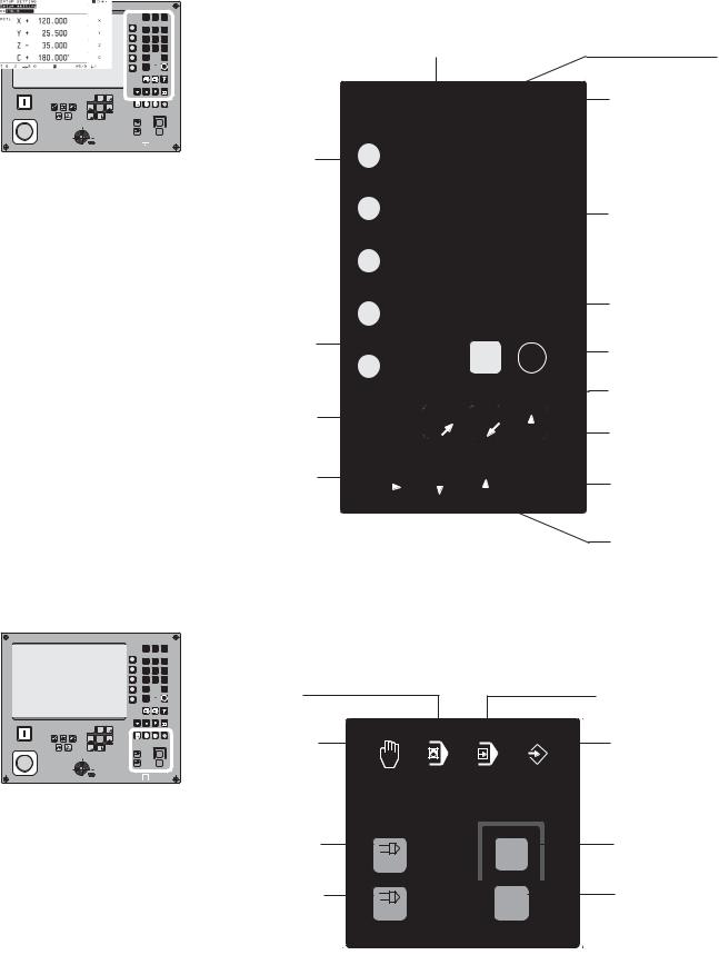
Controlling machine functions
MOD INFO HELP
7 8 9
4 5 6
1 2 3
0  –
–
Spindle brake
Counterclockwise |
Clockwise |
spindle rotation |
spindle rotation |
|
|
CE |
ENT |
|
|
|
|
|
|
GOTO |
´ |
+ |
Machine axis |
X+´ |
Z–´ |
X–´ |
|
|||
|
Y+ |
|
|
|
|
|
Y– |
Z´+ |
I |
NC |
Z– |
Y |
direction keys; |
100 |
150 |
I |
|
|
Rapid traverse |
|
50 |
0 |
NC |
|
|
||
|
|
0 |
X+´ |
X–´ |
key |
|
|
F % |
|
HEIDENHAIN |
– |
´ |
Y |
Z+ |
Power supply |
|
100 |
|
EMERGENCYSTOP |
|
|
|
|
50 |
150 |
Feed rate |
|
|
F % |
override |
Coolant |
Release tool |
|
|
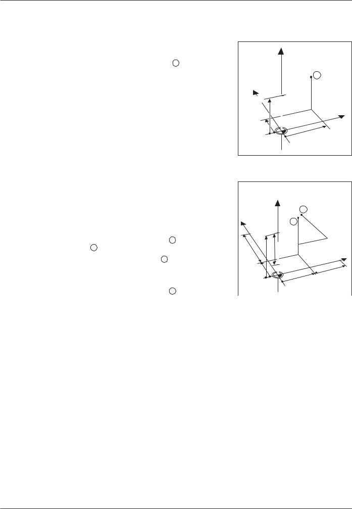
Selecting functions and programming
Z–´  Y+
Y+
X+´  X–´
X–´
Y– Z´+
100
50 |
150 |
|
F % |
MOD INFO HELP
7 8 9
4 5 6
1 2 3
0  –
–
CE  ENT
ENT
GOTO
NC
II
NC
00
 HEIDENHAIN
5 soft keys (functions vary according to associated fields on screen)
Clear entries or error messages
Page through individual soft-key rows
Access program blocks to make changes, or switch operating parameters
Change parameters |
Select or deselect |
||
and settings |
INFO functions |
||
|
|
|
|
MOD INFO HELP
7 8 9
4 5 6
1 2 3
0  –
–
CE |
ENT |
GOTO
Select or deselect HELP screens
Numeric input keys
Change sign
Confirm entry
Incremental dimensions
Return to previous soft-key level
Go to program block or operating parameter
Select programs and program blocks
Selecting operating modes; Start or stop NC and spindle
MOD INFO HELP
7 8 9
4 5 6
1 2 3
0  –
–
CE  ENT
ENT
GOTO
Z–´  Y+
Y+
X+´  X–´
X–´
Y– Z´+
|
I |
NC |
100 |
I |
|
|
0 |
NC |
|
0 |
|
50 |
150 |
|
|
F % |
|
 HEIDENHAIN
POSITIONING WITH |
PROGRAM RUN |
MDI |
|
MANUAL |
PROGRAMMING AND |
OPERATION |
EDITING |
Spindle ON |
NC |
Start NC |
I |
I |
(NC-I key) |
|
||
Spindle OFF |
NC |
Stop NC |
0 |
0 |
|

|
Contents |
|
|
SoftwareVersion ................................................................................................. |
7 |
|
TNC 124.............................................................................................................. |
7 |
|
About This Manual .............................................................................................. |
8 |
|
Special Notes in this Manual .............................................................................. |
9 |
|
TNC Accessories .............................................................................................. |
10 |
1 |
Fundamentals of Positioning ................................................... |
11 |
|
Coordinate system and coordinate axes ........................................................... |
11 |
|
Datums and positions ....................................................................................... |
12 |
|
Machine axis movements and position feedback ............................................... |
14 |
|
Angular positions .............................................................................................. |
15 |
2 |
Working with the TNC 124 – First Steps .................................. |
17 |
|
Before you start ................................................................................................ |
17 |
|
Switch-on .......................................................................................................... |
17 |
|
Operatingmodes .............................................................................................. |
18 |
|
HELP, MOD and INFO functions ....................................................................... |
18 |
|
Selecting soft-key functions .............................................................................. |
19 |
|
Symbols on the TNC screen ............................................................................. |
19 |
|
On-screen operating instructions ....................................................................... |
20 |
|
Error messages ................................................................................................ |
21 |
|
Selecting the unit of measurement .................................................................... |
21 |
|
Selecting position display types ........................................................................ |
22 |
|
Traverse limits ................................................................................................... |
22 |
3 |
Manual Operation and Setup .................................................... |
23 |
|
Feed rate F, spindle speed S and miscellaneous function M ............................. |
23 |
|
Moving the machine axes .................................................................................. |
25 |
|
Entering tool length and radius .......................................................................... |
28 |
|
Calling the tool data .......................................................................................... |
29 |
|
Selecting datum points ..................................................................................... |
30 |
|
Datum setting: Approaching positions and entering actual values ...................... |
31 |
|
Functions for datum setting ............................................................................... |
33 |
|
Measuring diameters and distances .................................................................. |
33 |
4 |
Positioning with Manual Data Input (MDI) ................................ |
38 |
|
Before you machine the workpiece .................................................................... |
38 |
|
Taking the tool radius into account .................................................................... |
38 |
|
Feed rate F, spindle speed S and miscellaneous function M ............................. |
39 |
|
Entering and moving to positions ....................................................................... |
41 |
|
Pecking and tapping ......................................................................................... |
43 |
|
Hole patterns .................................................................................................... |
48 |
|
Bolt hole circle patterns .................................................................................... |
49 |
|
Linear hole patterns .......................................................................................... |
53 |
|
Rectangular pocket milling ................................................................................ |
57 |
5 |
Programming ............................................................................. |
59 |
|
Operating mode PROGRAMMING AND EDITING ............................................. |
59 |
|
Entering a program number ............................................................................... |
60 |
|
Deleting programs............................................................................................. |
60 |
|
Editing programs ............................................................................................... |
61 |
Contents
|
Editing program blocks ..................................................................................... |
62 |
|
Editing existing programs.................................................................................. |
63 |
|
Deleting program blocks ................................................................................... |
64 |
|
Feed rate F, spindle speed S and miscellaneous function M ............................ |
65 |
|
Enteringprogram interruptions .......................................................................... |
67 |
|
Calling the tool data in a program ...................................................................... |
68 |
|
Calling datum points ......................................................................................... |
69 |
|
Entering dwell time ........................................................................................... |
70 |
6 |
Programming Workpiece Positions ......................................... |
71 |
|
Entering workpiece positions ............................................................................ |
71 |
|
Transferring positions: Teach-In mode ............................................................... |
73 |
7 |
Drilling, Milling Cycles and Hole Patterns in Programs .......... |
77 |
|
Entering a cycle call ......................................................................................... |
78 |
|
Drilling cycles in programs ................................................................................ |
78 |
|
Hole patterns in programs ................................................................................. |
85 |
|
Rectangular pockets in programs ...................................................................... |
91 |
8 |
Subprograms and Program Section Repeats ......................... |
94 |
|
Subprograms .................................................................................................... |
95 |
|
Program section repeats ................................................................................... |
97 |
9 |
Transferring Files Over the Data Interface ............................. |
100 |
|
Transferring a program into the TNC ................................................................ |
100 |
|
Reading a program out of the TNC .................................................................. |
101 |
|
Transferring tool tables and datum tables ........................................................ |
102 |
10 |
Executing programs ................................................................ |
103 |
|
Single block .................................................................................................... |
104 |
|
Full sequence ................................................................................................. |
105 |
|
Interruptingprogramrun .................................................................................. |
105 |
11 |
Positioning Non-Controlled Axes........................................... |
106 |
12 Cutting Data Calculator, Stopwatch and |
|
|
|
Pocket Calculator: The INFO Functions ................................ |
107 |
|
Cutting data: Calculate spindle speed S and feed rate F ................................. |
108 |
|
Stopwatch ....................................................................................................... |
109 |
|
Pocket calculator functions ............................................................................. |
109 |
13 User Parameters: The MOD Function .................................... |
111 |
|
|
Entering user parameters ................................................................................ |
111 |
|
TNC 124 user parameters ............................................................................... |
112 |
14 Tables, Overviews and Diagrams ........................................... |
113 |
|
|
Miscellaneous functions (M functions) ............................................................. |
113 |
|
Pin layout and connecting cable for the data interface ..................................... |
115 |
|
Diagram for machining .................................................................................... |
116 |
|
Technicalinformation ...................................................................................... |
117 |
|
Accessories .................................................................................................... |
118 |
Subject Index ........................................................................... |
119 |

Software Version
This User's Manual is for TNC 124 models with the following software version:
Progr. 246 xxx-16.
The x's can be any numbers.
For detailed technical information refer to the Technical
Manual for the TNC 124.
NC and PLC software numbers
The NC and PLC software numbers of your unit are displayed on the TNC screen after switch-on.
Location of use
The TNC complies with the limits for a Class A device in accordance with the specifications in EN 55022, and is intended for use primarily in industrially-zoned areas.
TNC 124
TNC family
What is NC? NC stands for “NumericalControl,” that is, control of a machine tool by means of numbers. Modern controls such as the TNC have a built-in computer for this purpose and are therefore called CNC (Computerized Numerical Control).
From the very beginning, the TNCs from HEIDENHAIN were developed specifically for shop-floor programming by the machinist. This is why they are called TNC, or“TouchNumericalControls.”
The TNC 124 is a straight cut control for boring machines and milling machines with up to three axes. It also features position display of a fourth axis.
Conversational programming
Workpiece machining is defined in a part program. It contains a complete list of instructions for machining a part, for example, the target position coordinates, the feed rate and the spindle speed.
You begin programming each machining step by simply pressing a key or soft key. The TNC then asks for all the information that it needs to execute the step.
|
|
|
TNC 124 |
7 |
|

About This Manual
If you're new to TNC, you can use the operating instructions as a step-by-step workbook. This part begins with a short introduction to the basics of coordinate systems and position feedback, and provides an overview of the available features. Each feature is explained in detail, using an example — so you won't get “lost” too deeply in the theory. As a beginner you should work through all the examples presented.
The examples are intentionally brief; it generally won't take you longer than 10 minutes to enter the example data.
If you're already proficient with TNC, you can use the operating instructions as a comprehensive review and reference guide. The clear layout and the subject index make it easy to find the desired topics.
Dialog flowcharts
Dialog flowcharts are used for each example in this manual.
They are laid out as follows:
The operating mode is indicated above the first dialog flowchart.
This area shows the |
This area shows the key function or work step. |
keys to press. |
If necessary, supplementary information will also be included. |
|
|
Prompt
This area shows the keys to press.
This area shows the key functionor work step.
If necessary, supplementary information will also be included.
If there is an arrow at the end of the flowchart, this means that it continues on the next page.
A prompt appears with some actions (not always) at the top of the screen.
If two flowcharts are divided by abroken line, and words by “or,” this means that you can follow either of the instructions.
Some flowcharts also show the screen that will appear after you press the correct keys.
Abbreviated flowcharts
Abbreviated flowcharts supplement the examples and explanations. An arrow ( ) indicates a new input or a work step.
8 |
TNC 124 |

Special Notes in this Manual
Particularly important information is presented separately in shaded boxes. Be sure to carefully pay attention to these notes. If you ignore these notes your TNC may not function as required, or damage the workpiece or tool.
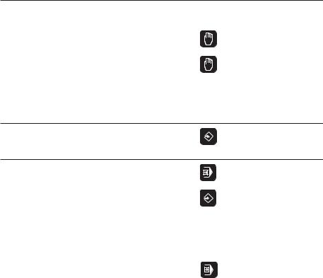
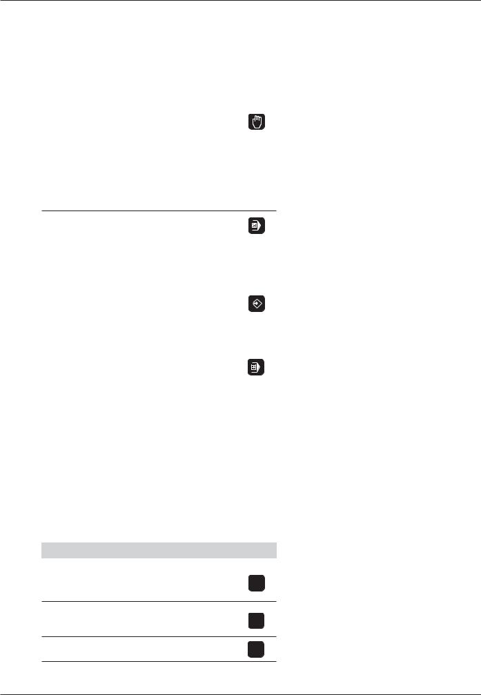
Symbols used in the notes
Each note is identified by a symbol to the left. Your manual uses three different symbols which have the following meanings:
General note,
e.g., indicating the behavior of the control.
Note with reference to themachine manufacturer, e.g., indicating that a specific function must be enabled for your machine tool.
Important note,
e.g., indicating that a special tool is required for the function.
|
|
|
TNC 124 |
9 |
|

TNC Accessories
Electronic handwheel
Electronic handwheels facilitate precise manual control of the axis slides. Like a conventional machine tool, the machine slide moves in direct relation to the rotation of the handwheel. A wide range of traverses per handwheel revolution is available.
The HR 410 Electronic Handwheel
10 |
TNC 124 |
1Fundamentals of Positioning
1
Fundamentals of Positioning
Coordinate system and coordinate axes
Reference system
In order to define positions on a surface, a reference system is required. For example, positions on the earth's surface can be defined “absolutely” by their geographic coordinates of longitude and latitude. The termcoordinate comes from the Latin word for “that which is arranged.” In contrast to the relative definition of a position that is referenced to a known location, the network of horizontal and vertical lines on the globe constitutes an absolute reference system.
The Greenwich observatory illustrated in Fig. 1.1 is located at 0° longitude, and the equator at 0° latitude.
Cartesian coordinate system
On a TNC-controlled milling or drilling machine tool, workpieces are normally machined according to a workpiece-based Cartesian coordinate system (a rectangular coordinate system named after the French mathematician and philosopher Renatus Cartesius, who lived from 1596 to 1650). The Cartesian coordinate system is based on three coordinate axes designated X, Y and Z which are parallel to the machine guideways.
The figure to the right illustrates the “right-hand rule” for remembering the three axis directions: the middle finger is pointing in the positive direction of the tool axis from the workpiece toward the tool (the Z axis), the thumb is pointing in the positive X direction, and the index finger in the positive Y direction.
Axis designations
X, Y and Z are the main axes of the Cartesian coordinate system. The additional axes U, V and W are secondary linear axes parallel to the main axes. Rotary axes are designated as A, B and C (see Fig. 1.3).
60°
Greenwich
30°
0°
30°
60°
90° 0° 90°
Fig. 1.1: The geographic coordinate system is an absolute reference system
+Y |
+Z |
+X |
|
|
+Z |
|
+X |
|
+Y |
Fig. 1.2: Designations and directions of the axes on a milling machine
|
Z |
Y |
|
|
|
W+ |
C+ |
B+ |
|
||
|
|
V+ |
|
|
A+ |
|
|
X |
|
|
U+ |
Fig. 1.3: Main, additional and rotary axes in the Cartesian coordinate system
TNC 124 |
11 |

1Fundamentals of Positioning
Datums and positions
Setting the datum
The workpiece drawing identifies a certain point on the workpiece (usually a corner) as the “absolute datum” and perhaps one or more other points as relative datums. The datum setting procedure establishes these points as the origin of the absolute or relative coordinate systems: The workpiece, which is aligned with the machine axes, is moved to a certain position relative to the tool and the display is set either to zero or to another appropriate value (e.g., to compensate the tool radius).
Example: Coordinates of hole 1 :
X = |
10 |
mm |
Y = |
5 |
mm |
Z = |
0 |
mm (hole depth: Z = – 5 mm) |
The datum of the Cartesian coordinate system is located 10 mm from hole 1 on the X axis and 5 mm from it in the Y axis (in negative direction).
The TNC's probing functions facilitate finding and setting datums.
Z |
Y |
X |
Fig. 1.4: The workpiece datum represents the origin of the Cartesian coordinate system
Z |
Y |
X |
1 |
5 |
10 |
Fig. 1.5: Hole 1 defines the coordinate system
12 |
TNC 124 |
1Fundamentals of Positioning Datums and Positions
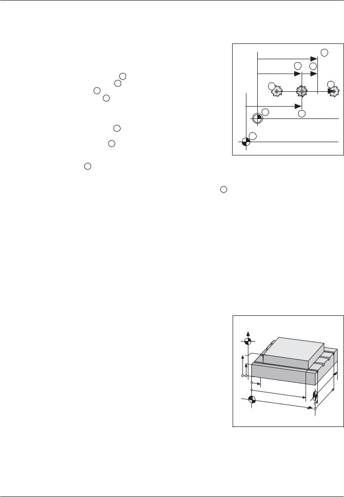
Absolute workpiece positions
Each position on the workpiece is uniquely identified by its absolute coordinates.
Example: Absolute coordinates of the position 1 :
X= 20 mm
Y= 10 mm
Z= 15 mm
If you are drilling or milling a workpiece according to a workpiece drawing with absolute coordinates, you are moving the tooltothe value of the coordinates.
|
Z |
|
|
|
|
|
|
1 |
|
Y |
|
|
|
|
15 |
|
Z=15mm |
|
|
|
|
Y=10mm |
X |
|
|
X=20mm |
|
||
|
|
|
||
|
|
|
|
|
10 |
|
|
|
|
|
|
|
|
20 |
Fig. 1.6: Position definition through absolute
coordinates
Incremental workpiece positions
A position can also be referenced to the preceding nominal position. In this case the relative datum is always the last programmed position. Such coordinates are referred to as incremental coordinates (increment = increase). They are also called incremental or chain dimensions (since the positions are defined as a chain of dimensions). Incremental coordinates are designated with the prefixI.
Example: Incrementalcoordinatesofposition 3 referencedto position 2
Absolute coordinates of position 2 :
X= 10 mm
Y = 5 mm
Z= 20 mm
Incremental coordinates of position 3 :
IX = 10 mm
IY = 10 mm
IZ = –15 mm
|
|
3 |
|
Y |
|
|
I |
|
15mm–Z=I |
Y |
|
2 |
= |
||
1 |
|||
|
0 |
||
|
|
m |
|
|
|
m |
|
|
20 |
IX=10mm |
|
|
|
||
|
|
|
|
10 |
15 |
|
X |
|
|
||
|
|
|
|
5 |
5 |
|
10 |
|
|
|
|
|
0 |
|
10 |
|
|
|
|
|
0 |
|
|
Fig. 1.7: Position definition through incremental coordinates
If you are drilling or milling a workpiece according to a drawing with incremental coordinates, you are moving the toolbythe value of the coordinates.
TNC 124 |
13 |
1Fundamentals of Positioning
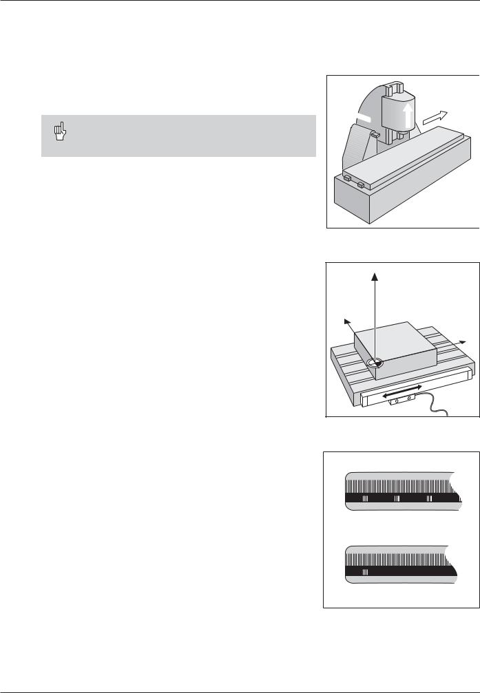
Machine axis movements and position feedback
Programming tool movements
During workpiece machining, an axis position is changed either by moving the tool or by moving the machine table on which the workpiece is fixed.
When entering tool movements in a part program you always program as if the tool is moving and the workpiece is stationary.
+Y
 +Z
+Z
+X
Position feedback
The position feedback encoders — linear encoders for linear axes, angle encoders for rotary axes — convert the movement of the machine axes into electrical signals. The control evaluates these signals and constantly calculates the actual position of the machine axes.
If there is an interruption in power, the calculated position will no longer correspond to the actual position. When power is restored, the TNC can re-establish this relationship.
Reference marks
The scales of the position encoders contain one or more reference marks. When a reference mark is passed over, it generates a signal which identifies that position as the reference point (scale reference point = machine reference point). With the aid of this reference mark the TNC can re-establish the assignment of displayed values to machine axis positions.
If the position encoders featuredistance-coded reference marks, each axis need only move a maximum of 20 mm (0.8 in.) for linear encoders, and 20° for angle encoders.
Fig. 1.8: On this machine the tool moves in the Y and Z axes; the workpiece moves in the X axis.
Z |
Y |
X |
Fig. 1.9: Linear position encoder, here for the X axis
Fig. 1.10: Linear scales: above with distancecoded reference marks, below with one reference mark
14 |
TNC 124 |

1Fundamentals of Positioning
Angular positions |
|
|
|
For angular positions, the following reference axes are defined: |
|
||
Plane |
Angle reference axis |
Y |
|
|
|||
X / Y |
+ X |
–270° |
|
Y / Z |
+ Y |
||
+45° |
|||
Z / X |
+ Z |
||
+180° |
|||
|
|
X |
|
Algebraic sign for direction of rotation |
–180° |
||
|
|||
Positive direction of rotation is counterclockwise if the working plane |
|
||
is viewed in negative tool axis direction (see Fig. 1.11). |
|
||
Example: Angle in the working plane X / Y |
|
||
|
|
Fig. 1.11: Angle and the angle reference |
|
Angle |
Corresponds to the ... |
||
axis, here in the X / Y plane |
|||
+ 45° |
... bisecting line between +X and +Y |
|
|
|
|
|
|
± 180° |
... negative X axis |
|
|
|
|
|
|
– 270° |
... positive Y axis |
|
|
|
|
|
TNC 124 |
15 |

1Fundamentals of Positioning
NOTES
16 |
TNC 124 |
2Working with the TNC 124 – First Steps
2
Working with the TNC 124 – First Steps
Before you start
You must cross over the reference marks after every switch-on. From the positions of the reference marks, the TNC automatically reestablishes the relationship between axis slide positions and display values that you last defined by setting the datum.
Setting up a new datum point automatically stores the new relationship between axis positions and display values.
Switch-on
0 1 |
Switch on the TNC and the machine tool. |
|
M E M O R Y |
T E S T |
|
Please wait... |
|
The internal memory of the TNC is checked automatically. |
|
|
|
P O W E R I N T E R R U P T E D |
||
|
Clear the TNC message indicating that the power was interrupted. |
|
CE |
|
|
|
|
|
R E L A Y E X T. D C V O L T A G E M I S S I N G
Switch on the control voltage.
The TNC automatically checks the function of the EMERGENCY STOP button.
C R O S S O V E R R E F E R E N C E M A R K S
For each axis: NC
or
Press and hold successively:
X+´
Y+
Z´+
Movetheaxesinthedisplayedsequenceacrossthereferencemarks.
or
Cross the reference marks in any sequence:
Press the machine axis direction button until the moving axis disappears from the screen.
Sequence in this example: X AXIS, Y AXIS, Z AXIS
The TNC 124 is now ready for operation in the
MANUAL OPERATION mode.
TNC 124 |
17 |
2Working with the TNC 124 – First Steps
Operating modes
Selecting the operating mode determines which functions are available to you.
Available functions |
Mode |
Key |
Move the machine axes |
MANUAL |
|
• with the direction keys, |
OPERATION |
|
•with the electronic handwheel,
•by incremental jog positioning; Datum setting —
also with probing functions (e.g. circle center as datum);
Enter and change spindle speed and miscellaneous functions
Enter positioning blocks and |
POSITIONING |
|
execute them block by block; |
WITH |
|
Enter hole patterns and |
MDI |
|
execute them block by block; |
|
|
Change spindle speed, feed |
|
|
rate, miscellaneous functions; |
|
|
Enter tool data; |
|
|
|
|
|
Store work steps for small-lot |
PROGRAMMING |
|
production by |
AND EDITING |
|
• |
Keyboard entry |
|
• |
Teach-in; |
|
Transferring programs |
|
|
through the data interface |
|
|
|
|
|
Executing programs |
PROGRAM |
|
• |
continuously |
RUN |
• |
blockwise |
|
|
|
|
You can switch to another operating mode at any time by pressing the key for the desired mode.
HELP, MOD and INFO functions
You can call the HELP, MOD and INFO functions at any time.
To call a function:
Press the function key for that function.
To leave a function:
Press the same function key again.
Functions |
Designation |
Key |
|
|
|
On-screen operating |
HELP |
|
instructions: |
|
|
graphics and text explaining |
|
HELP |
the current screen contents |
|
|
User parameters: |
MOD |
To redefine the TNC's basic |
|
operating characteristics |
|
MOD
Cutting data calculator, |
INFO |
stopwatch, pocket calculator |
|
INFO
18 |
TNC 124 |
2Working with the TNC 124 – First Steps
Selecting soft-key functions
The soft-key functions are grouped into one or more rows. The TNC indicates the number of rows by a symbol at the bottom right of the screen.
If no symbol is visible, that means that all pertinent functions are already shown. The highlighted rectangle in the symbol indicates the currentrow.
Overview of functions
Function Key
Page through the soft-key rows: forwards
Page through the soft-key rows: backwards
Go back one soft-key level
Fig. 2.1: The symbol for soft-key rows at the bottom right of the screen. Here, the first row is being displayed.
The TNC displays the soft keys with the main functions of an operating mode whenever you press the key for that mode.
Symbols on the TNC screen
The TNC continuously informs you of the current operating status. The symbols are displayed on the screen
•next to the designations of the coordinate axes or
•in the status line at the bottom of the screen.
Symbol
T ...
S ... *)
F ... *)
M ...
...
ACTL.
NOML.
REF
LAG
* |
® |
|
® |
||
|
||
® |
® |
Function/Meaning
Tool, for example T 1
Spindle speed, e.g. S 1000 [rpm] Feed rate, e.g. F 200 [mm/min] Miscellaneous function, e.g. M 3
Datum, e.g.:  1
1
TNC displays actual values TNC displays nominal values
TNC displays the reference position TNC displays the servo lag
Control active
Spindle brake active
Spindle brake inactive
Axis can be moved with the electronic handwheel
*) A highlighted F or S symbol means that the feed rate or spindle has not been enabled by the PLC.
TNC 124 |
19 |

2Working with the TNC 124 – First Steps
On-screen operating instructions
The integrated operating instructions provide information and assistance in any situation.
To call the operating instructions:
Press the HELP key.
Use the paging keys if the explanation extends over more than one screen page.
To leave the operating instructions:Press the HELP key again.
Example: On-screen operating instructions for datum setting
(PROBE CENTERLINE)
The PROBE CENTERLINE function is described in this manual on page 34.
Select the MANUAL OPERATIONmode.
Press the paging key to display the second screen page.
Press the HELP key.
The first page of the operating instructions for the probing functions appears.
Page reference at the lower right of the screen:
the number in front of the slash is the current page, the number behind the slash is the total number of pages.
The on-screen operating instructions now contain the following information on PROBING FUNCTIONS (on three pages):
•Overview of the probing functions (page 1)
•Graphic illustration of all probing functions (pages 2 and 3)
To leave the operating instructions: Press HELP again.
The screen returns to the menu for the probing functions.
Press (for example) the soft key Centerline.
Press HELP.
The screen now displays operating instructions — spread over three pages — on the function PROBE CENTERLINE including:
•Overview of all work steps (page 1)
•Graphic illustration of the probing sequence (page 2)
•Information on how the TNC reacts and on datum setting (page 3)
To leave the on-screen operating instructions: Press HELP again.
Fig. 2.2: On-screen operating instructions for PROBE, page 1
Fig. 2.3: On-screen operating instructions
for PROBE CENTERLINE, page 1
Fig. 2.4: On-screen operating instructions
for PROBE CENTERLINE, page 2
20 |
TNC 124 |
2Working with the TNC 124 – First Steps
Error messages
If an error occurs while you are working with the TNC, a message will come up on the screen.
To call an explanation of the error:
Press the HELP key.
To clear the error message:Press the CE key.
Blinking error messages
W A R N I N G !
Blinking error messages mean that the operational reliability of the TNC has been impaired.
If a blinking error message occurs:
Note down the error message displayed on the screen.
Switch off the TNC and machine tool.
Attempt to correct the problem with the power off.
If the error cannot be corrected or if the blinking error message recurs, notify your customer service agency.
Selecting the unit of measurement
Positions can be displayed in millimeters or inches. If you choose inches, inch will be displayed at the top of the screen.
To change the unit of measurement:
Press MOD.
Page to the soft-key row containing the user parameter mm or inch.
Choose the soft key mm or inch to change to the other unit.
Press MOD again.
For more information on user parameters, see Chapter 13.
Fig. 2.5: The inch indicator
TNC 124 |
21 |
2Working with the TNC 124 – First Steps
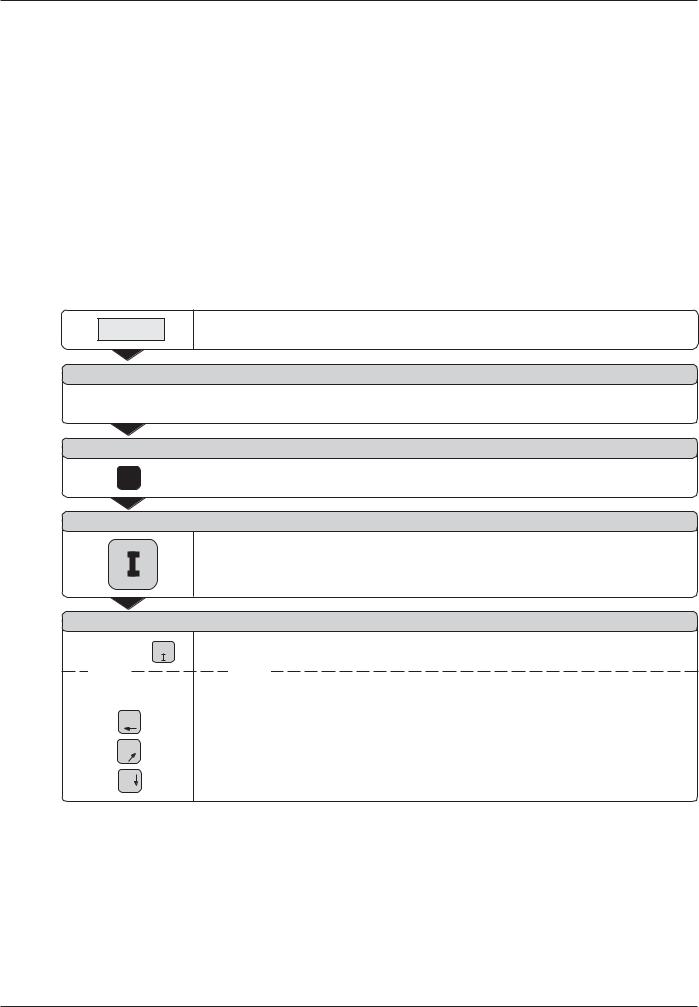
Selecting position display types
The TNC can display various position values for a specific tool position.
The positions indicated in Fig. 2.6 are:
•Starting position of the tool A
•Target position of the tool Z
•Workpiecedatum W
•Scalereferencepoint M
The TNC position display can be set to show the following types of information:
•Nominal position NOML. 1
The value presently commanded by the TNC.
•Actual position ACTL. 2
The position at which the tool is presently located as referenced to the workpiece datum.
•Servo lag LAG 3
The difference between nominal and actual positions (NOML. – ACTL.)
•Actual position as referenced to the scale reference point REF 4
|
1 |
2 |
3 |
A |
Z |
|
|
W |
4 |
M |
|
Fig. 2.6: Tool and workpiece positions
To change the position display
Press MOD.
Page to the soft-key row containing the user parameter
Posit.
Press the soft key for selecting the position display type and change to the other display type.
Select the desired display type.
Press MOD again.
For more information on user parameters, see Chapter 13.
Traverse limits
The maximum range of traverse of the machine axes is set by the machine manufacturer.
Z |
|
|
|
Zmax |
|
|
|
Zmin |
|
|
Y |
|
|
|
|
X |
|
Y |
|
min |
X |
max |
|
|
max |
||
|
|
||
|
|
|
|
|
|
Y |
|
|
|
min |
|
|
|
X |
|
Fig. 2.7: Traverse limits define the machine's actual working envelope
22 |
TNC 124 |
3Manual Operation and Setup
3
Manual Operation and Setup
The machine manufacturer may define a method of moving the axes that varies from what is described in this manual.
On the TNC 124 you can move the machine axes with:
•the direction keys,
•the electronic handwheel,
•incremental jog positioning, or
•positioning with manual data input MDI (see Chapter 4).
In the MANUAL OPERATION and POSITIONING WITH MDI modes of operation (see Chapter 4) you can also enter and change:
•Feed rate F (the feed rate can only be entered in
POSITIONING WITH MDI)
•Spindle speed S
•Miscellaneous function M
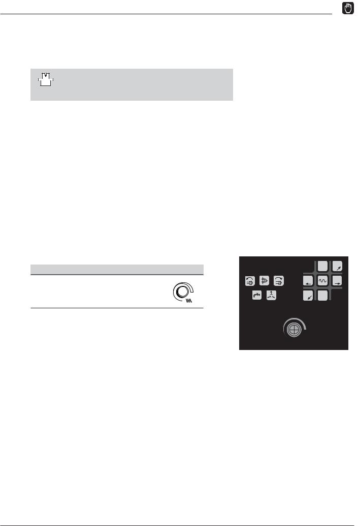
Feed rate F, spindle speed S and miscellaneous function M
To change the feed rate F:
You can vary the feed rate F infinitely by turning the knob for feed rate override on the TNC control panel.
Feed rate override
You can vary the feed rate F from |
100 |
0% to 150% of the set value |
|
50 |
150 |
|
F % |
|
0 |
Z–´  Y+
Y+
X+´ |
X–´ |
Y– Z´+
100
50 |
150 |
F %
Fig. 3.1: Feed rate override on the TNC control panel
TNC 124 |
23 |

3Manual Operation and Setup
Feed Rate F, Spindle Speed S and Miscellaneous Function M
Entering and changing the spindle speed S
The machine manufacturer determines which spindle speeds are allowed on your TNC.
Example: Entering the spindle speed S
|
SelectS for the spindle speed function. |
S p i n d l e s p e e d ? |
|
9 5 0 |
Enter the spindle speed, for example 950 rpm. |
NC |
Change the spindle speed. |
To change the spindle speed S:
You can vary the spindle speed S infinitely by turning the knob for spindle speed override—if provided—on the TNC control panel.
Spindle speed override
You can vary the spindle speed S from 0% to 150% of the set value
100
50 |
150 |
 S %
S %
0
Entering a miscellaneous function M
The machine manufacturer determines which miscellaneous functions are available on your TNC and which effects they have.
Example: Entering a miscellaneous function
|
|
|
|
|
Select M for miscellaneous function. |
|
|
|
|
|
|
|
|
|
M i s c e l l a n e o u s f u n c t i o n M ? |
||
3 |
|
Enter the miscellaneous function, for example M 3: spindle ON, clockwise. |
|||
|
|||||
|
|
|
|
|
|
|
|
|
|
|
|
NC |
|
Execute the miscellaneous function. |
|||
|
|
|
|
|
|
|
|
|
|
|
|
24 |
TNC 124 |

3Manual Operation and Setup
Moving the machine axes
The TNC control panel includes six direction keys. The keys for the X and Y axes are identified with a prime mark (X', Y'). This means that the traversing directions indicated on these keys correspond to movement of the machine table.
Traversing with the direction keys
The direction key defines at the same time
•the coordinate axis, for example X
•the traversing direction, for example negative: X–
On machine tools with central drives you can only move one axis at a time.
If you are moving a machine axis with the direction key, the TNC automatically stops moving the axis as soon as you release the key.
For continuous movement:
You can also move the machine axes continuously: The axis continues to move after you release the key.
To stop the axis press the key indicated below in example 2.
Rapid traverse
To move an axis at rapid traverse:
Press the rapid traverse key and the direction key together.
Example: Moving the machine axis in the Z+ direction with the direction key (retract tool):
Example 1: Moving the machine axes
Operating mode: MANUAL OPERATION
Z–´  Y+
Y+
´ |
´ |
X+ |
X– |
Y– Z´+
Fig. 3.2: The direction keys on the TNC control panel, with the key for rapid traverse in the center
Z 
Y

 X
X
|
´ |
|
|
Press the direction key, here for the positive Z direction (Z'+) and hold it |
Press and hold: |
Z+ |
|
|
as long as you wish the axis to move. |
|
||||
|
|
|
|
|
|
|
|
|
|
Example 2: For continuous movement of the machine axes
Operating mode: MANUAL OPERATION
|
´ |
|
NC |
Start movement of the axis: Press the direction key, here for the positive |
|
|
|
||||
|
|
|
|||
Together: |
Z+ |
|
|
|
Z direction (Z'+) together with the NC-I key. |
|
NC |
|
|
|
|
|
|
|
|
||
|
|
|
|
Stop the axis. |
|
|
|
|
|
||
|
0 |
|
|
|
|
|
|
|
|
|
|
TNC 124 |
25 |

3Manual Operation and Setup Moving the Machine Axes
Traversing with the electronic handwheel
Electronic handwheels can be connected only to machines with preloaded drives. The machine manufacturer can tell you whether electronic handwheels can be connected on your machine.
You can connect the following HEIDENHAIN electronic handwheels to your TNC 124:
•HR 410 portable handwheel
•HR 130 integral handwheel
Direction of traverse
The machine manufacturer determines in which direction the handwheel must be turned to move an axis in a specific direction.
If you are working with the HR 410 portable handwheel
The HR 410 portable handwheel is equipped with two permissive buttons . You can move the machine axes with the handwheel only if a permissive button is depressed.
Other features of the HR 410:
•Axis selection keys X, Y and Z .
•The axes can be moved continuously with the + and – direction keys .
•Three keys for slow, medium and fast traverse .
•Actual-position-capture key for transferring positions or tool data in teach-in mode directly from the position display into the program or tool table (without having to type the numbers).
•Three keys for machine functions defined by the machine tool builder.
•EMERGENCY STOP button for immediate machine shutdown in case of danger. This safety feature is additional to the permissivebuttons.
•Magnetic holding pads on the back of the handwheel enable you to place it within easy reach on a flat metal surface.
Example: Moving a machine axis with the HR 410 electronic handwheel, for example the Y axis
1
2
3
4
XIV
Y |
V |
5 |
Z
6
7
–+
8
FCT |
FCT |
FCT |
A |
B |
C |
Fig. 3.3: The HR 410 portable electronic handwheel
Operating mode:
Y
MANUAL MODE
Select the Electronic handwheel function.
The handwheel symbol is displayed next to the “X” for the X coordinate.
Select the coordinate axis at the handwheel.
The handwheel symbol is shifted to the selected coordinate axis.
Select the traverse per revolution: large, medium, or small, as preset by the machine tool builder.
Press the permissive button! Turn the handwheel to move the machine axis.
26 |
TNC 124 |

3Manual Operation and Setup Moving the Machine Axes
Incremental jog positioning
Incremental jog positioning enables you to move a machine axis by the increment you have preset each time you press the corresponding direction key.
Current jog increment
If you enter a jog increment, the TNC stores the entered value and displays it right of the highlighted input line for Infeed.
The programmed jog increment is effective until a new value is entered by keyboard or soft key.
Maximum input value
0.001 mm£ jog increment£ 99.999 mm
Changing the feed rate F
You can increase or decrease the feed rate F by turning the knob for feedrateoverride.
Fig. 3.4: TNC screen for incremental jog positioning
Example: Moving the machine axis in the X+ direction by incremental |
|
|
|
jog positioning |
Z |
|
|
|
|
|
|
|
5 |
5 |
|
|
5 |
10 |
X |
Operating mode: MANUAL OPERATION |
|
|
|
Select the |
Jog Increm. function. |
|
|
I n f e e d :
0 . 0 0 0
Enter the infeed (5 mm)—by soft key.
|
|
|
|
|
|
|
|
|
|
|
|
|
|
|
|
|
|
|
|
|
|
|
|
|
|
|
|
|
|
|
|
|
|
|
|
|
|
|
|
|
|
|
|
|
|
|
|
|
|
|
|
|
|
|
|
|
|
|
|
|
|
or |
|
|
|
|
|
|
|
|
|
|
|
or |
|
|
|
|
|
|
|
|
|
|
|
|
|
|
|
|
|
|
|
|
|
|
|
|
|
|
|
|
|
|
|
|
|
|
|
|
|
|
|
|
|
|
|
|
|
|
|
|
|
|
|
|
|
|
|
|
|
|
|
|
|
|
|
|
|
|
|
|
|
|
|
|
|
|
|
|
|
|
|
||||||||||||||||||||||||||||||||
|
|
|
|
|
|
|
|
|
Enter the infeed (5 mm)—with the keyboard and confirm your entry with ENT. |
||||||||||||||||||||||||||||||||||||||||||||||||||||
5 ENT |
|
|
|
|
|
|
|
||||||||||||||||||||||||||||||||||||||||||||||||||||||
I n f e e d 0 . 0
X+´
: |
|
0 0 |
5 . 0 0 0 |
Move the machine axis by the entered infeed, for example in the X+direction.
TNC 124 |
27 |

3Manual Operation and Setup
MOD
Entering tool length and radius
Enter the lengths and radii of your tools in the TNC's tool table. The TNC will then take the entered data into account for datum setting and all other machining processes.
You can enter up to 99 tools.
The tool length is the difference in lengthDL between the tool and the zero tool.
To enter the tool length directly move the tool until it touches the workpiece and transfer the tool position coordinate by using the “actual position capture” function.
Sign for the length difference DL
If the tool is longer than the zero tool: DL > 0 If the tool is shorter than the zero tool: DL < 0
Z |
|
|
T1 |
T2 |
T3 |
R1 |
R2 |
R3 |
|
|
∆L3<0 |
∆L1=0 |
|
X |
|
∆L2>0 |
Fig. 3.5: Tool length and radius
Example: Entering the tool length and radius |
|
|
into the tool table |
Z |
|
|
|
|
Tool number: |
e.g. 7 |
|
Tool length: |
T0 |
T7 |
L = 12 mm |
|
|
Tool radius: |
R = 8 mm |
R7 |
 X
X
L0=0 |
L7>0 |
MOD |
Select the user parameters. |
/ |
Go to the soft-key row containing Tool Table. |
|
Open the tool table. |
T o o l
7ENT
T o o l
1 2 ENT
or
or
n u m b e r ?
Enter the tool number (such as 7) and confirm your entry with ENT.
l e n g t h ?
Enter the tool length (12 mm) and confirm your entry with ENT.
or
Capture the actual position in the tool axis by pressing the soft key.
or
Capture the actual position in the tool axis by pressing key on the handwheel.
28 |
TNC 124 |
3Manual Operation and Setup
MOD
T o o l r a d i u s ?
8 ENT |
Enter the tool radius (8 mm) and confirm your entry with ENT. |
MOD
Depart the user parameters.
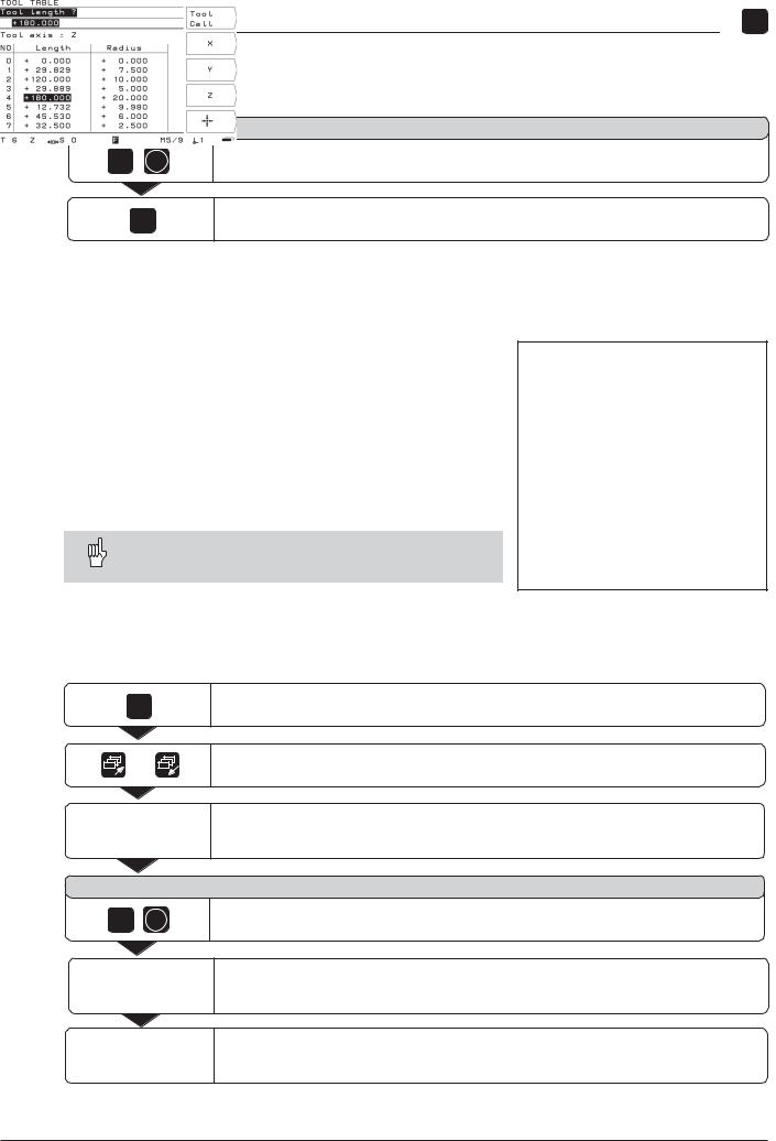
Calling the tool data
The lengths and radii of your tools must first be entered into the TNC's tool table (see previous page).
Before you start workpiece machining, select the tool you are using from the tool table. To call the desired tool, move the highlight to the tool, select the axis with the corresponding soft key and press the soft key Tool Table.
The TNC then takes into account the stored tool data when you work with tool compensation (e.g., with hole patterns).
You can also call the tool data with the command
TOOL CALL in a program.
Fig. 3.6: The tool table on the TNC screen
Example: Calling the tool data |
|
MOD |
Select the user parameters. |
/ |
Go to the first soft-key row containing Tool Table. |
|
Select the tool table. |
T o o l n u m b e r ?
5 |
ENT |
Enter the tool number (here: 5) and confirm your entry with ENT. |
|
|
Select the Tool axis (Z).
“Activate” the tool and depart the user parameters.
TNC 124 |
29 |

3 Manual Operation and Setup
MOD
Selecting datum points
The TNC 124 can store up to 99 datum points in a datum table. In most cases this will free you from having to calculate the axis travel when working with complicated workpiece drawings containing several datums, or when several workpieces are clamped to the machine table at the same time.
For each datum point, the datum table contains the positions that the TNC 124 assigned to the reference point on the scale of each axis (REF values) during datum setting. Note that if you change the REF values in the table, this will move the datum point.
The TNC 124 displays the number of the current datum at the lower right of the screen.
To select the datum:
In all operating modes:
Press MOD and go to the soft key row containing
Datum Table.
Choose the soft key Datum Table.
Select the datum you are using from the datum table.
Leave the datum table: Press MOD again.
In the MANUAL OPERATION and POSITIONING WITH MDI modes of operation:
Press the vertical arrow keys.
The machine manufacturer determines whether “quick datum selection” via arrow keys is enabled on your TNC.
In the PROGRAMMING AND EDITING / PROGRAM RUN modes of operation:
You can also select a datum point by entering the command “DATUM”inaprogram.
30 |
TNC 124 |
 Loading...