


AADvance
The Next Step in Automation
AADvance Controller
Safety Manual
ISSUE: 10_C
DOCUMENT: 553630
ICSTT-RM446K-EN-P

Safety Manual (AADvance Controller)
Notice
In no event will Rockwell Automation be responsible or liable for indirect or consequential damages resulting from the use or application of this equipment. The examples given in this manual are included solely for illustrative purposes. Because of the many variables and requirements associated with any particular installation, Rockwell Automation does not assume responsibility or reliability for actual use based on the examples and diagrams.
No patent liability is assumed by Rockwell Automation, with respect to use of information, circuits, equipment, or software described in this manual.
All trademarks are acknowledged.
Disclaimer
It is not intended that the information in this publication covers every possible detail about the construction, operation, or maintenance of a control system installation. You should refer to your own (or supplied) system safety manual, installation instructions and operator/maintenance manuals.
Revision and Updating Policy
This document is based on information available at the time of its publication; however, the document contents are subject to change from time to time. You should contact Rockwell Automation Technical Support by e-mail — icstsupport@ra.rockwell.com to check if you have the latest version of this publication.
© Copyright Notice, Rockwell Automation 2012
This document contains proprietary information that is protected by copyright. All rights are reserved.
Documentation Feedback
Your comments will help us to serve your documentation needs better. If you discover any errors or have any suggestions on how to improve this publication send your comments to our product support group: icstsupport@ra.rockwell.com
This Safety Manual applies to AADvance Release: 1.3.
ii |
Document: 553630 |
|
ICSTT-RM446K-EN-P Issue: 10_C |

Notes and Symbols used in this manual
This symbol calls attention to items which "must" be considered and implemented when designing and building an AADvance controller for use in a Safety Instrumented Function (SIF). It appears extensively in the AADvance Safety Manual.
Note: Notes are used extensively to provide important information about the product.
Standard Warnings and Cautions
WARNING ELECTRICAL ARCS AND EXPLOSION RISK IN HAZARDOUS AREAS
If you connect or disconnect wiring, modules or communications cabling while power is applied, an electrical arc can occur. This could cause an explosion in hazardous location installations. Do not remove wiring, fuses, modules or communications cabling while circuit is energized unless area is known to be non hazardous.
Failure to follow these instructions may result in personal injury.
WARNING MAINTENANCE
Maintenance must be carried out by people who are experienced in working on electronic equipment and in particular safety related systems.They should have knowledge and experience of local operating and safety standards. Failure to follow these recommendations may result in situations that can lead system damage and even personal injury.
CAUTION RADIO FREQUENCY INTERFERENCE
Most electronic equipment is influenced by Radio Frequency Interference. Caution should be exercised with regard to the use of portable communications equipment around such equipment. Signs should be posted in the vicinity of the equipment cautioning against the use of portable communications equipment.
CAUTION HEAT DISSIPATION AND ENCLOSURE POSITION
System and field power consumption by modules and termination assemblies is dissipated as heat. You should consider this heat dissipation on the design and positioning of your enclosure; e.g. enclosures exposed to continuous sunlight will have a higher internal temperature that could affect the operating temperature of the modules. Modules operating at the extremes of the temperature band for a continuous period can have a reduced reliability.
Document: 553630 |
iii |
ICSTT-RM446K-EN-P Issue: 10_C |
|

Safety Manual (AADvance Controller)
Issue Record
Issue |
Date |
Comments |
01 |
Jan 2009 |
First Issue |
|
|
|
02 |
April 2009 |
Reformat to match associated product user manuals |
03 |
Aug 2009 |
QA review updates |
|
|
|
04 |
Sept 2009 |
Release 1.1 for TUV approval |
05 |
Oct 2009 |
TUV approval release |
|
|
|
06 |
Jan 2010 |
Update for TUV review and comments |
|
|
|
07 |
Feb 2010 |
Update for TUV review additional comments |
|
|
|
08 |
Nov 2010 |
Update for SIL2 and SIL configurations change, MTTR change, |
|
|
UL requirements, Check lists change, peer review comments. |
09* |
March 2011 |
Updates for release R1.2 |
|
|
|
10 |
July 2012 |
Updates for Release 1.3 and 1.3.1 |
10_A |
Aug 2012 |
Updated for additional information about the Analogue Output |
|
|
|
|
|
Module |
10_B |
June 2013 |
Draft issue for release 1.3 incorporating changes following TUV |
|
|
|
|
|
review comments., Also added specifications for electrostatic |
|
|
discharge. |
|
|
|
10_C |
July 2013 |
Update after peer review |
|
|
|
|
|
|
|
|
* Previously Issue 1.2 |
iv |
Document: 553630 |
|
ICSTT-RM446K-EN-P Issue: 10_C |

SUMMARY OF CHANGES
Table 1: |
Issue 10_B to 10_C |
|
|
|
|
Topic |
|
Page |
Added Summary of Changes table to front pages |
v |
|
Re-instatement about ―Modules are for use in an area of not more than pollution |
1-11 |
|
degree 2 in accordance with IEC60664-1‖. |
|
|
|
|
|
Sentence about replacing input modules removed from the Analogue Output |
3-4 |
|
Module |
2nd bullet point. |
|
Added statement about unlocking the module (3rd bullet point) |
4-31 |
|
Added statement about ―not certified for use in zone 1 and Zone 0 |
4-45 |
|
location/environment‖. |
|
|
|
|
|
|
|
|
|
|
|
|
|
|
|
|
|
|
|
|
|
|
|
|
|
|
|
|
|
|
|
|
Document: 553630 |
v |
ICSTT-RM446K-EN-P Issue: 10_C |
|

Safety Manual (AADvance Controller)
Foreword
This technical manual defines how to safely apply AADvance controllers for a Safety Instrument Function. It sets out standards (which are mandatory) and makes recommendations to ensure that installations meet their required safety integrity level. To do this, it addresses how such installations are designed, built, tested, installed and commissioned, operated, maintained and decommissioned. It defines the requirements to be met during the life-cycle stages of safety-related systems design and commissioning so the safety objectives of the system are achieved during operation.
There are requirements for quality systems, documentation and competency in this technical manual; these are additional requirements for an operating company's or integrator's quality systems, procedures and practices.
Note: The AADvance controller is a logic solver. It uses processor modules and I/O modules. An AADvance system is formed by one or more controllers, their power sources, communications networks and workstations.
Who Should Use this Manual
This manual is intended primarily for System Integrators. The information contained in this manual is intended to be used in conjunction with (and not as a substitute for) expertise and experience in safety-related systems. In particular, it is expected that the reader has a thorough understanding of the intended application and safety system principles and can understand the generic terms used within this manual and the terminology specific to the integrator's or project's application area.
Note: The System Integrator remains responsible for the generation of procedures and practices applicable to its business, and shall ensure that these are in accordance with the requirements defined herein. The application of such procedures and practices is also the responsibility of the system integrator, and these are mandatory for systems used for SIL3 applications.
vi |
Document: 553630 |
|
ICSTT-RM446K-EN-P Issue: 10_C |

Safety Manual (AADvance Controller)
Contents
Chapter 1 |
Introduction ............................................................................................. |
1-1 |
Verification of the Safety Manual.................................................................................................................... |
1-1 |
|
Competency........................................................................................................................................................ |
1-1 |
|
Terminology ........................................................................................................................................................ |
1-2 |
|
Vocabulary and Conventions .................................................................................................................... |
1-2 |
|
Process Safety Time .................................................................................................................................... |
1-2 |
|
Fault Tolerance in Safety Applications .................................................................................................... |
1-2 |
|
The AADvance Controller.............................................................................................................................. |
1-3 |
|
AADvance Features .......................................................................................................................................... |
1-6 |
|
Associated Documents..................................................................................................................................... |
1-7 |
|
Controller TUV Certification ......................................................................................................................... |
1-8 |
|
Certification for use in Hazardous Environments...................................................................................... |
1-8 |
|
File No: E341697.......................................................................................................................................... |
1-8 |
|
File No: E251761.......................................................................................................................................... |
1-9 |
|
KCC-EMC |
Registration................................................................................................................................. |
1-13 |
Other External Testing and validation........................................................................................................ |
1-13 |
|
Chapter 2 |
Functional Safety Management.............................................................. |
2-1 |
The Safety Management System ..................................................................................................................... |
2-1 |
|
The Safety Life-cycle.......................................................................................................................................... |
2-2 |
|
Scope Definition........................................................................................................................................... |
2-2 |
|
Hazard and Risk Analysis ........................................................................................................................... |
2-2 |
|
System Functional and Safety Requirements ......................................................................................... |
2-3 |
|
System Engineering ...................................................................................................................................... |
2-3 |
|
Application Programming........................................................................................................................... |
2-5 |
|
System Production....................................................................................................................................... |
2-5 |
|
System Installation Environment .............................................................................................................. |
2-6 |
|
System Integration ....................................................................................................................................... |
2-6 |
|
System Commissioning............................................................................................................................... |
2-6 |
|
Safety System Validation............................................................................................................................. |
2-7 |
|
Operation and Maintenance Plan ............................................................................................................. |
2-7 |
|
Maintaining Functional Safety .................................................................................................................... |
2-7 |
|
Functional Safety Assessment ......................................................................................................................... |
2-8 |
|
Safety Integrity Design ...................................................................................................................................... |
2-8 |
|
Chapter 3 |
AADvance System Architectures.......................................................... |
3-1 |
SIL2 Architectures ............................................................................................................................................. |
3-1 |
|
SIL2 Fail-safe Architecture ......................................................................................................................... |
3-1 |
|
SIL2 Fault Tolerant Input Architectures................................................................................................. |
3-3 |
|
SIL2 Output Architecture .......................................................................................................................... |
3-4 |
|
SIL2 Fault Tolerant Input and SIL2 High Demand Architecture....................................................... |
3-6 |
|
|
|
|
viii |
Document: 553630 |
|
ICSTT-RM446K-EN-P Issue: 10_C |

SIL3 Architectures ............................................................................................................................................. |
3-7 |
|
SIL3 Fail-safe I/O, Fault Tolerant Processor.......................................................................................... |
3-7 |
|
SIL3 Fault Tolerant I/O Architectures .................................................................................................. |
3-10 |
|
SIL3 TMR Input and Processor, Fault Tolerant Output ................................................................... |
3-12 |
|
Planned Certified Configurations................................................................................................................. |
3-14 |
|
Internal Diagnostics......................................................................................................................................... |
3-16 |
|
Safety Networks............................................................................................................................................... |
|
3-16 |
SNCP Safety Networks ............................................................................................................................ |
3-16 |
|
Configuring SNCP Safety Network ....................................................................................................... |
3-18 |
|
Configuring Variable Bindings ................................................................................................................. |
3-19 |
|
Peer-to-Peer................................................................................................................................................ |
|
3-20 |
Chapter 4 |
AADvance Functional Safety System Implementation ....................... |
4-1 |
General Design Measures for Functional Safety......................................................................................... |
4-2 |
|
I/O Modules................................................................................................................................................... |
|
4-2 |
Energize to Action Configurations .......................................................................................................... |
4-3 |
|
Controller Process Safety Time (PST).................................................................................................... |
4-4 |
|
Industrial Functional Safety Standards........................................................................................................... |
4-6 |
|
NFPA 85 Requirements.............................................................................................................................. |
4-6 |
|
NFPA 86 Requirements.............................................................................................................................. |
4-7 |
|
EN 50156 ....................................................................................................................................................... |
|
4-7 |
BS EN 54 Requirements............................................................................................................................. |
4-8 |
|
EN54 section 7.12 Dependencies on More Than One Alarm Signal .............................................. |
4-9 |
|
UL 508 .......................................................................................................................................................... |
|
4-11 |
Field Configurations ........................................................................................................................................ |
4-12 |
|
Line Monitoring .......................................................................................................................................... |
4-12 |
|
Digital Input Field Loop Circuits ............................................................................................................ |
4-12 |
|
Recommended Field Circuit for Digital Outputs............................................................................... |
4-15 |
|
Analogue Input Field Loop Circuits....................................................................................................... |
4-16 |
|
Recommended Circuit for Analogue Outputs.................................................................................... |
4-17 |
|
Sensor Configurations .................................................................................................................................... |
4-20 |
|
HART.................................................................................................................................................................. |
|
4-21 |
Actuator Configurations ................................................................................................................................ |
4-23 |
|
Calculations of Probability of Failure upon Demand,.............................................................................. 4-23
Processor Functional Safety Configuration ............................................................................................... |
4-24 |
Processor Safety Functions...................................................................................................................... |
4-24 |
Reaction to faults in the processor module ........................................................................................ |
4-24 |
Recovery Mode .......................................................................................................................................... |
4-25 |
Processor Module Locking Screw safety Function ............................................................................ |
4-25 |
Processor Module Access Port .............................................................................................................. |
4-25 |
I/O Module Safety Functions......................................................................................................................... |
4-25 |
I/O Module Safety Related Parameters ................................................................................................ |
4-26 |
I/O Module Start-Up and Locking Screw Safety Function................................................................ |
4-26 |
I/O Module Process Safety Time (PST) ................................................................................................ |
4-27 |
Input Module Safety Functions................................................................................................................ |
4-27 |
Reactions to faults in the input modules.............................................................................................. |
4-28 |
|
|
Document: 553630 |
ix |
ICSTT-RM446K-EN-P Issue: 10_C |
|

Safety Manual (AADvance Controller)
Input Module Safety Accuracy ................................................................................................................ |
4-28 |
|
Output Module Safety Functions ................................................................................................................. |
4-29 |
|
Digital Output Module Safety Functions .............................................................................................. |
4-29 |
|
Analogue Output Module Safety Features........................................................................................... |
4-31 |
|
Input and Output Forcing .............................................................................................................................. |
4-34 |
|
Maintenance Overrides .................................................................................................................................. |
4-35 |
|
Application Program Development ............................................................................................................. |
4-35 |
|
AADvance AADvance Workbench Configuration............................................................................ |
4-36 |
|
Language Selection..................................................................................................................................... |
4-37 |
|
Testing of New or Previously Untested Functions............................................................................ |
4-37 |
|
Compiler Verification Tool Safety Requirement................................................................................ |
4-40 |
|
Communications Interaction................................................................................................................... |
4-41 |
|
Program Testing ......................................................................................................................................... |
4-41 |
|
On-line Modification ....................................................................................................................................... |
4-42 |
|
Physical Installation.......................................................................................................................................... |
4-43 |
|
Environmental Requirements........................................................................................................................ |
4-44 |
|
Environmental Specifications................................................................................................................... |
4-44 |
|
Electromagnetic Immunity and Emissions ............................................................................................ |
4-45 |
|
Fit EMC Static Protection Covers ......................................................................................................... |
4-48 |
|
Using Shielded Cabling for Ethernet and Serial Ports ....................................................................... |
4-48 |
|
AADvance System Power Requirements................................................................................................... |
4-48 |
|
System Security |
................................................................................................................................................ |
4-50 |
Chapter 5 |
Checklists ................................................................................................. |
5-1 |
Pre-Engineering Checklists .............................................................................................................................. |
5-1 |
|
Scope Definition ........................................................................................................................Checklist |
5-1 |
|
Functional Requirements .........................................................................................................Checklist |
5-2 |
|
Safety Requirements .................................................................................................................Checklist |
5-2 |
|
Engineering Checklists ...................................................................................................................................... |
5-3 |
|
I/O Architecture ........................................................................................................................Checklist |
5-3 |
|
Language Selection ....................................................................................................................Checklist |
5-5 |
|
Override Requirements ...........................................................................................................Checklist |
5-5 |
|
Input/Output .....................................................................................Module Configuration Checklist |
5-5 |
|
Processor and ......................................................................................................Application Checklist |
5-6 |
|
Testing Checklist.......................................................................................................................................... |
5-7 |
|
Chapter 6 ................................................................................... |
Glossary of Terms |
6-1 |
Chapter 7 .............................................................................. |
Additional Resources |
7-1 |
x |
Document: 553630 |
|
ICSTT-RM446K-EN-P Issue: 10_C |
Chapter 1
Introduction
This chapter provides an introduction to the AADvance Safety Manual and to the AADvance system.
In This Chapter
Verification of the Safety Manual .................................................................... |
1-1 |
Competency......................................................................................................... |
1-1 |
Terminology......................................................................................................... |
1-2 |
The AADvance Controller............................................................................... |
1-3 |
AADvance Features ........................................................................................... |
1-6 |
Associated Documents...................................................................................... |
1-7 |
Controller TUV Certification .......................................................................... |
1-8 |
Certification for use in Hazardous Environments ...................................... |
1-8 |
KCC-EMC Registration.................................................................................. |
1-13 |
Verification of the Safety Manual
The AADvance system and the user safety Manual are independently certified by the certification authority Technischer Überwachungs-Verein (TÜV) to meet the requirements of IEC 61508 SIL3.
Competency
The achievement of functional safety requires the implementation of the safety lifecycle whilst ensuring that persons who are responsible for any safety lifecycle activities meet the required competency levels in functional safety.
All persons involved in any safety lifecycle activity, including management activities, shall have the appropriate training, technical knowledge, experience and qualifications relevant to the specific duties they have to perform. The suitability of persons for their designated safety lifecycle activities shall be based on the specific competency factors relevant to the system application and shall be defined and recorded for each individual.
The following competence factors should be addressed when assessing and justifying the competency level of persons to carry out their duties:
Engineering experience appropriate to the application area
Engineering experience appropriate to the technology
Functional safety engineering experience appropriate to the technology
Knowledge of the legal and safety regulatory framework
The consequences of failure of the safety-related system
The safety requirements class of the safety-related systems
The novelty of the design, design procedures or application
Document: 553630 |
1-1 |
ICSTT-RM446K-EN-P Issue: 10_C |
|

Safety Manual (AADvance Controller)
Previous experience and its relevance to the specific duties to be performed and the technology being employed
In all of the above, the higher risk will require increased rigor with the specification and assessment of the competence.
Terminology
Vocabulary and Conventions
The terms certification and certified are used widely within this Manual, these terms refer principally to the functional safety certification of the AADvance system to IEC 61508 SIL3 and other relevant standards.
This Manual contains rules and recommendations:
Rules are mandatory and shall be followed if the resulting system is to be a SIL3 compliant application. These are identified by the term
'shall'.
Recommendations are not mandatory, but if they are not followed, extra safety precautions shall be taken in order to certify the system. Recommendations are identified by the term 'it is highly recommended'.
Process Safety Time
The process safety time for the equipment under control relates to the logic solver portion of PSTEUC, it is the period a dangerous condition can exist before a hazardous event occurs without a safety system as a protection. It can be a fraction of a second or several hours, depending on the process. A PST can be defined for a controller via the processor module and independently for individual I/O modules, however, the processor defined PST will always have priority over the I/O PST if the I/O PST exceeds the processor value.
Fault Tolerance in Safety Applications
For safety applications you shall define how the control system will respond in the presence of faults. As faults accumulate, this becomes the system's defined state of degraded operation or fault tolerance level.
Simplex systems are not fault tolerant and do not have the ability to continue their operation in the presence of fault conditions, however they are designed to fail safe where possible.
Fault tolerant systems have redundant modules and processors that allow the system to continue operation or to ensure that the system fails safe in the presence of faults.
1-2 |
Document: 553630 |
|
ICSTT-RM446K-EN-P Issue: 10_C |

Redundant operation is when modules within the different stages (input, logic solving and output) are configured as dual or triple modules.
Internal diagnostics enhance the fault tolerance capability. The AADvance system has comprehensive internal diagnostics that detect and reveal both covert and overt failures. These diagnostics will alert users to hidden faults so that users can repair the system within the MTTR (used for the PFD calculations) and maintain the system's fault tolerance and integrity level.
The AADvance Controller
The AADvance controller is specifically designed for functional safety and critical control applications, it provides a flexible solution for smaller scale requirements. The system can be used for safety implemented functions as well as applications that are non-safety but still critical to a business process. This controller offers you the ability to create a cost-effective system to suit any of the following applications:
Critical process control
Fire and gas protection systems
Rotating machinery control systems
Burner management
Boiler and furnace control
Distributed process monitoring and control
The AADvance controller is a logic solver and I/O processing device that consists of processor modules, I/O modules and field termination assemblies that can easily be assembled and configured. A system is built up from one or more controllers, a combination of I/O modules, power sources, communications networks and user workstations. How you configure the system determines the type of application it can be used for.
An AADvance controller is particularly well suited to emergency shut down and fire and gas detection protection applications by providing a system solution with integrated and distributed fault tolerance. It is designed and validated to international standards and is certified by TÜV for functional safety control installations.
A Frequency Input Module (not yet released) will provide the functionality to meet the requirements of turbo machinery governor control and overspeed protection.
The significant benefits of the AADvance controller are its performance and flexibility. Being designed to IEC 61508 it meets both SIL2 and SIL3 application requirements from the basic range of modules and mixed SIL rated applications can be covered by this range of modules.
Document: 553630 |
1-3 |
ICSTT-RM446K-EN-P Issue: 10_C |
|

Safety Manual (AADvance Controller)
All of the configurations are readily achieved by combining modules and assemblies without using special cables or interface units. System architectures are user configurable and can be changed without major system modifications. Processor and I/O redundancy is configurable so you can choose between fail safe and fault tolerant solutions. This scalability is user configurable, therefore, there is no change to the complexity of operations or programming if you choose to add redundant capacity to create a fault tolerant solution.
1-4 |
Document: 553630 |
|
ICSTT-RM446K-EN-P Issue: 10_C |
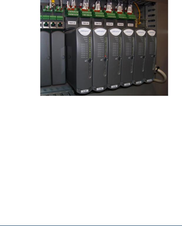
A controller is built from a range of compact plug-in modules that are straightforward to assemble into a system. They can be mounted onto DIN rails in a cabinet (see photograph) or directly mounted onto a wall in a control room. They do not require forced air cooling or special environmental control equipment. However, certain consideration to the cabinet type must be applied when used in hazardous environments.
A secure network communications protocol, developed by Rockwell Automation for the AADvance system, permits distributed control and safety using new or existing network infrastructure while ensuring the security and integrity of the data. Individual sensors and actuators can connect to a local controller, minimizing the lengths of dedicated field cabling. There is no need for a large central equipment room; rather, the complete distributed system can be administered from one or more PC workstations placed at convenient locations.
Single input modules are designed to meet SIL3 and in the most basic simplex configuration they offer a fail-safe solution. The AADvance system has comprehensive built-in diagnostics, while maintenance activities are straight forward operations which maximize system availability.
The AADvance controller is developed and built for IEC 61131 compliance and includes support for all five programming languages. Program access is secured by a removable "Program Enable" key. Simulation software lets you prove a new application before reprogramming and downloading, again maximizing system uptime.
Document: 553630 |
1-5 |
ICSTT-RM446K-EN-P Issue: 10_C |
|

Safety Manual (AADvance Controller)
AADvance Features
The AADvance system controls complex and often critical processes in real time — executing programs that accept external sensor signals, solving logic equations, performing calculations for continuous process control and generating external control signals. These user-defined application programs monitor and control real-world processes in the oil and gas, refining, rail transit, power generation and related industries across a wide range of control and safety applications.
The main features of the AADvance system are as follows:
Facilitates differing fault tolerant topologies — 1oo1, 1oo2D and 2oo3
Flexible modular construction using individual modules to build a system
Operates as a stand alone system or part of a larger distributed network
Easily transformed from a simplex non-safety system to a fault tolerant safety related system
IEC 61508 certified, reviewed and approved by TÜV and UL
Scalable I/O module expansion without system interruption
Supports secure SIL 3 rated 'Black Channel' external communication over Ethernet
Supports industry standard protocols including Modbus and HART
Supports OPC when using an OPC Portal
1-6 |
Document: 553630 |
|
ICSTT-RM446K-EN-P Issue: 10_C |

Associated Documents
The following documents are associated with the safety requirements applicable to the AADvance system. Further supporting information is available on the TÜV web site.
PFH and PFD Data
The PFH and PFD data is provided in a separate document - Doc No: 553847 - PFHavg and PFDavg Data for AADvance Controllers.
Table 2: |
|
Reference Documents |
|
|
|
|
|
|
|
|
Document |
Title |
||
|
|
|
|
|
|
IEC 61508, Part 1-7:1998-2000 |
Functional safety of electrical/electronic programmable |
||
|
|
|
safety-related systems |
|
|
|
|
|
|
|
IEC 61511-1:2004 |
Functional-safety: Safety instrumented systems for the |
||
|
|
|
process industry sector |
|
|
|
|
|
|
|
ANSI ISA 84.00.01:2004 |
Functional Safety: Safety instrumented systems for the |
||
|
(IEC61511-2 Mod) |
process industry sector. |
||
|
|
|
|
|
|
EN 61131-2:2007 |
Programmable controllers – Part 2: Equipment |
||
|
|
|
requirements and tests |
|
|
|
|
|
|
|
NFPA 72:2007 |
National fire alarm and signalling code |
||
|
|
|
|
|
|
NFPA 85:2007 |
Boiler and combustion systems hazard code. |
||
|
|
|
|
|
|
NFPA 86:2007 |
Standards for ovens and furnaces |
||
|
|
|
|
|
|
EN50156-1:2004 |
Electrical equipment for furnaces and ancillary |
||
|
|
|
equipment: Requirements for application design and |
|
|
|
|
installation |
|
|
EN54-2:1997,A1:2006 |
Fire alarm control panels |
||
|
|
|
|
|
|
UL508 |
Industrial control equipment |
||
|
|
|
|
|
|
|
|
|
|
Note: An good understanding of health and safety practices, functional safety principles is highly recommended; and the principles of these standards should be understood before generating procedures and practices to meet the requirements of this Safety Manual.
Document: 553630 |
1-7 |
ICSTT-RM446K-EN-P Issue: 10_C |
|

Safety Manual (AADvance Controller)
Controller TUV Certification
TÜV Certification
TÜV is the safety certifying authority for an AADvance controller, and they have certified The AADvance system to the following standards:
IEC 61508, Part 1- |
EN 50178:1997 |
7:1998-2000 |
|
IEC 61511-1:2004 |
EN 50156-1:2004 |
EN 61131-2:2007 |
EN 54-2:1997, |
|
A1:2006 (†) |
EN 61326-3-1:2008 |
NFPA 72:2007 |
EN 61000-6-2:2005 |
NFPA 85:2007 |
EN 61000-6-4:2007 |
NFPA 86:2007 |
(†) The analogue output modules are not certified to EN 54-2.
You can download a copy of the TUV certificate from www.tuvasi.com.
Certification for use in Hazardous Environments
The AADvance controller has been investigated and approved by UL (UL508) for use as Industrial Control Equipment in a general industrial environment and for use in hazardous locations, Class I, Division 2, Groups A, B, C and D. The UL file numbers are: E341697 and E251761.
File No: E341697
The AADvance controller investigation and approval is contained in the following files:
NRAQ.E341697: Programmable Controllers investigated to ANSI/UL 508.
The products have been investigated using requirements contained in the following standards:
UL508, Industrial Control Equipment, Seventeenth edition, with revisions through and including April 15, 2010.
NRAQ7.E341697: Programmable Controllers Certified for Canada
The products have been investigated using requirements contained in the following standards:
1-8 |
Document: 553630 |
|
ICSTT-RM446K-EN-P Issue: 10_C |

CSA C22.2 No 142-M1987, Process Control equipment, Edition 1 - Revision date 1990-09-01
Products Covered
The products investigated and approved:
Programmable Logic Controllers Models: 9110 Processor Module; 9401/2 Digital Input Module; 9431/2 Analogue Input Module; 9451 Digital Output Module; 9482 Analogue Output Module.
Listed Accessories for use with PLCs: 9100 Processor Backplane, 9300 I/O Backplane, 9801 Digital Input Termination Assembly, Simplex; 9802 Digital Input Termination Assembly, Dual; 9803 Digital Input Termination Assembly, TMR; 9831 Analogue input Termination Assembly, Simplex; 9832, Analogue Input Termination Assembly, Dual; 9833 Analogue Input Termination Assembly, TMR; 9851 Digital Output Termination Assembly, Simplex ; 9852 Digital Output Termination Assembly, Dual; 9881 Analogue Output Termination Assembly, Simplex; 9882 Analogue Output Termination Assembly, Dual.
File No: E251761
The AADvance controller investigation and approval is contained in the following file certifications:
NRAG.E251761: Programmable Controllers for Use in Hazardous Locations Class I, Division 2, Groups A, B, C and D.
The products have been investigated using requirements contained in the following standards:
ANSI/ISA 12.12.01-20007, Nonincendive Electrical Equipment for use in Class I and II, Division 2 and Class III, Division 1 and 2 Hazardous Locations.
UL508, Industrial Control Equipment, Seventeenth edition, with revisions through and including April 15, 2010.
NRAG7.E251761: Programmable Controllers for Use in Hazardous Locations Certified for Canada; Class I, Division 2, Groups A, B, C and D
The products have been investigated using requirements contained in the following standards:
CSA C22.2 No 213-M1987, Nonincendive Control Equipment for Use in Class I, Division 2, Hazardous Locations.
CSA C22.2 No 142-M1987, Process Control equipment, Edition 1 - Revision date 1990-09-01
Products Covered
The products investigated and approved:
Document: 553630 |
1-9 |
ICSTT-RM446K-EN-P Issue: 10_C |
|

Safety Manual (AADvance Controller)
Programmable Logic Controllers Models: 9110 Processor Module; 9401/2 Digital Input Module; 9431/2 Analogue Input Module; 9451 Digital Output Module; 9482 Analogue Output Module.
Listed Accessories for use with PLCs: 9100 Processor Backplane, 9300 I/O Backplane, 9801 Digital Input Termination Assembly, Simplex; 9802 Digital Input Termination Assembly, Dual; 9803 Digital Input Termination Assembly, TMR; 9831 Analogue input Termination Assembly, Simplex; 9832, Analogue Input Termination Assembly, Dual; 9833 Analogue Input Termination Assembly, TMR; 9851 Digital Output Termination Assembly, Simplex ; 9852 Digital Output Termination Assembly, Dual; 9881 Analogue Output Termination Assembly, Simplex; 9882 Analogue Output Termination Assembly, Dual.
1-10 |
Document: 553630 |
|
ICSTT-RM446K-EN-P Issue: 10_C |

Certificate
The AADvance controller modules have been evaluated to the requirements of EN 60079-0: 2009 and EN 60079-15: 2010 under Certificate Number: DEMKO 11 ATEX 1129711X .
Document: 553630 |
1-11 |
ICSTT-RM446K-EN-P Issue: 10_C |
|
Safety Manual (AADvance Controller)
The AADvance controller has also been evaluated under certificate IECEx UL 12.0032X to the standards IEC 60079-0; (5th Edition) and IEC 6007915 (4th Edition).
[ certificate to be supplied]
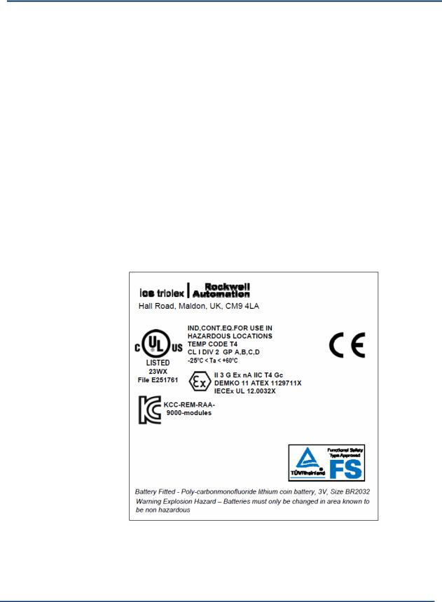
 For a system that is located in a Zone 2 Hazardous environment where ATEX certification is required, all modules should be installed in an ATEX or IECEx Certified, tool accessible IP54 enclosure. The enclosure is to be marked with the following: "Warning - Do not open when energized". After installation of the modules into the enclosure, access to termination compartments shall be dimensioned so that conductors can be readily connected. Modules are for use in an area of not more than pollution degree 2 in accordance with IEC60664-1
Module label
1-12 |
Document: 553630 |
|
ICSTT-RM446K-EN-P Issue: 10_C |

KCC-EMC Registration
Other External Testing and validation
The Euro Controller is also tested to Q1 Extended Design levels of ISO 13628-6: 2006 Sub Sea Production Control System.
Document: 553630 |
1-13 |
ICSTT-RM446K-EN-P Issue: 10_C |
|

Chapter 2
Functional Safety Management
This chapter explains the principles that should be applied to managing the safety related system.
In This Chapter
The Safety Management System...................................................................... |
2-1 |
The Safety Life-cycle .......................................................................................... |
2-2 |
Functional Safety Assessment .......................................................................... |
2-8 |
Safety Integrity Design....................................................................................... |
2-8 |
The Safety Management System
A prerequisite for the achievement of functional safety is the creation and use of procedures and other measures as part of a safety lifecycle, collectively known as a Safety Management System. The Safety Management System defines the generic management and technical activities necessary to achieve and maintain functional safety in the product design and development. In many cases, the Safety Management and Quality systems will be integrated within a single set of procedures. The integrator should have an accredited quality management system.
The Safety Management System shall include:
A statement of the policy and strategy for achieving and maintaining functional safety.
A safety planning procedure, which shall result in the definition of the safety lifecycle stages to be applied, the measures and techniques to be applied at each stage, and the responsibilities for completing these activities.
Definitions of the records to be produced and the methods of managing these records, including change control. The change control procedures shall include records of modification requests, the impact analysis of proposed modifications and the approval of modifications. The baseline for change control shall be defined clearly.
Configuration items shall be uniquely identified and include version information. Examples of configuration items are system and safety requirements, system design documentation and drawings, application software source code, test plans, test procedures and test results.
Methods of ensuring that persons are competent to undertake their activities and fulfill their responsibilities.
Document: 553630 |
2-1 |
ICSTT-RM446K-EN-P Issue: 10_C |
|

Safety Manual (AADvance Controller)
The Safety Life-cycle
The safety life-cycle is defined by the IEC 61508 standard. It is designed to structure a system's development into defined stages and activities as follows:
Scope definition
Hazard and risk analysis
Functional and safety requirements specification
System engineering
Application programming
System production
System integration
System installation and commissioning
Safety system validation
Operation and maintenance plan
System modification
Decommissioning
The definition of each life-cycle stage shall include its inputs, outputs and verification activities. It is not necessary to have separate stages within the lifecycle addressing each of these elements independently; but it is important that all of these stages are covered within the lifecycle. Specific items that need to be considered for each of these life-cycle elements are described in the following sub-paragraphs.
Scope Definition
The scope definition is the first step in the system life-cycle. You have to identify the boundaries of the safety-related system and provide a clear definition of its interfaces with the process and with all third party equipment. This stage should also establish the derived requirements resulting from the intended installation environment, such as environmental conditions and power sources.
In most cases, the client will provide this information. The system integrator must review this information and gain a thorough understanding of the intended application, the bounds of the system to be provided, and its intended operating conditions.
Hazard and Risk Analysis
The hazard and risk analysis has three objectives:
The first objective is to determine the hazards and hazardous events of the controlled system for all reasonably foreseeable circumstances, including fault conditions and misuse.
2-2 |
Document: 553630 |
|
ICSTT-RM446K-EN-P Issue: 10_C |

The second objective is to determine the event sequences that may lead to a hazardous event.
The third objective is to determine the risks associated with the hazardous event.
This risk analysis will provide basic information for identifying the safetyrelated requirements to mitigate risks.
System Functional and Safety Requirements
A set of system functions and their timing requirements will be specified. Where possible, the functions should be allocated to defined modes of operation of the process. For each function, it will be necessary to identify the process interfaces. Similarly, where the function involves data interchange with third party equipment, the data and interface should be clearly identified. Where non-standard field devices, communications interfaces or communications protocols are required, it is especially important that detailed requirements for these interfaces are established and documented at this stage.
The client should provide the functional requirements, where this information is not supplied the System Integrator should define the requirements and agree them with the client. It is, however, necessary to collate these requirements into a document, including any clarification of the requirements. It is recommended that logic diagrams be used to represent the required functionality and highly recommended that all requirements are reviewed, clarified where required and approved by the client.
During the system safety requirements stage the functional requirements are analyzed to determine their safety relevance. Where necessary, additional safety requirements shall be identified and documented to ensure that the plant will fail-safe in the case of failures of the plant, safety-related system, external equipment or communications, or if the safety-related system's environment exceeds the required operating conditions.
The appropriate safety integrity level and safety-related timing requirements shall be defined for each safety-related function. For each function the required safety failure mode shall be determined. The client should supply this information or it should be defined and agreed with the client as part of this phase. The System Integrator shall ensure that the client approves the resulting safety requirements.
System Engineering
The system engineering stage realizes the design of the safety-related system. It is recommended that the engineering be divided into two distinct stages, the first defining the overall system architecture, and the second detailing the engineering of the individual architectural blocks.
Document: 553630 |
2-3 |
ICSTT-RM446K-EN-P Issue: 10_C |
|

Safety Manual (AADvance Controller)
The architectural definition shall define the safety requirements class for each architectural element and identify the safety functions allocated to each element. Additional safety functions resulting from the chosen system architecture shall be defined at this stage.
The detailed engineering design shall refine the architectural elements and culminate in detailed information for system build. The design shall be in a form that is readily understood and allows for inspection and review of each stage of the process and final design.
If the possibility of errors cannot be eliminated, the system integrator should make sure that procedural methods are devised and applied to detect them.
The system design should include facilities to allow field maintenance tasks can be performed.
Each installation shall be designed to ensure that the control equipment is operated in environments that are within its design tolerances. Therefore, the operating environment should provide the proper control of temperature, humidity, vibration and shock, as well as adequate shielding and earthing to minimize that exposure to sources of electromagnetic interference and electrostatic discharge.
2-4 |
Document: 553630 |
|
ICSTT-RM446K-EN-P Issue: 10_C |

Application Programming
Application programs are developed and monitored using the AADvance Workbench software.
An overall application program software architecture shall be defined at the application programming stage. This architecture will identify the software blocks and their functions.
The application programming shall address methods for addressing system specific testing, diagnostics and fault reporting.
It is highly recommended that simulation testing be performed on each software block. The simulation testing should be used to show that each block performs its intended functions and does not perform unintended functions.
It is also highly recommended that software integration testing is performed within the simulation environment before commencing hardware-software integration. The software integration testing should show that all software blocks interact correctly to perform their intended functions and do not perform unintended functions.
The development of the application software shall follow a structured development cycle; the minimum requirements of which are:
Architectural definition. The application program shall be divided into self-contained 'blocks' to simplify the implementation and testing. Safety and non-safety functions should be separated as far as possible at this stage.
Detailed design and coding. The detailed design and coding stage will add detail to the design and implement each of the blocks identified within the architectural definition.
Testing. The testing stage will verify the operation of the application; it is recommended that the application blocks first be tested individually and then integrated and tested as a whole. All of this testing should be initially done within the simulation environment.
Fault handling strategy. This stage defines the fault handling strategy.
The resultant application software shall be integrated with the system hardware and full integration testing performed on the system.
System Production
The system production stage implements the detailed system design. The production techniques, tools and equipment, including those used for production testing of the system, shall be appropriate for the specified safety requirements class.
Document: 553630 |
2-5 |
ICSTT-RM446K-EN-P Issue: 10_C |
|

Safety Manual (AADvance Controller)
System Installation Environment
The installation environment is a potential source of common cause failure, therefore it is vital that compatibility of the equipment with the environment is known. The environment for these purposes includes the prevailing climatic, hazardous area, power, earthing and EMC conditions. In many cases, there will not be a single installation environment. Elements of the system may be installed in differing locations; in these cases, it is important to know the environment for each location.
 You must use installation and commissioning procedures that comply with applicable standards of the country of installation. The applicable standards can include, for example, IEC 61511, NFPA72 and ISA 84.00.01,
depending on the location.
System Integration
The system integration stage shall integrate the application programs with the AADvance controller. Where multiple systems are used to meet an overall requirement, it is recommended that each sub-system undergoes application program and target system integration and testing before commencing overall system integration. To meet the requirements of the intended safety requirements class, the system integration shall result in full compliance of the software and hardware with the functional safety requirements.
System Commissioning
The commissioning stage is to prove the system installation and verify its correct 'end-to-end' functionality, including the connection between the AADvance controller and the requisite sensors and final elements. It is likely that groups of functions are commissioned in stages rather than the system as a whole, for example accommodation area functions before production functions. It is important to define the commissioning sequence and the measures to be taken to ensure safe operation during such periods of partial commissioning. These measures shall be system specific and shall be defined clearly before starting any commissioning. It is also important to define that any temporary measures implemented for test purposes, or to allow partial commissioning, are removed before the system, as a whole, goes live.
Records shall be maintained throughout the commissioning process. These records shall include evidence of the tests completed, any problem reports and the resolution of problems.
2-6 |
Document: 553630 |
|
ICSTT-RM446K-EN-P Issue: 10_C |
 Loading...