


TNC 306

Service Manual
TNC 306/360
10/00
Kundendienst/Service

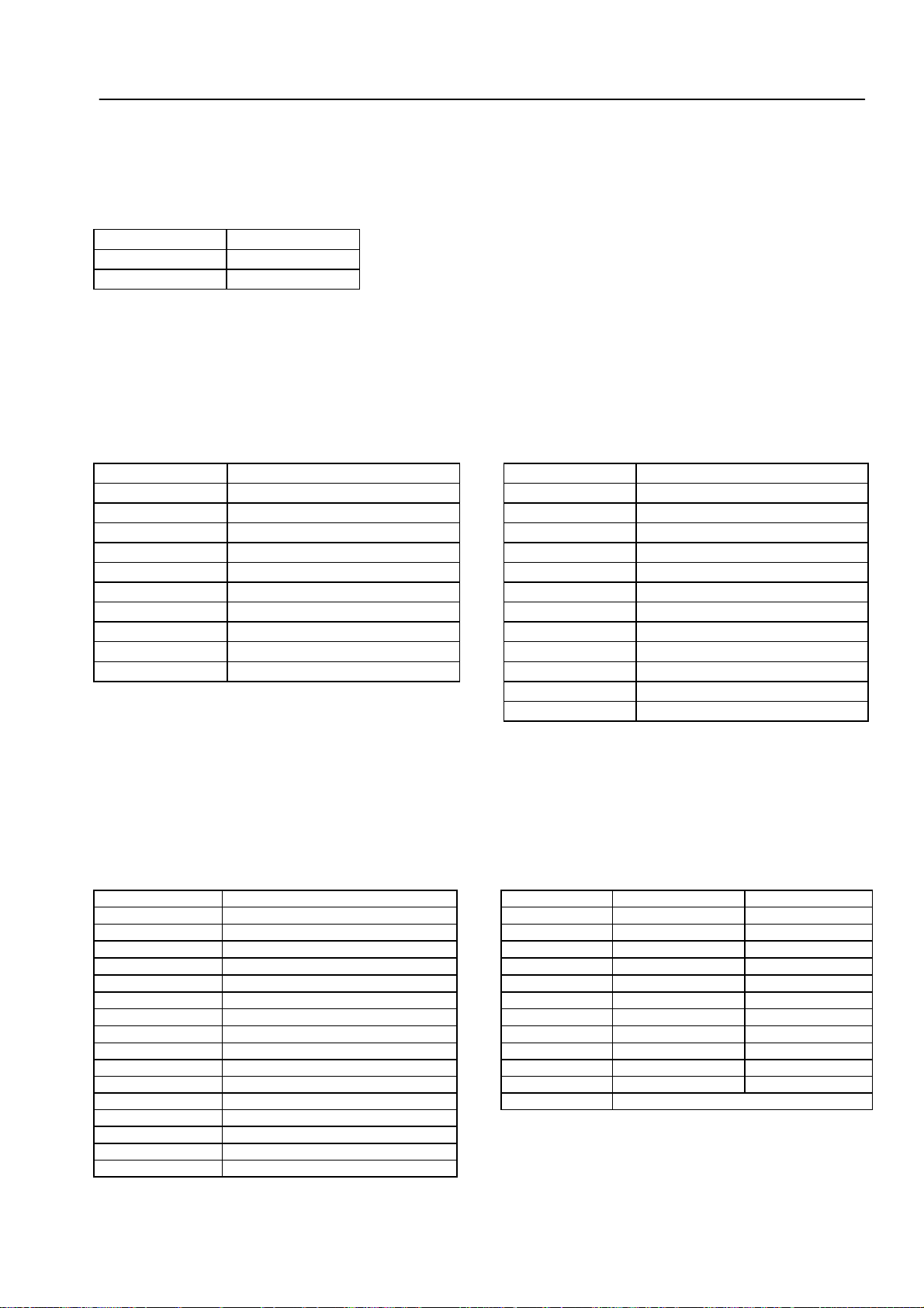
Contents Service Manual TNC 306/360
How to use this Service Manual
Minor Error Messages
Major Error Messages and their Causes
Hardware Components TNC 306/360
Logic Unit LE 360/C
Connector Designation and Pin Layout
Grounding Diagram
Power Supply
Keyboard Unit TE 355 A/B
Visual Display Units for TNC 306/360
Encoders
1
2
3
4
5
6
7
8
9
10
11
Handwheel HR 130/330
3D-Touch Probe Systems
RS-232-C/V.24 Data Interface
External Data Transfer
Analog Outputs
PLC Inputs and Outputs
Test Units
Exchange instructions
Machine Parameters
12
13
14
15
16
17
18
19
20

SERVICE MANUAL TNC 306/360
Page 1
HEIDENHAIN Service
Table of Contents
Page
1. How to use this Service Manual ........................................................3
2. Minor Error Messages...........................................................................4
2.1 Causes of Minor Error Messages................................................................ 5
3. Major Error Messages and their Causes.......................................... 6
4. Hardware Components TNC 306/360.............................................. 12
5. LOGIC UNIT LE 360/C........................................................................... 13
5.1 Designation of the LOGIC UNIT LE 360/C..................................................13
5.2 Hardware Components of the LOGIC UNIT LE 360/C................................ 14
6. Connector Designation and Pin Layout..........................................15
6.1 Connectors on the LOGIC UNIT LE 360/C..................................................15
6.2 Connectors on the PLC I/O Board ..............................................................20
6.3 Connectors on the Keyboard Units TE 355 A/B..........................................23
6.4 Connectors on the Visual Display Units......................................................25
7. Grounding Diagram .............................................................................. 27
8. Power Supply ......................................................................................... 28
8.1 External Power Supply Requirements........................................................ 28
8.2 Power Supply of the Visual Display Units...................................................29
8.3 Power Supply of the NC Part...................................................................... 30
8.4 Checking the Power Supply (Power Supply Unit)....................................... 32
8.5 Power Supply of the PLC ...........................................................................36
8.6 Buffer Battery .............................................................................................38
9. Keyboard Unit TE 355 A/B.................................................................. 39
9.1 Overview ....................................................................................................39
9.2 Checking the Keyboard Unit .......................................................................40
10. Visual Display Units for TNC 306/360 ............................................ 43
10.1 Visual Display Unit BE 212..........................................................................43
10.2 Flat Luminescent Screen BF 110................................................................45
11. Encoders ..................................................................................................46
11.1 Error Messages ..........................................................................................46
11.2 Error Causes ...............................................................................................46
11.3 Checking the Encoders............................................................................... 46
12. Handwheel HR 130/330 ....................................................................... 48
12.1 Overview ....................................................................................................48
12.2 Checking the Handwheel HR 130/330........................................................ 48
12.3 Error Messages ..........................................................................................48

SERVICE MANUAL TNC 306/360
Page 2
HEIDENHAIN Service
Page
13. 3D-Touch Probe Systems.................................................................... 49
13.1 Overview ....................................................................................................49
13.2 Error Messages ..........................................................................................50
14. RS-232-C/V.24 Data Interface............................................................52
14.1 Operating Modes ME - FE - EXT ................................................................52
14.2 Interface Configuration ...............................................................................52
14.3 Connecting Cables and Adaptors for the RS-232-C/V.24 Data Interface ... 54
14.4 Machine Parameters for the RS-232-C/V.24 Interface................................55
14.5 Printer Connection......................................................................................56
14.6 Error Messages ..........................................................................................57
15. External Data Transfer.........................................................................59
15.1 External Data Input .....................................................................................59
15.2 External Data Output ..................................................................................67
16. Analog Outputs...................................................................................... 71
16.1 Specifications .............................................................................................71
16.2 Checking the Analog Outputs.....................................................................71
16.3 Switching Over the Position Display...........................................................73
16.4 Feed Adjustment ........................................................................................73
16.5 Offset Adjustment...................................................................................... 74
17. PLC Inputs and Outputs ...................................................................... 76
17.1 Specifications .............................................................................................76
17.2 Checking the PLC Inputs and Outputs .......................................................77
17.3 Further Diagnosis Possibilities in the PLC Mode........................................81
17.4 Output "Control Ready for Operation" and Acknowledgement
for Test "Control Ready for Operation" .......................................................82
18. TEST UNITS.............................................................................................84
18.1 Test Load Unit ............................................................................................84
18.2 PLC Test Unit .............................................................................................84
18.3 PL Test Unit................................................................................................85
18.4 Measuring Adapter .....................................................................................85
18.5 Encoder Diagnostic Set ..............................................................................87
19. Exchange Instructions ......................................................................... 88
19.1 General Remarks ........................................................................................ 88
19.2 Exchanging the LOGIC UNIT ...................................................................... 92
19.3 Exchanging the PROCESSOR BOARD....................................................... 94
19.4 Exchanging the PLC Board .........................................................................96
19.5 Exchanging the "Power Supply" Assembly ................................................. 98
19.6 Exchanging the PLC I/O Board PL400 ....................................................... 100
19.7 Exchanging EPROMs.................................................................................102
20. Machine Parameters............................................................................103

SERVICE MANUAL TNC 306/360
Page 3
HEIDENHAIN Service
1. How to use this Service Manual
The service manual TNC 306/360 can be used to diagnose, locate and eliminate errors on
machine tools controlled by TNC.
In order to correctly judge the problems in an NC-controlled machine tool, fundamental
knowledge of the machine tool and its drives, as well as their interaction with the control
and the measuring systems is required. Incorrect behaviour of the machine tool can also
result from improper use of the control, NC-programming errors and incorrect or not
properly optimized machine parameters. For further information in this respect please refer
to the .Documentation of the Machine Tool Manufacturer, to the .Operating
Manual (HEIDENHAIN) and to the .Technical Manual (HEIDENHAIN).
The manual for the machine tool manufacturer is not enclosed with every control as is the
operating manual. In general, it is only supplied to the machine tool manufacturer and is
updated by HEIDENHAIN, Traunreut. Therefore, it is absolutely necessary to contact the
machine tool manufacturer if errors occur that are due to a machine parameter or to the
interface of the control. Support will, however, also be provided by the service department
of HEIDENHAIN, Traunreut, and HEIDENHAIN agencies. Telephone numbers, addresses
and telex/telefax numbers can be found on the back side of the cover page and on the back
side of this service manual.
SERVICE MANUAL TNC 306/360
Page 4
HEIDENHAIN Service
2. Minor Error Messages
The TNC 306/360 features a comprehensive integrated monitoring system to avoid input or
operation errors, to locate errors and technical defects of the entire equimpent (TNC,
measuring system, machine tool, cables etc). The monitoring system is a fixed component
of the TNC hardware and software; it is always active when the control is switched on. If a
technical defect or an operation error is detected, an error message in plain language is
displayed on the screen.
CE
To erase minor error messages, press
Further error messages are described in the Operating Manual TNC 306 and TNC
360, in the Technical Manual, in the Documentation by the machine tool
manufacturer or in the Operating Instructions FE 401 B.
.
Error Message
AXIS DOUBLE PROGRAMMED 13.2 ERR: 105 12.6
START POSITION INCORRECT 13.2 ERR: 106 12.6
TOUCH POINT INACCESSIBLE 13.2 ERR: 107 12.6
RANGE EXCEEDED 13.2 ERR: 108 12.6
OPERATING PARAMETER ERASED 2.1 EMERGENCY STOP 17.4
CYCL-PARAMETER INCORRECT 13.2 EXT. IN-/OUTPUT NOT READY 14.6
FAULTY RANGE DATA 13.2 WRONG AXIS PROGRAMMED 13.2
ROTATION NOT PERMITTED 13.2 WRONG PROGRAM DATA 14.6
PLANE WRONGLY DEFINED 13.2 SCALING FACTOR NOT PERMITTED 13.2
ENTRY VALUE INCORRECT 14 PLC: PROGRAM MEMORY ERASED 15.1
LIMIT SWITCH <Axis> 2.1 POSITIONING ERROR <AXIS> 2.1
ERR: 001 12.6 PROGRAM MEMORY EXCEEDED 15.1
ERR: 002 12.6 EXCHANGE BUFFER BATTERY 8.6
ERR: 003 12.6 MIRRORING NOT PERMITTED 13.2
ERR: 004 12.6 RELAY EXT. DC VOLTAGE MISSING 17.4
ERR: 010 12.6 POWER INTERRUPTED 2.1
ERR: 012 12.6 EXCHANGE TOUCH PROBE BATTERY 13.2
ERR: 013 12.6 STYLUS ALREADY IN CONTACT 13.2
ERR: 014 12.6 PROBE SYSTEM NOT READY 13.2
ERR: 100 12.6 TRANSFERRED VALUE ERRONEOUS 14.6
ERR: 102 12.6 TIME LIMIT EXCEEDED 13.2
ERR: 103 12.6
ERR: 104 12.6
Sec.
Error Message
Sec.

SERVICE MANUAL TNC 306/360
Page 5
HEIDENHAIN Service
2.1 Causes of Minor Error Messages
OPERATING PARAMETERS ERASED
- With new and exchange controls, the machine parameters are always erased.
- Software replaced with different version (see section. 15.1)
- Buffer batteries and accumulator defective
- RAM error on PROCESSOR board
LIMIT SWITCH <AXIS>
- "Manual" operating mode:
The pre-determined software limit switch or the additional limit in the auxiliary
operating modes has been reached during traverse with the direction keys.
- "Automatic" operating mode:
The calculated position of the current block is beyond the software limit switch
range or beyond the additional limit. No positioning takes place.
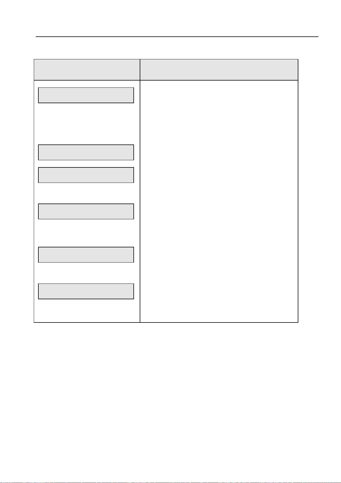
Machine Parameters for Software Limit Switches
X+ X- Y+ Y-
Default setting
Selection via M2816, M2817
Selection via M2816, M2817
Default setting
Selection via M2816, M2817
Selection via M2816, M2817
POWER INTERRUPTED
- After a reset signal at the power supply (e.g. line voltage drops)
- Important machine parameters may have been altered,
e.g. MP 10, MP 210, MP 1390, MP 4010, MP 7210 etc.
- For further causes see section 15.1 and 17.4
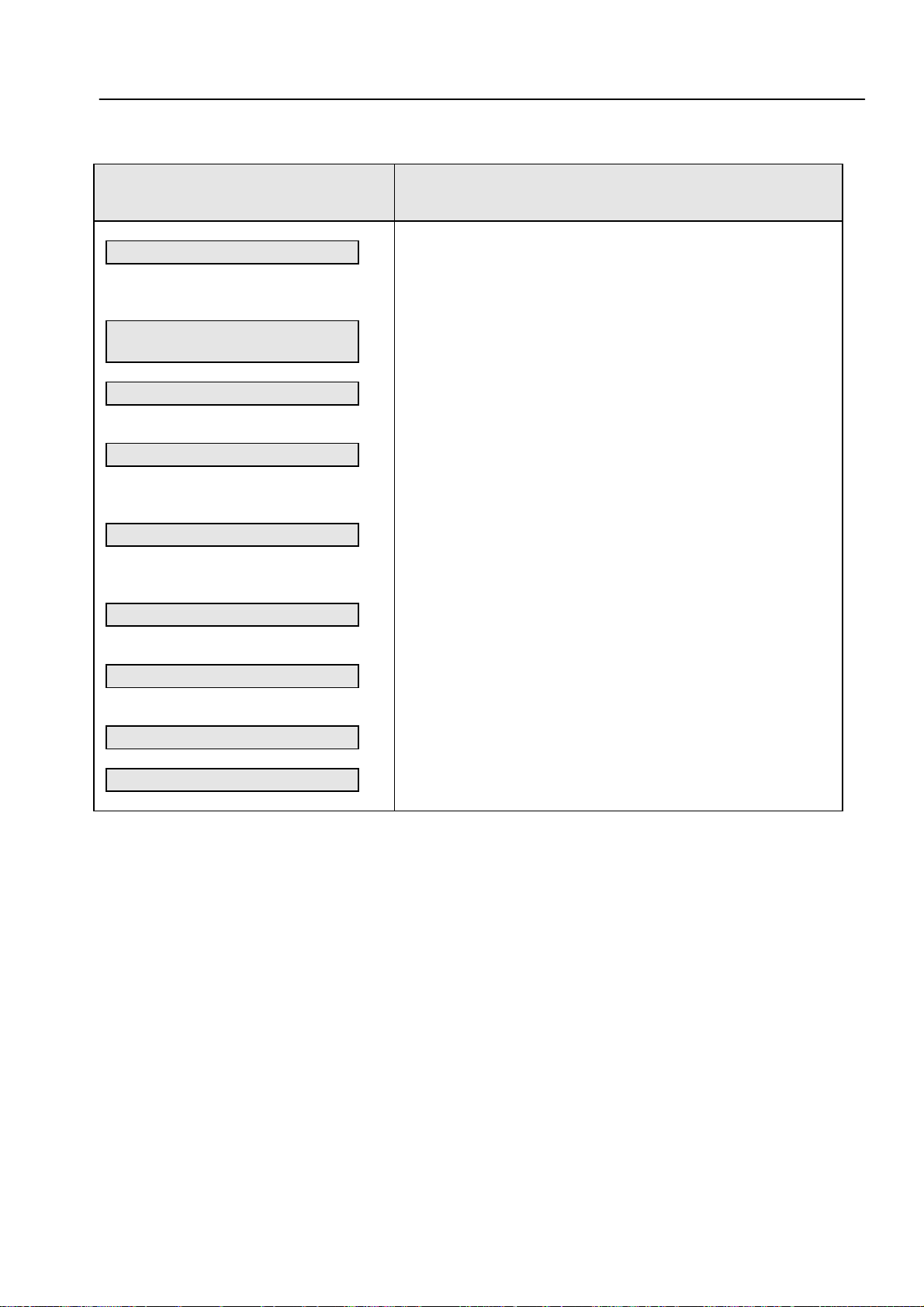
POSITIONING ERROR <AXIS>
910.0
911.0
912.0
Z+ Z- IV+ IV-
910.2
911.2
912.2
920.0
921.0
922.0
920.2
921.2
922.2
910.1
911.1
912.1
910.3
911.3
912.3
920.1
921.1
922.1
920.3
921.3
922.3
- The position monitoring system set in the machine parameters 1410 or 1710 has
responded. (Check the approach behaviour of the axis and readjust, if necessary.)
EMERGENCY STOP
-The EMERGENCY STOP loop has been interrupted (see section 17.4).
-The PLC editor program has been translated
SERVICE MANUAL TNC 306/360
Page 6
HEIDENHAIN Service
3. Major Error Messages and their Causes
The integrated monitoring system distinguishes between minor and major errors; major
error messages (e.g. malfunctions of the encoders, of the drives or data processing errors)
blink. In the case of gross errors, the control opens the contact "Control Ready for
Operation" which causes an emergency stop of the machine tool.
END
By switching off the main switch or pressing
reset, provided that the error cause has been eliminated.
Screen Display (blinking error message) Error Cause
, the "emergency stop" state can be
PROCESSOR CHECK ERROR XX
XX = 08
0C
10
14
18
20
24
28
2C
30
34
38
3C
40
44
48
4C
50
54
58
5C
60
64-7C
94-BC
Bus error
Address errror
Illegal instruction
Division by 0
Error output for CHK command
(check range)
Error output for TRAPV command
(trap on overflow)
Privilege infringement (supervisor
command in the user-mode)
Emulator trap
Emulator trap
-
-
Interrupt vector not initialized
Interrupt vector not initialized
Interrupt vector not initialized
Interrupt vector not initialized
-
-
-
-
False interrupt (interrupt with priority
0)
Interrupt autovector 4-7, user
Interrupt. $100-$3FC
-
If the error message "PROCESSOR CHECK ERROR XX" (XX = identification letters,
see above) comes up repeatedly, please return the complete logic unit to HEIDENHAIN
for repair. Indicate also the error message and the identification letters.
Notes

SERVICE MANUAL TNC 306/360
Page 7
HEIDENHAIN Service
Screen Display (blinking error message) Error Cause
PROCESSOR CHECK ERROR X
X = 0
CRC sum control data incorrect
1
CRC sum machine parameter incorrect
2
Check sum of NC memory incorrect
3
Test plane incomplete
4
Crosstalk between data bits in the RAM
5
Crosstalk between addresses in the RAM
6
Stack overflow
7
CRC sum PLC program ASCII
8
CRC sum PLC program Opcode
A
Software error main processor
B
Software error display task
C
Time slice overflow
D
Command stack overflow control loop
E
Wrong command MAIN PROCESSOR
TASK → CONTROL LOOP TASK
F
Wrong display mode MAIN PROCESSIR
TASK → DISPLAY TASK
H
Control loop: "counter not latched"
L
Wrong control loop command
M
Operating voltage out of tolerance
P
Disabled software function is activated
R
PLC Positioning, datum shift (PLC), spindle
orientation or limit switch
shift active with MP7440 bit 2 = 1 or
MP3030 = 1
If the error message "PROCESSOR CHECK ERROR XX" (X= identification letter, see
above!) comes up repeatedly, please return the complete logic unit to HEIDENHAIN for
repair. Indicate also the error message and the identification letters.
Notes

SERVICE MANUAL TNC 306/360
Page 8
HEIDENHAIN Service
Screen Display (blinking error message) Error Cause
ERROR IN PLC PROGRAM XX
XX = 1A
1B
1C
1D
1E
1F
1G
1H
1I
1J
1K
1L
1M
1N
1O
1P
1Q
XX = 2A
2B
2C
2D
2E
2F
2G
2H
2K
2L
2O
NC start
Rapid traverse
Ref. pulse latch
Feed enable
PLC-Pos X
PLC-Pos Y
PLC-Pos Z
PLC-Pos IV
1)
1)
1)
1)
X+
XY+
YZ+
ZIV+
IVMarker M2485
Marker M2486
Marker M2487
2 of 3 set
SM X+
SM XSM Y+
SM YSM Z+
SM ZSM IV+
SM IV(reserved)
(reserved)
(reserved)
complement missing
complement missing
complement missing
complement missing
complement missing
complement missing
complement missing
complement missing
complement missing
complement missing
complement missing
complement missing
complement missing
complement missing
complement missing
(M03)
(M04)
(M05)
complement missing
complement missing
complement missing
complement missing
complement missing
complement missing
complement missing
Note
50
Excessive nesting of subroutines
51
Stack underflow
52
Stack overflow
53
Time out PLC
54
CASE arguments are larger than the table
values
1) Only active with compatibility mode TNC 355

SERVICE MANUAL TNC 306/360
Page 8.1
HEIDENHAIN Service
Display (blinking) Error Cause
ERROR IN PLC-PROGRAM X X = 7 Called label has not been defined.
89No end-program conditin found (the
program does not contain an EM instruction
or it contains a JP instruction without a
following LBL instruction)
Program is too long (RAM overflow)
(insufficient memory for the program code
which is to be generated)
ERROR IN PLC-PROGRAM
XX
XX = 10 Assign with parenthesis (an =, S, SN, RN, or
PS instruction has been programmed,
although arithmetic parentheses are open)
11
Excessive nesting of parentheses (more
than 16 parentheses are open)
12
Jump within a gating sequence
(unconditional jump has been programmed,
although the gating sequence was not
closed with an Assign)
13
"Close Parentheses" without "Open
Parentheses" (a "Close Parentheses"
command was programmed although no
parentheses were open)
14
Label within parentheses (a LBL instruction
has been programmed, although
parentheses are open)
15
Label within a gating sequence (a LBL
instruction has been programmed, although
the previous gating was not closed with an
Assign)
16
Jump within parentheses (a jump
instruction has been programmed, although
parentheses are open)
17
Parentheses are open at end of block (an
EM instruction has been programmed,
although parentheses are open)
18
Label defined twice
19
Word Assign missing (a Logic instruction
has been programmed. although the
previous Word-gating was not closed with
an Assign)
20
Logic Assign missing (a Word instruction
has been programmed, although the
previous Logic-gating was not closed with
an Assign)
21
Word accumulator not loaded (a Word
Assign or gating has been programmed,
although the Logic accumulator does not
contain a definite value)
22
Logic accumulator not loaded (a Logic
Assign has been programmed, although the
Logic accumulator does not contain a
definite value)

SERVICE MANUAL TNC 306/360
Page 8.2
HEIDENHAIN Service
Display (blinking) Error Cause
ERROR IN PLC-PROGRAM XX XX = 23 Accumulators not loaded on "Open Paren-
(continued)
theses" (an A[, AN[, O[, ON[ or XON[
command has been programmed, although
neither the Word nor the Logic accumulator
has been gated or loaded)
24
Incorrect type of the parentheses result (a
different type has been calculated in the
parentheses from that which was defined at
the "Open Parentheses" command, i.e.
Logic instead of Word or vice versa)
25
Conditional jump with incorrect Logic
accumulator (a conditional jump has been
programmed, although the Logic
accumulator does not contain a definite
value)
26
Empty CASE-instruction
27
"END-CASE" missing
Notes
HEIDENHAIN Service
SERVICE MANUAL TNC 306/360
Page 9
Screen Display
(blinking error message)
GROSS POSITIONING ERROR
<AXIS> A
GROSS POSITIOINING ERROR
<AXIS> B
GROSS POSITIONING ERROR
<AXIS> C
GROSS POSITIONING ERROR
<AXIS> D
GROSS POSITIONING ERROR
<AXIS> E
Error Cause
Position Monitoring (Servo Lag)
- Operation with feed pre-control:
position monitoring range exceeded (range defined
in machine parameter 1420)
- Operation with servo lag:
servo lag monitoring range exceeded (defined in
machine parameter 1720)
Monitoring of the Analog Voltage Limit
- The nominal voltage calculated by the control has
reached its limit of ± 10 V (only with feed precontrol).
Movement Monitoring
- The voltage difference calculated by the control has
reached the limit programmed in the machine parameter 1140.
Standstill Monitoring
- The deviation from the nominal position of an axis in
standstill has exceeded the value programmed in
machine parameter 1110.
- The nominal position was moved beyond during
positioning (overshooting).
Monitoring of Offset Voltage
- The offset voltage of 100 mV has been reached during
an automatic offset adjustment with machine parameter
1220. (see section 16.5)
GROSS POSITIONING ERROR
<AXIS> F
Central Drive Monitoring
- An error in the configuration of the central drive has been
detected (e.g. two analog outputs are active
simultaneously).
Possible location of the error, when the error message
"GROSS POSITIONING ERROR <AXIS> A/B/C/D/E/F" is generated:
When this error message is generated, the error may be located in any element of the
closed loop.
e.g. - Control error (e.g. CLP board)
- Excessive offset voltage at the servo amplifier
- Monitoring function of the servo amplifier has responded
(e.g. power monitoring)
- Servo amplifier defective
- Motor, tachometer, encoder or cables defective
- Mechanical defect (bearings, spindle, guides)
- Excessive mechanical forces on a drive

SERVICE MANUAL TNC 306/360
Page 10
HEIDENHAIN Service
Screen Display (blinking error message) Error Cause
MEASURING SYSTEM <AXIS>
DEFECTIVE A
MEASURING SYSTEM <AXIS>
DEFECTIVE B
MEASURING SYSTEM <AXIS>
DEFECTIVE C
Notes
A = Signal amplitude error
B = Signal frequency error
C =Error with distance-coded scales
Possible Reasons:
- Encoder not connected
- Cable damaged
- Glass scale contaminated or damaged
- Scanning head defective
- Encoder monitoring system defective
(CLP board)
Encoder check: see section 11.3
HEIDENHAIN Service
SERVICE MANUAL TNC 306/360
Page 11
Screen Display
(blinking error message)
WRONG REFERENCE POINT
TNC-OPERATING TEMPERATURE
EXCEEDED
EMERGENCY STOP DEFECTIVE
EMERGENCY STOP PLC
PLC: ERROR 00
PLC: ERROR 99
1)
to
1)
Error Cause
Wrong reference mark spacing entered with distance-coded
linear encoders (counting error caused by the encoder or the
LOGIC UNIT)
The temperature inside the LOGIC UNIT has exceeded
+ 70°C.
Error during the test routine for the output "Control Ready
for Operation" when the machine is switched on (see
section 17.4)
This error message is only generated, if one of the markers
(M2924 - M3023) is set.
Marker 2924
to and marker 2815 set
Marker 3023
CHECK SUM ERROR 1A
CHECK SUM ERROR 1B
CHECK SUM ERROR 1C
2)
2)
2)
Wrong CRC sum NC EPROMs 1/2
Wrong CRC sum PLC-EPROM
Wrong CRC sum NC EPROMs 3/4
CRC = Cyclic Redundancy Check (during data transfer)
1)
With customized PLC programs, a different dialog may be displayed instead of
"PLC: ERROR 00 ...99". For further information, please contact your machine tool
manufacturer.
2)
If the error message "CHECK SUM ERROR YX" comes up repeatedly, please
return the complete logic unit to HEIDENHAIN for repair. Indicate also the
check sum error.
Notes
SERVICE MANUAL TNC 306/360
Page 12
HEIDENHAIN Service
4. Hardware Components TNC 306/360
TNC 306
1)
TNC 360
2)
TNC
Component TNC 306 E TNC 306 C TNC 360 TNC 360 C
LOGIC UNIT LE 360
Id.No. 258 991 -- x
Id.No. 264 660 -- x
Id.No. 264 085 -- x x
LOGIC UNIT LE 360 C
Id.No. 270 641 -- x
Id.No. 270 642 -- x x
VISUAL DISPLAY UNIT BE 212
Id.No. 242 370 -- x x
FLAT SCREEN BF 110
Id.No. 267 209 -- x x
KEYBOARD TE 355 A/B
Id.No. 255 015 -- x x x x
Id.No. 255 016 -- x x x x
PLC I/O BOARD PL 400 (Optional)
Id.No. 255 855 -- x x x x
1) EDM control
2) Milling control
SERVICE MANUAL TNC 306/360
Page 13
HEIDENHAIN Service
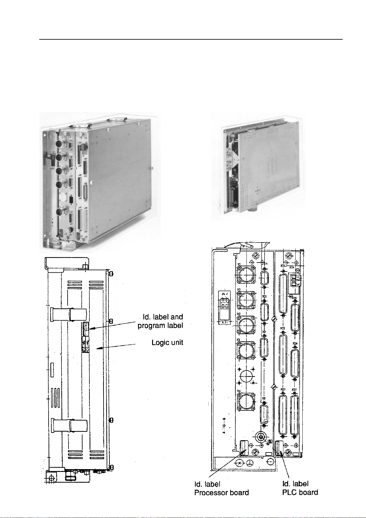
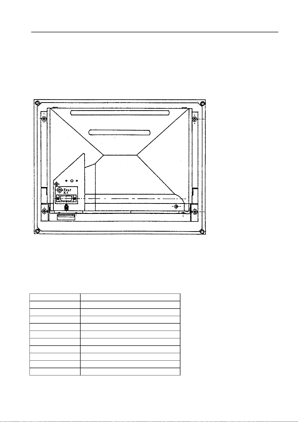
5. LOGIC UNIT LE 360/C
5.1 Designation of the LOGIC UNIT LE 360/C
Logic Unit LE 360/C without
PLC I/O Board (PL 400)
The PLC I/O Board PL 400 is preferrably
mounted to the top of the LE.
SERVICE MANUAL TNC 306/360
Page 14
HEIDENHAIN Service
5.2 Hardware Components of the LOGIC UNIT LE 360/C
The LOGIC UNIT consists of the following components:
- Power supply
- Processsor board
- PLC board
- PLC I/O board PL 400 (optional)
5.2.1 Overview of Boards and Components
LE LE 360 LE 360 C
258 991 -- 264 660 -- 264 085 -- 270 641 -- 270 642 1- 270 642 2-
PROCESSOR BOARD
Id.No. 259 765 -- x
Id.No. 263 728 -- x
Id.No. 265 220 -- x
Id.No. 268 559 -- x
Id.No. 270 637 -- x x
PLC BOARD
Id.No. 259 850 -- x x
Id.No. 263 421 -- xxxx
POWER SUPPLY
Id.No. 236 484 -- xxxxxx
PLC I/O BOARD (optional)
Id.No. 255 855 -- xxxxxx
SERVICE MANUAL TNC 306/360
Page 15
HEIDENHAIN Service
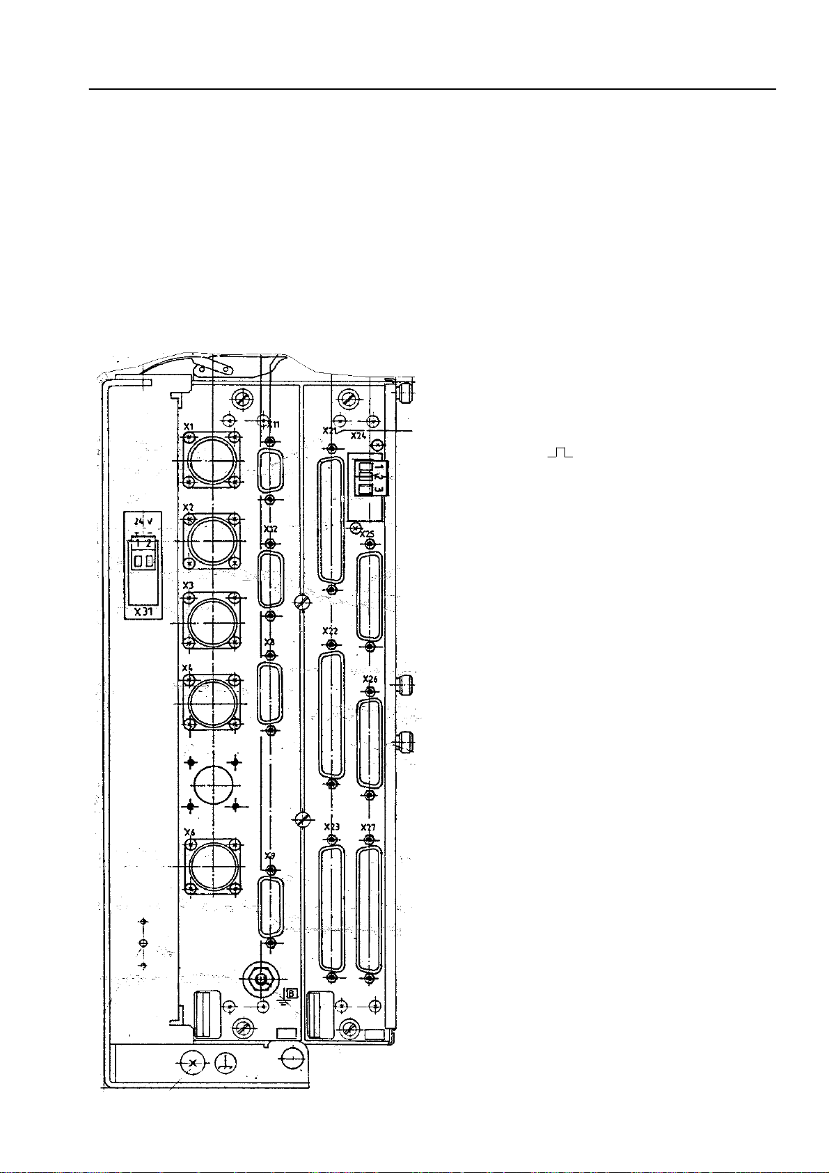
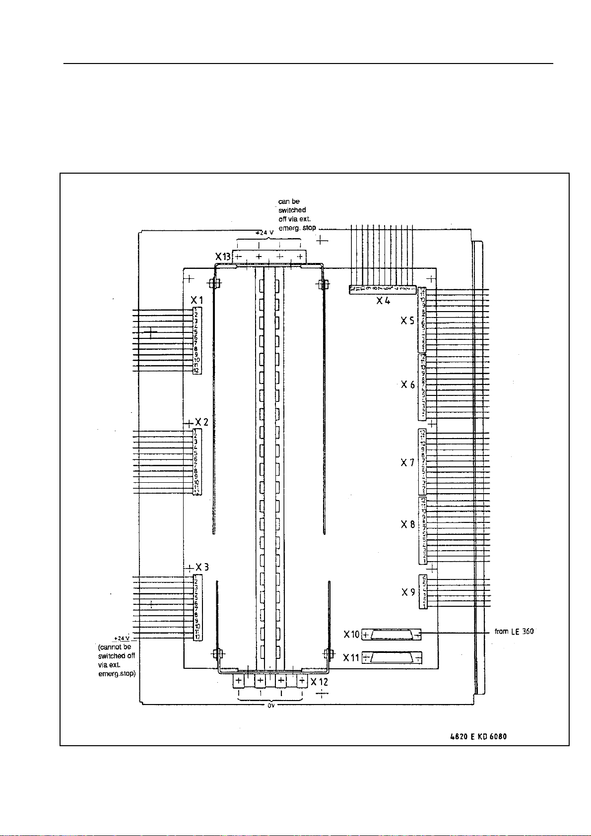
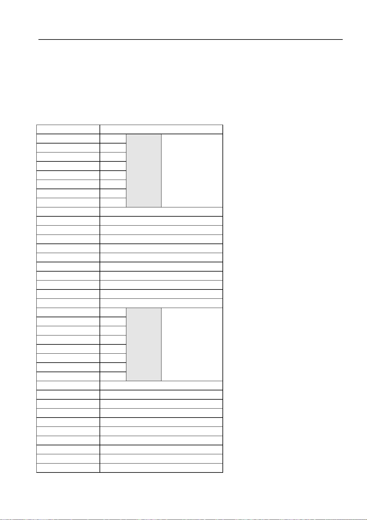
6. Connector Designation and Pin Layout
6.1 Connectors on the LOGIC UNIT LE 360/C
6.1.1 Connector Designation: LOGIC UNIT LE 360/C
Power Processor- PLC
supply board board
Processor board
X1 = encoder 1 (∼)
X2 = encoder 2 (∼)
X3 = encoder 3 (∼)
X4 = encoder 4 (∼)
X6 = encoder S (
X8 = nominal value output 1, 2, 3, 4, S
X9 = VDU (BE or BF)
X11 = handwheel HR 130/330
X12 = touch probe system
)
B = signal ground
PLC board
X21 = PLC output
X22 = PLC input
X23 = TNC operating panel (TE)
X24 = power supply 24 V for PLC
X25 = data interface V.24/RS-232-C
X26 = PLC I/O board (PL 400)
X27 = machine operating panel (MB)
Power supply
X31 = power supply 24 V for LE
SERVICE MANUAL TNC 306/360
Page 16
HEIDENHAIN Service
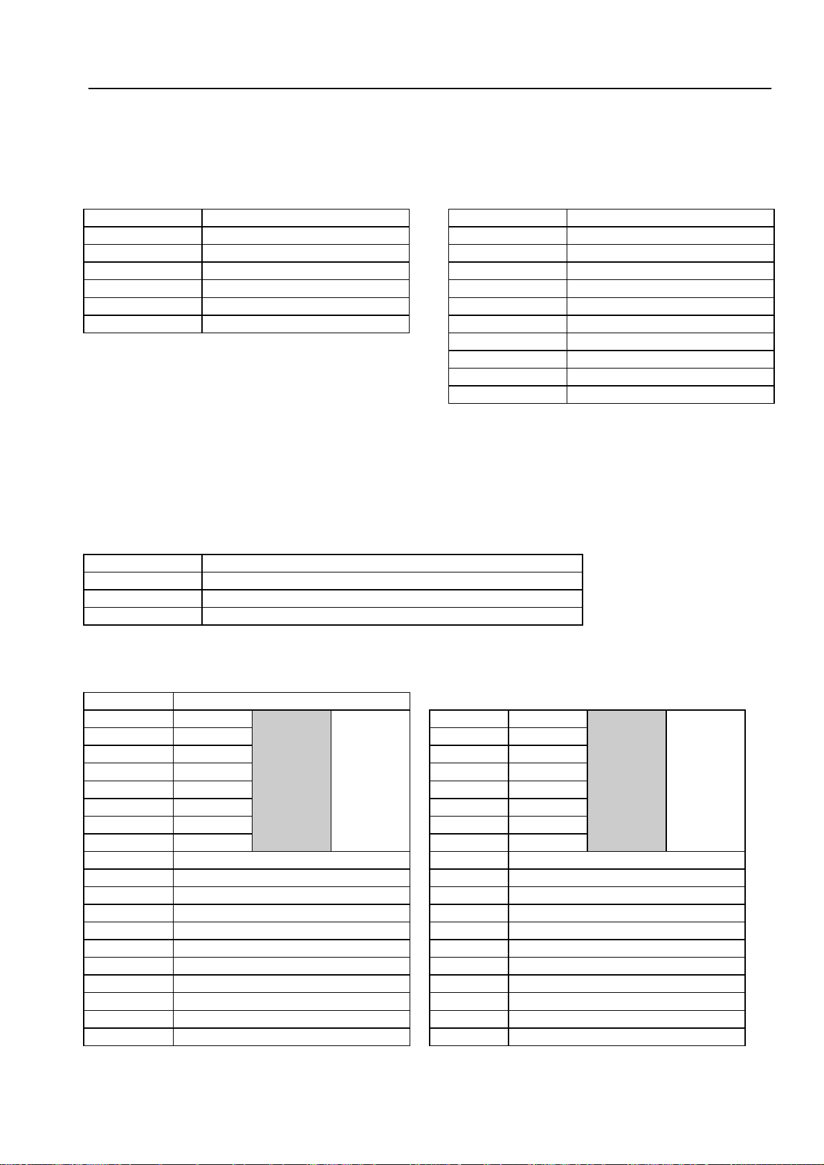
6.1.2 Pin Layout: POWER SUPPLY
X31 Power supply (NC)
Terminal block (pluggable) 2-pin
Pin No. Assignment
1 + 24 V
20V
6.1.3 Pin Layout : PROCESSOR BOARD
X1, X2, X3, X4,
X6 Encoder S
Encoder 1, 2, 3, 4
Sine-wave input
Flange socket with female insert (9-pin)
Square-wave input
Flange socket with female insert (12-pin)
Pin No. Assignment Pin No. Signal
1 0°+ 5 Ua1
2 0°- 6 -Ua1
5 90°+ 8 Ua2
6 90°- 1 -Ua2
7 RI+ 3 Ua0
8 RI- 4 -Ua0
3 + 5 (Up) 7 UaS
4 0 V (Un) 2 + 5V (sensor line)
9 internal shield 12 + 5V (Up)
Housing external shield = housing 11 0 V (sensor line)
10 0 V (Un)
9 (via spring) shield = housing
X8 Nominal Value Output
X9 Visual Display Unit
1,2,3,4,S (TNC 360)
1,2,3,4 (TNC 306)
Flange socket with female insert (15-pin) Flange socket with female insert (15-pin);
interface adjustment for BE 212 or
BF 110 via jumper
Pin No. Signal Pin No. BE 212 BF 110
1
2 analog input (0 ... 4.999 V) max. 2, 4 + 12 V supply 3
4
5
6 0V analog output 5. axis 10 H SYNC 7
8
9 0V analog output 1. axis 13 video
10 0V analog input 14 - H SYNC 2
11 0V analog input 2. axis 15 - CLOCK
13 0V analog input 3. axis Housing external shield = housing
14 0V analog input 4. axis
15 0V analog input S. axis
12 not assigned
Housing external shield = housing
10V analog output 1. axis
±
10V analog output 2. axis
±
10V analog output 5. axis
±
10V analog output 3. axis
±
10V analog output 4. axis
±
10V analog output S-axis
±
1, 8 0 V supply -
3, 5, 6 do not assign do not assign
7 - Video
9 V SYNC V SYNC
11 - 0 V signal
12 0 V signal -
1)
only with C versions
1)
SERVICE MANUAL TNC 306/360
Page 17
HEIDENHAIN Service
X11 Electronic Handwheel HR 130/HR 330 X12 Touch Probe System TS 120 (TS
111/TS 511, only via adaptor cable
Flange socket with female insert (9-pin) Flange socket with female insert (15-pin)
Pin No. Signal Designation Pin No. Signal Designation
1,3,5,7,9 do not assign 1 internal shield
2 GND (0V) 3 ready for operation
4 + 12 V 4 start
6 DTR 5 + 15 V
8 RxD 6 + 5V (Up)
Housing external shield 7 -battery warning
8 0 V (Un)
9 trigger signal
10 -trigger signal
2, 11 to 15 not assigned
1)
Stylus at rest = high level
1)
6.1.4 Pin Layout: PLC Board
X44 Power Supply (PLC part)
Terminal block (pluggable) 3-pin
Pin No. Assignment
1 + 24 V_A can be switched off with EMERCENCY STOP
2 + 24 V cannot be switched off with EMERGENCY STOP
30 V
X23 TNC Operating Panel (TE)
Flange socket with female insert (37-pin)
Pin No. Assignment
1 RL0 20 SL0
2 RL1 21 SL1
3 RL2 22 SL2
4 RL3 for key 23 SL3 for key
5 RL4 matrix 24 SL4 matrix
6 RL5 25 SL5
7 RL6 26 SL6
8 RL7 27 SL7
9 do not assign 28 do not assign
10 do not assign 29 do not assign
11 do not assign 30 do not assign (internally on 0 V)
12 do not assign 31 do not assign
13 do not assign 32 do not assign
14 do not assign 33 do not assign
15 do not assign 34 spindel override (wiper)
16 do not assign 35 feed override (wiper)
17 do not assign 36 + 5 V override potentiometer
18 do not assign 37 0 V override potentiometer
19 do not assign housing external shield
SERVICE MANUAL TNC 306/360
Page 18
HEIDENHAIN Service
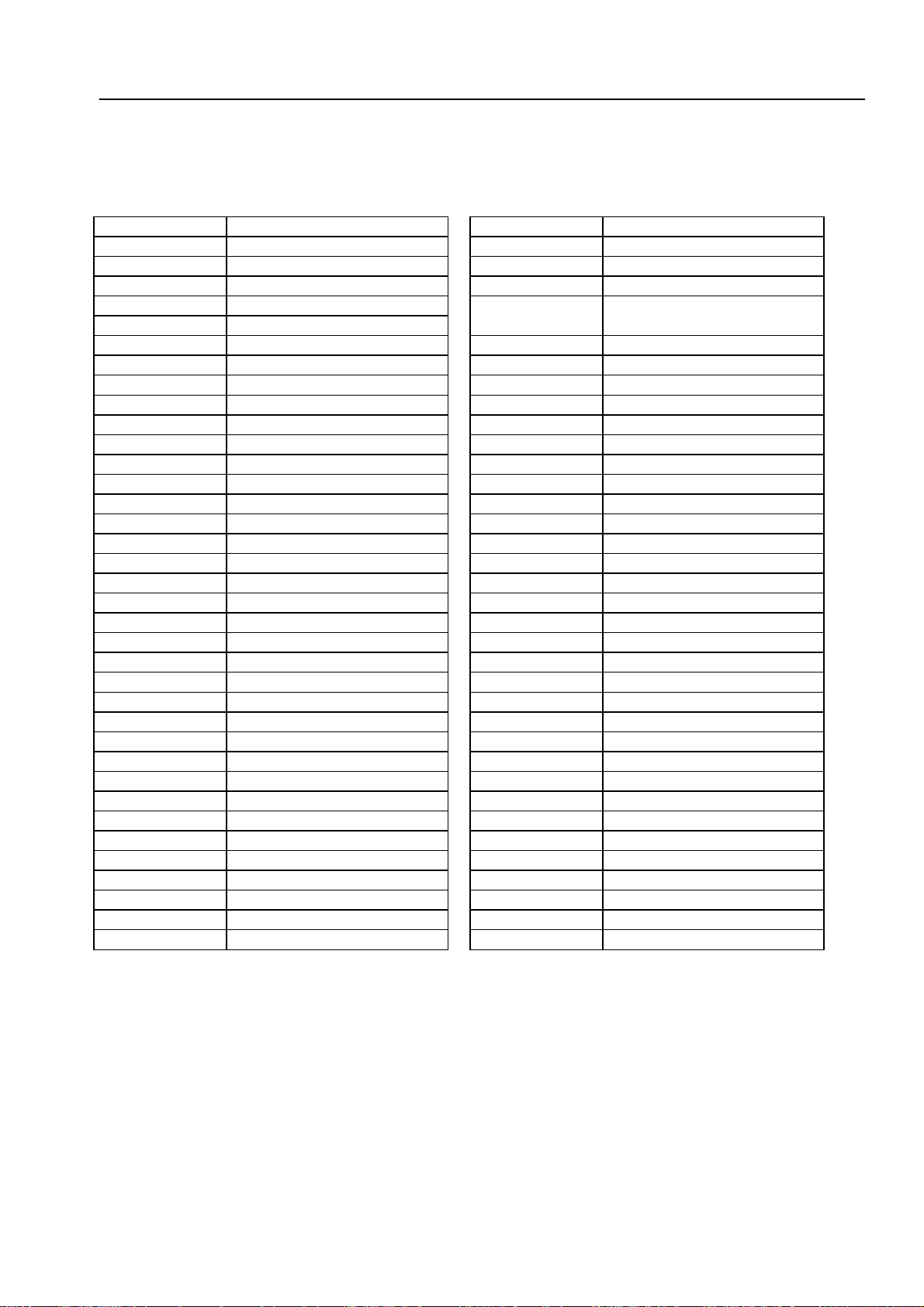
X21: PLC Output X22: PLC Input
Flange socket with female insert (37-pin) Flange socket with female insert (37-pin)
Pin No. Assignment Pin No. Assignment
1O0 1I0
2O1 2I1
3O2 3I2
4 O3 4 I3 acknowledgement for test
5 O4 "Control Ready for Operation"
6O5 5I4
7O6 6I5
8O7 7I6
9O8 8I7
10 O7 9 I8
11 O10 10 I9
12 O11 11 I10
13 O12 12 I11
14 O13 13 I12
15 O14 14 I13
16 O15 15 I14
17 O16 16 I15
18 O17 17 I16
19 O18 18 I17
20 O19 19 I18
21 O20 20 I19
22 O21 21 I20
23 O22 22 I21
24 O23 23 I22
25 O24
26 O25
27 O26
28 O27
29 O28
30 O29
31 O30
32 do not assign 31 I30
33 0 V (PLC)
34 control ready for operation
35,36,37 + 24 V_A PLC
housing external shield housing external shield
2)
2)
2)
2)
2)
2)
2)
1)
3)
2)
24 I23
25 I24
26 I25
27 I26
28 I27
29 I30
30 I29
32 I31
33,34 do not assign
35,36,37 0V PLC
1)
1)
0 V PLC reference potential for testing
2)
Cannot be switched off with EMERGENCY STOP
3)
+ 24 V_A power supply for PLC testing (can be switched off)
SERVICE MANUAL TNC 306/360
Page 19
HEIDENHAIN Service
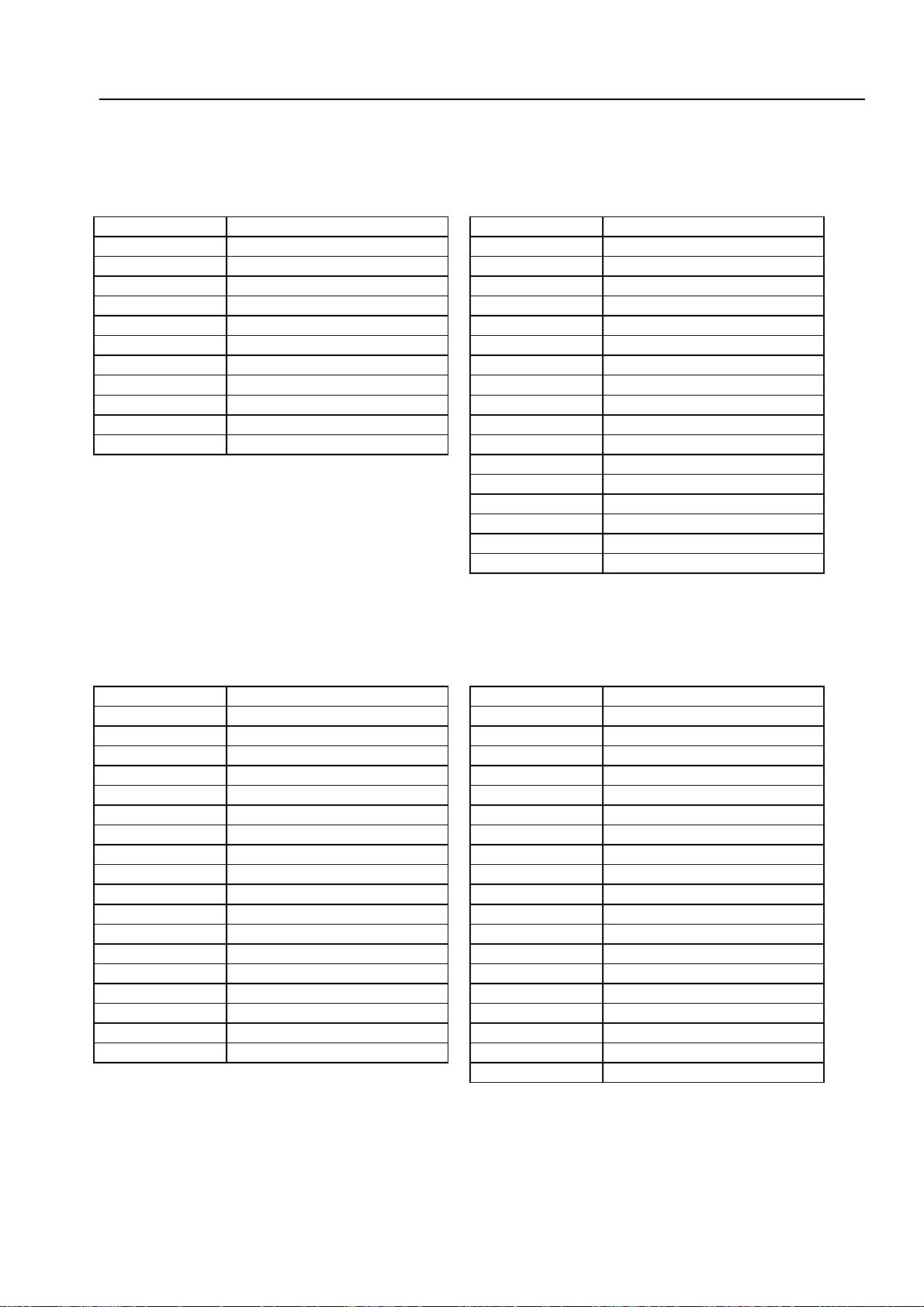
X25 Data Interface V.24/RS-232 X26 PLCI/O Board (PL)
Flange socket with female insert (25-pin) Flange socket with male insert (25-pin)
Pin No. Assignment Pin No. Assignment
1 shield 1, 2, 3 0 V * 1
2 RxD 4, 5, 6, 17, 18 not assigned
3 TxD 7 -RESET
4 CTS 8 -WRITE EXTERN
5 RTS 9 WRITE EXTERN
6 DTR 10 -A5
7 GND (0 V * 2) 11 -A3
8 bis 19 not assigned 12 -A1
20 DSR 13 shield
21 bis 25 not assigned 14, 15, 16 + 12 V * 1
housing external shield 19 serial IN 1
20 EMERGENCY STOP
21 -serial OUT
22 serial OUT
23 -A4
24 -A2
25 -A0
X27 Machine Operating Panel
Flange socket with female insert (37-pin)
Pin No. Assignment Pin No. Assignment
1 I128 19 I146
2 I129 20 I147
3 I130 21 I148
4 I131 22 I149
5 I132 23 I150
6 I133 24 I151
7 I134 25 do not assign
8 I135 26 O0
9 I136 27 O1
10 I137 28 O2
11 I138 29 O3
12 I139 30 O4
13 I140 31 O5
14 I141 32 O6
15 I142 33 O7
16 I143 34 0 V (PLC)
17 I144 35 0 V (PLC)
18 I145 36 + 24 V_A PLC
1)
2)
3)
37 + 24 V_A PLC
O0...O7 simultaneously to X21 (PLC output)
0V PLC reference potential for testing
PLC voltage supply + 24V_A routed via fuse for
the inputs (can be switched off)
1)
1)
1)
1)
1)
1)
1)
1)
2)
2)
3)
3)
SERVICE MANUAL TNC 306/360
Page 20
HEIDENHAIN Service
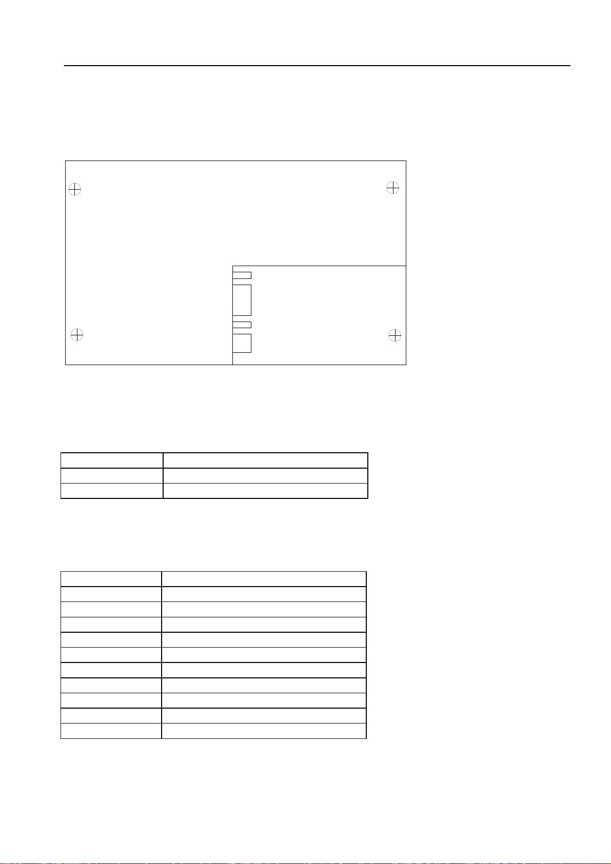
6.2 Connectors on the PLC I/O Board
6.2.1 Connector Designation: PLC I/O Board PL 400
SERVICE MANUAL TNC 306/360
Page 21
HEIDENHAIN Service
6.2.2 Pin Layout: PLC I/O Board PL 400
X1
Pin No.
X2
Pin No.
Assignment
PL 400
1 O32 1 I126
2 O33 2 I74
3 O34 3 I73
4 O35 4 I72
5 O36 5 I71
6 O37 6 I70
7 O38 7 I69
8 O39 8 I68
9 O40 9 I67
10 O41 10 I66
11 O42 11 I65
12 do not assign 12 I64
Assignment
PL 400
1 O43 1 I86
2 O44 2 I85
3 O45 3 I84
4 O46 4 I83
5 O47 5 I82
6 O48 6 I81
7 O49 7 I80
8 O50 8 I79
9 O51 9 I78
10 O52 10 I77
11 O53 11 I76
12 do not assign 12 I75
X4
Pin No.
X5
Pin No.
Assignment
PL 400
Assignment
PL 400
X3
Pin No.
1 O54 1 I98
2 O55 2 I97
3 O56 3 I96
4 O57 4 I95
5 O58 5 I94
6 O59 6 I93
7 O60 7 I93
8 O61 8 I91
9 O62 9 I90
10 control ready for operation 10 I89
11 do not assign 11 I88
12 + 24 V cannot be switched 12 I87
1)
+ 24 V must always be connected, even if the outputs are not used.
Assignment
PL 400
off via EMERGENCY STOP
X6
Pin No.
Assignment
PL 400
SERVICE MANUAL TNC 306/360
Page 22
HEIDENHAIN Service
X7 Assignment X10 Connection to LE
Pin No. PL 400 Pin No. Assignment
1 I110 1,2,3 0 V
2 I109 4 serial IN 2
3 I108 5,6,17,18 not assigned
4 I107 7 -RESET
5 I106 8 -WRITE EXTERN
6 I105 9 WRITE EXTERN
7 I104 10 -A5
8 I103 11 -A3
9 I102 12 -A1
10 I101 13 shield
11 I100 14,15,16 + 12 V
12 I99 19 serial IN 1
20 EMERGENCY STOP
21 -SERIAL OUT
X8 Assignment 22 SERIAL OUT
Pin No. PL 400 23 -A4
1 I122 24 -A2
2 I121 25 -A0
3 I120
4 I119
5 I118
6 I117
7 I116
8 I115
9 I114
10 I113
11 I112
12 I111
X9
Pin No.
Note:
*
Assignment
PL 400
1 do not assign
2 do not assign
3 do not assign
4 I125
5 I124
6 I123
The LE 360/C is not prepared for a 2nd PL 400 to be connected!
SERVICE MANUAL TNC 306/360
Page 23
HEIDENHAIN Service
6.3 Connectors on the Keyboard Units TE 355 A/B
6.3.1 Connector Designation: TE 355 A/B
TE 355 A (tall version)
TE 355 B (wide version)
(X1 is not used)
SERVICE MANUAL TNC 306/360
Page 24
HEIDENHAIN Service
6.3.2 Pin Layout: Keyboard Unit TE 355 A/B
X2: Connection to the Logic Unit (LE)
Flange socket with male insert (37-pin)
Pin No. Assignment
1 RL0
2 RL1
3 RL2
4 RL3 for key matrix
5 RL4
6 RL5
7 RL6
8 RL7
9 do not assign
10 do not assign
11 do not assign
12 do not assign
13 do not assign
14 do not assign
15 do not assign
16 do not assign
17 do not assign
18 do not assign
19 do not assign
20 SL0
21 SL1
22 SL2
23 SL3 for key matrix
24 SL4
25 SL5
26 SL6
27 SL7
28 do not assign
29 do not assign
30 do not assign (internally on 0V)
31 do not assign
32 do not assign
33 do not assign
34 spindle override (wiper)
35 feed override (wiper)
36 + 5 V for override potentiometer
37 0 V for override potentiometer
SERVICE MANUAL TNC 306/360
Page 25
HEIDENHAIN Service
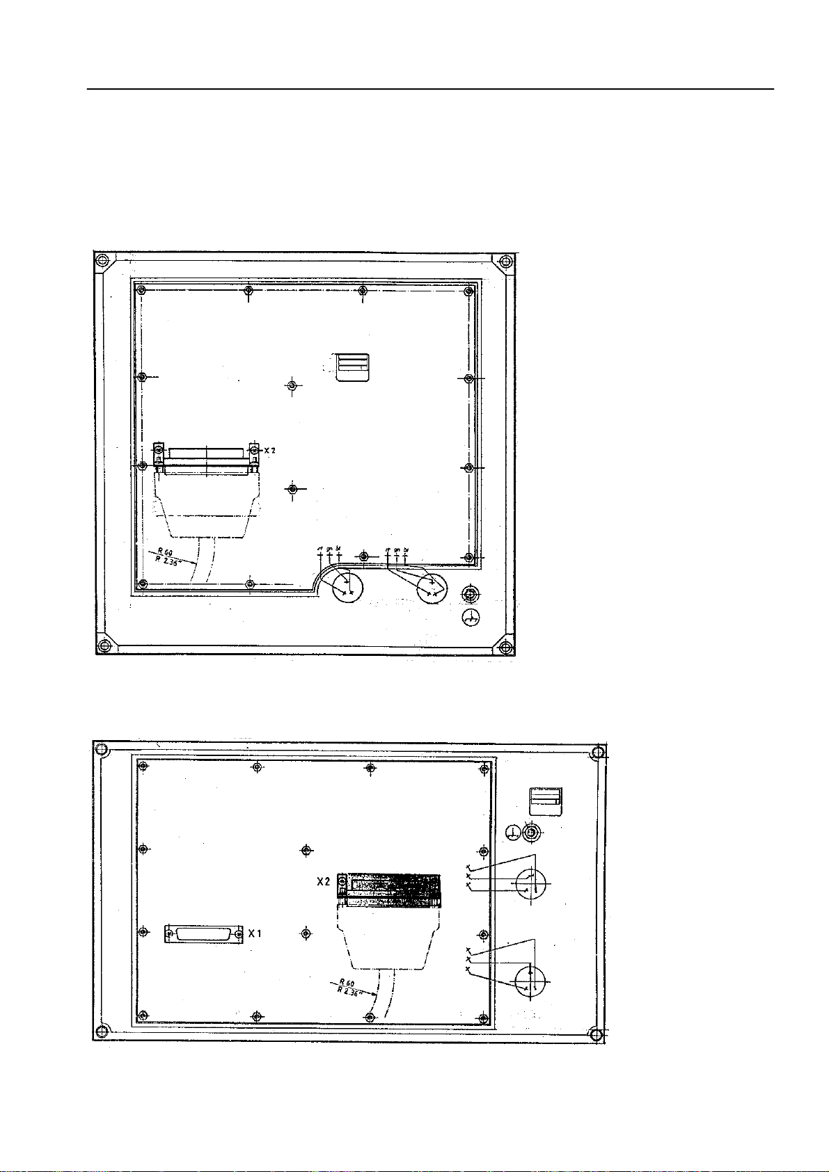
6.4 Connectors on the Visual Display Units
6.4.1 Connectors on the Visual Display Unit BE 212
6.4.1.1 Connector Designation
6.4.1.2 Pin Layout
X1: Connection to the Logic Unit (LE)
Flange socket with male insert (15-pin)
Pin No. Signal
1 and 8 0V supply
2 and 4 + 12 V supply
3,5,6,7 not assgined
9 V SYNC
10 H SYNC
11 not assigned
12 0V signal
13 VIDEO
14,15 not assigned
housing external shield = housing
SERVICE MANUAL TNC 306/360
Page 26
HEIDENHAIN Service
6.4.2 Connectors on the Flat Screen BF 110
6.4.2.1 Connector Desgination
X2
+
-
X1
6.4.2.2 Pin Layout
X1: Power Supply for the Flat Screen
Terminal block (pluggable), 2-pin
Pin No. Signal
- 0V supply
+ + 24V supply
X2: Connection to the Logic Unit (LE)
Flange socket with male insert (15-pin)
Pin No. Signal
1 - 6 not assiged
7 video (P0)
8 not assigned
9 V SYNC
10 not assigned
11 0V signal
12 - 13 not assigned
14 H SYNC
15 clock
housing external shield = housing
 Loading...