


 Loading...
FEATURES
8-channel DAC in 52-lead LQFP and 56-lead LFCSP packages Guaranteed monotonic to 16/14 bits
Nominal output voltage range of −10 V to +10 V Multiple output voltage spans available Thermal shutdown function
Channel monitoring multiplexer GPIO function
System calibration function allowing user-programmable offset and gain
Channel grouping and addressing features Data error checking feature SPI-compatible serial interface
8-Channel, 16-/14-Bit, Serial Input, Voltage Output DAC
AD5362/AD5363
2.5 V to 5.5 V digital interface Digital reset (RESET)
Clear function to user-defined SIGGNDx Simultaneous update of DAC outputs
APPLICATIONS
Instrumentation
Industrial control systems
Level setting in automatic test equipment (ATE)
Variable optical attenuators (VOA)
Optical line cards
FUNCTIONAL BLOCK DIAGRAM
|
DVCC |
VDD |
VSS AGND DGND |
|
|
|
|
LDAC |
|
|
|
|
|
|
|
||
TEMP_OUT |
TEMP |
|
|
|
|
|
|
|
|
|
|
|
|
|
|
|
VREF0 |
SENSOR |
8 |
n = 16 FOR AD5362 |
|
|
|
|
|
|
|
|
|
|
GROUP 0 |
||||
|
CONTROL |
n = 14 FOR AD5363 |
|
|
|
|
|
|
|
|
|
|
|
||||
PEC |
|
|
|
|
|
|
|
|
14 |
OFS0 |
14 |
OFFSET |
|
BUFFER |
|
||
REGISTER |
|
|
|
|
|
|
|
|
|
|
|
|
|||||
MON_IN0 |
VOUT0 TO |
8 |
A/B SELECT |
8 |
TO |
|
|
|
|
REGISTER |
|
DAC 0 |
|
|
|
|
|
|
|
|
|
|
|
|
BUFFER |
|
|
|
|||||||
MON_IN1 |
VOUT7 |
6 |
|
REGISTER |
|
MUX 2s |
|
|
|
|
|
|
OUTPUT BUFFER |
VOUT0 |
|||
|
|
|
|
n |
|
X2A REGISTER |
MUX n |
|
n |
|
|
||||||
MUX |
|
n |
|
n |
A/B |
DAC 0 |
|
|
|||||||||
|
|
X1 REGISTER |
DAC 0 |
|
|
AND POWER- |
|
||||||||||
|
|
|
n |
|
|
MUX |
X2B REGISTER |
2 |
|
REGISTER |
|
|
|
DOWN CONTROL |
|
||
|
|
|
M REGISTER n |
|
|
|
|
|
|
|
|
|
|
|
|||
MON_OUT |
|
|
|
|
· |
|
|
· |
|
|
· |
|
· |
VOUT1 |
|||
|
|
n |
|
n |
|
|
|
|
|
|
|
|
|||||
|
GPIO |
2 |
C REGISTER |
|
|
|
|
|
|
|
|
||||||
GPIO |
|
|
· |
· |
· |
· |
· |
|
|
· |
|
|
· |
|
· |
|
|
REGISTER |
|
|
|
|
|
|
|
VOUT2 |
|||||||||
|
|
|
|
· |
· |
· |
· |
· |
|
|
· |
|
|
· |
|
· |
|
BIN/2SCOMP |
|
|
|
· |
· |
· |
· |
|
|
|
|
|
|
|
|
|
|
|
|
|
n |
|
n |
n |
A/B |
X2A REGISTER |
MUX |
n |
DAC 3 |
n |
|
|
OUTPUT BUFFER |
VOUT3 |
|
SYNC |
|
|
X1 REGISTER |
|
|
DAC 3 |
|
|
AND POWER- |
||||||||
|
|
n |
n |
|
MUX |
X2B REGISTER |
2 |
|
REGISTER |
|
|
|
DOWN CONTROL |
SIGGND0 |
|||
|
|
|
|
|
|
|
|
|
|
|
|
|
|
||||
SDI |
|
|
M REGISTER |
|
|
|
|
|
|
|
|
|
|
|
|||
SERIAL |
|
|
|
|
|
|
|
|
|
|
|
|
|
||||
|
|
n |
|
n |
|
|
|
|
|
|
|
|
|
|
|
|
|
SCLK |
INTERFACE |
|
C REGISTER |
|
|
|
|
|
|
|
|
|
|
|
VREF1 |
||
SDO |
|
|
|
|
|
|
|
|
|
|
|
|
|
|
|
GROUP 1 |
|
|
|
|
|
|
|
|
|
|
14 |
|
n |
|
BUFFER |
|
|||
BUSY |
|
|
|
|
|
|
|
|
|
OFS1 |
OFFSET |
|
|
||||
|
|
|
|
|
|
|
|
|
|
|
|
|
|
|
|||
|
|
|
8 |
A/B SELECT |
8 |
TO |
|
|
|
|
REGISTER |
|
DAC 1 |
|
|
|
|
|
|
|
|
|
|
|
|
|
|
BUFFER |
|
|
|
||||
RESET |
|
|
|
REGISTER |
|
MUX 2s |
|
|
|
|
|
|
OUTPUT BUFFER |
VOUT4 |
|||
|
|
|
|
|
n |
|
X2A REGISTER |
MUX n |
|
n |
|
|
|||||
|
|
|
n |
|
n |
A/B |
DAC 4 |
|
|
||||||||
CLR |
|
|
X1 REGISTER |
DAC 4 |
|
|
AND POWER- |
|
|||||||||
|
|
n |
|
|
MUX |
X2B REGISTER |
2 |
|
REGISTER |
|
|
|
DOWN CONTROL |
|
|||
|
|
|
|
n |
|
|
|
|
|
|
|
|
|
|
|
||
|
STATE |
|
M REGISTER |
|
|
· |
|
|
· |
|
|
· |
|
· |
VOUT5 |
||
|
|
n |
|
n |
|
|
|
|
|
|
|
||||||
|
MACHINE |
|
C REGISTER |
|
|
|
|
|
|
|
|
||||||
|
|
|
|
· |
· |
· |
· |
· |
|
|
· |
|
|
· |
|
· |
|
|
n |
|
|
· |
|
|
· |
|
|
· |
|
· |
VOUT6 |
||||
|
|
|
|
· |
· |
· |
· |
|
|
|
|
|
|
||||
|
|
|
|
· |
· |
· |
· |
|
|
|
· |
|
|
|
|
|
|
|
|
|
|
|
|
n |
A/B |
X2A REGISTER |
|
n |
n |
|
|
OUTPUT BUFFER |
VOUT7 |
||
|
|
|
n |
X1 REGISTER n |
|
|
MUX |
|
DAC 7 |
|
DAC 7 |
|
|
AND POWER- |
|
||
|
|
|
|
MUX |
X2B REGISTER |
|
REGISTER |
|
|
|
SIGGND1 |
||||||
|
AD5362/ |
|
n |
M REGISTER |
n |
|
|
2 |
|
|
|
|
|
|
DOWN CONTROL |
||
|
|
|
|
|
|
|
|
|
|
|
|
|
|
||||
|
AD5363 |
|
n |
C REGISTER |
n |
|
|
|
|
|
|
|
|
|
|
|
05762-001 |
|
|
|
|
|
|
|
|
|
|
|
|
|
|
||||
|
|
|
|
|
|
|
|
|
|
|
|
|
|
|
|
|
|
Figure 1.
Rev. A
Information furnished by Analog Devices is believed to be accurate and reliable. However, no responsibilityisassumedbyAnalogDevicesforitsuse,norforanyinfringementsofpatentsorother rightsofthirdpartiesthatmayresultfromitsuse.Specificationssubjecttochangewithoutnotice.No license is granted by implication or otherwise under any patent or patent rights of Analog Devices. Trademarksandregisteredtrademarksarethepropertyoftheirrespectiveowners.
One Technology Way, P.O. Box 9106, Norwood, MA 02062-9106, U.S.A.
Tel: 781.329.4700 |
www.analog.com |
Fax: 781.461.3113 |
©2008 Analog Devices, Inc. All rights reserved. |

AD5362/AD5363
TABLE OF CONTENTS |
|
Features .............................................................................................. |
1 |
Applications....................................................................................... |
1 |
Functional Block Diagram .............................................................. |
1 |
Revision History ............................................................................... |
2 |
General Description ......................................................................... |
3 |
Specifications..................................................................................... |
4 |
AC Characteristics........................................................................ |
6 |
Timing Characteristics ................................................................ |
7 |
Absolute Maximum Ratings.......................................................... |
10 |
ESD Caution................................................................................ |
10 |
Pin Configuration and Function Descriptions........................... |
11 |
Typical Performance Characteristics ........................................... |
13 |
Terminology .................................................................................... |
15 |
Theory of Operation ...................................................................... |
16 |
DAC Architecture....................................................................... |
16 |
Channel Groups.......................................................................... |
16 |
A/B Registers and Gain/Offset Adjustment............................ |
17 |
Offset DACs ................................................................................ |
17 |
Output Amplifier........................................................................ |
18 |
Transfer Function ....................................................................... |
18 |
Reference Selection .................................................................... |
18 |
Calibration................................................................................... |
19 |
Additional Calibration............................................................... |
19 |
REVISION HISTORY |
|
3/08—Rev. 0 to Rev. A |
|
Added 56-Lead LFCSP_VQ .............................................. |
Universal |
Changes to Table 2............................................................................ |
4 |
Added t23 Parameter ......................................................................... |
7 |
Changes to Figure 4.......................................................................... |
8 |
Changes to Table 6.......................................................................... |
11 |
Changes to A/B Registers and Gain/Offset Adjustment |
|
Section.............................................................................................. |
17 |
Reset Function ............................................................................ |
20 |
Clear Function ............................................................................ |
20 |
BUSY and LDAC Functions...................................................... |
20 |
BIN/2SCOMP Pin...................................................................... |
20 |
Temperature Sensor ................................................................... |
20 |
Monitor Function....................................................................... |
21 |
GPIO Pin ..................................................................................... |
21 |
Power-Down Mode.................................................................... |
21 |
Thermal Shutdown Function ................................................... |
21 |
Toggle Mode................................................................................ |
21 |
Serial Interface ................................................................................ |
22 |
SPI Write Mode .......................................................................... |
22 |
SPI Readback Mode ................................................................... |
22 |
Register Update Rates ................................................................ |
22 |
Packet Error Checking............................................................... |
23 |
Channel Addressing and Special Modes................................. |
23 |
Special Function Mode.............................................................. |
24 |
Applications Information .............................................................. |
26 |
Power Supply Decoupling ......................................................... |
26 |
Power Supply Sequencing ......................................................... |
26 |
Interfacing Examples ................................................................. |
26 |
Outline Dimensions ....................................................................... |
27 |
Ordering Guide .......................................................................... |
28 |
Changes to Calibration Section .................................................... |
19 |
Changes to Reset Function Section and BUSY and LDAC |
|
Functions Section ........................................................................... |
20 |
Changes to Channel Addressing and Special Modes Section .. |
23 |
Updated Outline Dimensions....................................................... |
27 |
Changes to Ordering Guide .......................................................... |
28 |
1/08—Revision 0: Initial Version |
|
Rev. A | Page 2 of 28

GENERAL DESCRIPTION
The AD5362/AD5363 contain eight 16-/14-bit DACs in a single 52-lead LQFP package or 56-lead LFCSP package. The devices provide buffered voltage outputs with a span of 4× the reference voltage. The gain and offset of each DAC can be independently trimmed to remove errors. For even greater flexibility, the device is divided into two groups of four DACs, and the output range of each group can be independently adjusted by an offset DAC.
The AD5362/AD5363 offer guaranteed operation over a wide supply range with VSS from −16.5 V to −4.5 V and VDD from 8 V to 16.5 V. The output amplifier headroom requirement is 1.4 V, operating with a load current of 1 mA.
AD5362/AD5363
The AD5362/AD5363 have a high speed 4-wire serial interface that is compatible with SPI, QSPI™, MICROWIRE™, and DSP interface standards and can handle clock speeds of up to
50 MHz. All the outputs can be updated simultaneously by
taking the LDAC input low. Each channel has a programmable gain and an offset adjust register.
Each DAC output is gained and buffered on chip with respect to an external SIGGNDx input. The DAC outputs can also be switched to SIGGNDx via the CLR pin.
Table 1. High Channel Count Bipolar DACs
Model |
Resolution (Bits) |
Nominal Output Span |
Output Channels |
Linearity Error (LSB) |
|
|
|
|
|
AD5360 |
16 |
4 × VREF (20 V) |
16 |
±4 |
AD5361 |
14 |
4 × VREF (20 V) |
16 |
±1 |
AD5362 |
16 |
4 × VREF (20 V) |
8 |
±4 |
AD5363 |
14 |
4 × VREF (20 V) |
8 |
±1 |
AD5370 |
16 |
4 × VREF (12 V) |
40 |
±4 |
AD5371 |
14 |
4 × VREF (12 V) |
40 |
±1 |
AD5372 |
16 |
4 × VREF (12 V) |
32 |
±4 |
AD5373 |
14 |
4 × VREF (12 V) |
32 |
±1 |
AD5378 |
14 |
±8.75 V |
32 |
±3 |
AD5379 |
14 |
±8.75 V |
40 |
±3 |
|
|
|
|
|
Rev. A | Page 3 of 28

AD5362/AD5363
SPECIFICATIONS
DVCC = 2.5 V to 5.5 V; VDD = 9 V to 16.5 V; VSS = −16.5 V to −4.5 V; VREF = 5 V; AGND = DGND = SIGGND0 = SIGGND1 = 0 V;
RL = open circuit; gain (M), offset (C), and DAC offset registers at default values; all specifications TMIN to TMAX, unless otherwise noted.
Table 2.
Parameter |
B Version1 |
Unit |
|
Test Conditions/Comments |
||||||
ACCURACY |
|
|
|
|
|
|
|
|
|
|
Resolution |
16 |
Bits |
|
AD5362 |
||||||
|
14 |
Bits |
|
AD5363 |
||||||
Integral Nonlinearity (INL) |
±4 |
LSB max |
|
AD5362 |
||||||
|
±1 |
LSB max |
|
AD5363 |
||||||
Differential Nonlinearity (DNL) |
±1 |
LSB max |
Guaranteed monotonic by design over temperature |
|||||||
Zero-Scale Error |
±15 |
mV max |
|
Before calibration |
||||||
Full-Scale Error |
±20 |
mV max |
|
Before calibration |
||||||
Gain Error |
0.1 |
% FSR |
Before calibration |
|||||||
Zero-Scale Error2 |
1 |
LSB typ |
After calibration |
|||||||
Full-Scale Error2 |
1 |
LSB typ |
After calibration |
|||||||
Span Error of Offset DAC |
±75 |
mV max |
|
See the Offset DACs section for details |
||||||
VOUTx3 Temperature Coefficient |
5 |
ppm FSR/°C typ |
Includes linearity, offset, and gain drift |
|||||||
DC Crosstalk2 |
180 |
μV max |
|
Typically 20 μV; measured channel at midscale, full-scale |
||||||
|
|
|
|
change on any other channel |
||||||
|
|
|
|
|
|
|
|
|
|
|
REFERENCE INPUTS (VREF0, VREF1)2 |
|
|
|
|
|
|
|
|
|
|
VREFx Input Current |
±10 |
μA max |
Per input; typically ±30 nA |
|||||||
VREFx Range2 |
2/5 |
V min/V max |
|
±2% for specified operation |
||||||
SIGGND0 AND SIGGND1 INPUTS2 |
|
|
|
|
|
|
|
|
|
|
DC Input Impedance |
50 |
kΩ min |
|
Typically 55 kΩ |
||||||
Input Range |
±0.5 |
V min/V max |
|
|
|
|
|
|
|
|
SIGGNDx Gain |
0.995/1.005 |
min/max |
|
|
|
|
|
|
|
|
|
|
|
|
|
|
|
|
|
|
|
OUTPUT CHARACTERISTICS2 |
|
|
|
|
|
|
|
|
|
|
Output Voltage Range |
VSS + 1.4 |
V min |
|
ILOAD = 1 mA |
||||||
|
VDD − 1.4 |
V max |
|
ILOAD = 1 mA |
||||||
Nominal Output Voltage Range |
−10 to +10 |
V |
|
|
|
|
|
|
|
|
Short-Circuit Current |
15 |
mA max |
|
VOUTx3 to DVCC, VDD, or VSS |
||||||
Load Current |
±1 |
mA max |
|
|
|
|
|
|
|
|
Capacitive Load |
2200 |
pF max |
|
|
|
|
|
|
|
|
DC Output Impedance |
0.5 |
Ω max |
|
|
|
|
|
|
|
|
MONITOR PIN (MON_OUT)2 |
|
|
|
|
|
|
|
|
|
|
Output Impedance |
|
|
|
|
|
|
|
|
|
|
DAC Output at Positive Full Scale |
1000 |
Ω typ |
|
|
|
|
|
|
|
|
DAC Output at Negative Full Scale |
500 |
Ω typ |
|
|
|
|
|
|
|
|
Three-State Leakage Current |
100 |
nA typ |
|
|
|
|
|
|
|
|
Continuous Current Limit |
2 |
mA max |
|
|
|
|
|
|
|
|
DIGITAL INPUTS |
|
|
|
|
|
|
|
|
|
|
Input High Voltage |
1.7 |
V min |
|
DVCC = 2.5 V to 3.6 V |
||||||
|
2.0 |
V min |
|
DVCC = 3.6 V to 5.5 V |
||||||
Input Low Voltage |
0.8 |
V max |
|
DVCC = 2.5 V to 5.5 V |
||||||
Input Current |
±1 |
μA max |
|
|
|
|
|
|
SDI, and SCLK pins |
|
|
RESET, |
|
SYNC, |
|||||||
|
±20 |
μA max |
|
|
|
|
|
|||
|
|
CLR, |
|
BIN/2SCOMP, and GPIO pins |
||||||
Input Capacitance2 |
10 |
pF max |
|
|
|
|
|
|
|
|
Rev. A | Page 4 of 28

AD5362/AD5363
Parameter |
B Version1 |
Unit |
Test Conditions/Comments |
||||
DIGITAL OUTPUTS (SDO, |
|
GPIO, |
|
|
|
|
|
BUSY, |
PEC) |
|
|
|
|
||
Output Low Voltage |
0.5 |
V max |
Sinking 200 μA |
||||
Output High Voltage (SDO) |
DVCC − 0.5 |
V min |
Sourcing 200 μA |
||||
High Impedance Leakage Current |
±5 |
μA max |
SDO only |
||||
High Impedance Output Capacitance2 |
10 |
pF typ |
|
||||
TEMPERATURE SENSOR (TEMP_OUT)2 |
|
|
|
||||
Accuracy |
±1 |
°C typ |
@ 25°C |
||||
|
|
|
|
|
±5 |
°C typ |
−40°C < T < +85°C |
Output Voltage at 25°C |
1.46 |
V typ |
|
||||
Output Voltage Scale Factor |
4.4 |
mV/°C typ |
|
||||
Output Load Current |
200 |
μA max |
Current source only |
||||
Power-On Time |
10 |
ms typ |
To within ±5°C |
||||
|
|
|
|
||||
POWER REQUIREMENTS |
|
|
|
||||
DVCC |
2.5/5.5 |
V min/V max |
|
||||
VDD |
8/16.5 |
V min/V max |
|
||||
VSS |
−16.5/−4.5 |
V min/V max |
|
||||
Power Supply Sensitivity2 |
|
|
|
||||
∆Full Scale/∆VDD |
−75 |
dB typ |
|
||||
∆Full Scale/∆VSS |
−75 |
dB typ |
|
||||
∆Full Scale/∆DVCC |
−90 |
dB typ |
|
||||
DICC |
2 |
mA max |
DVCC = 5.5 V, VIH = DVCC, VIL = GND |
||||
IDD |
8.5 |
mA max |
Outputs = 0 V and unloaded |
||||
ISS |
8.5 |
mA max |
Outputs = 0 V and unloaded |
||||
Power-Down Mode |
|
|
Bit 0 in the control register is 1 |
||||
DICC |
5 |
μA typ |
|
||||
IDD |
35 |
μA typ |
|
||||
ISS |
−35 |
μA typ |
|
||||
Power Dissipation |
|
|
|
||||
Power Dissipation Unloaded (P) |
209 |
mW max |
VSS = −12 V, VDD = 12 V, DVCC = 2.5 V |
||||
Junction Temperature4 |
130 |
°C max |
TJ = TA + PTOTAL × θJA |
||||
1 Temperature range for B version: −40°C to +85°C. Typical specifications are at 25°C. 2 Guaranteed by design and characterization; not production tested.
3 VOUTx refers to any of VOUT0 to VOUT7.
4 θJA represents the package thermal impedance.
Rev. A | Page 5 of 28

AD5362/AD5363
AC CHARACTERISTICS
DVCC = 2.5 V; VDD = 15 V; VSS = −15 V; VREF = 5 V; AGND = DGND = SIGGND0 = SIGGND1 = 0 V; CL = 200 pF; RL = 10 kΩ; gain (M), offset (C), and DAC offset registers at default values; all specifications TMIN to TMAX, unless otherwise noted.
Table 3.
Parameter |
B Version1 |
Unit |
Test Conditions/Comments |
DYNAMIC PERFORMANCE1 |
|
|
|
Output Voltage Settling Time |
20 |
μs typ |
Full-scale change |
|
30 |
μs max |
DAC latch contents alternately loaded with all 0s and all 1s |
Slew Rate |
1 |
V/μs typ |
|
Digital-to-Analog Glitch Energy |
5 |
nV-s typ |
|
Glitch Impulse Peak Amplitude |
10 |
mV max |
|
Channel-to-Channel Isolation |
100 |
dB typ |
VREF0, VREF1 = 2 V p-p, 1 kHz |
DAC-to-DAC Crosstalk |
10 |
nV-s typ |
|
Digital Crosstalk |
0.2 |
nV-s typ |
|
Digital Feedthrough |
0.02 |
nV-s typ |
Effect of input bus activity on DAC output under test |
Output Noise Spectral Density @ 10 kHz |
250 |
nV/√Hz typ |
VREF0 = VREF1 = 0 V |
|
|
|
|
1 Guaranteed by design and characterization; not production tested.
Rev. A | Page 6 of 28
AD5362/AD5363
TIMING CHARACTERISTICS
DVCC = 2.5 V to 5.5 V; VDD = 9 V to 16.5 V; VSS = −16.5 V to −8 V; VREF = 5 V; AGND = DGND = SIGGND = 0 V; CL = 200 pF to GND; RL = open circuit; gain (M), offset (C), and DAC offset registers at default values; all specifications TMIN to TMAX, unless otherwise noted.
Table 4. SPI Interface
Parameter1, 2, 3 |
Limit at TMIN, TMAX |
Unit |
|
|
Description |
|||||||||||||||||||||||
t1 |
20 |
ns min |
|
|
SCLK cycle time |
|||||||||||||||||||||||
t2 |
8 |
ns min |
|
|
SCLK high time |
|||||||||||||||||||||||
t3 |
8 |
ns min |
|
|
SCLK low time |
|||||||||||||||||||||||
t4 |
11 |
ns min |
|
|
|
|
|
|
|
falling edge to SCLK falling edge setup time |
||||||||||||||||||
|
|
SYNC |
|
|||||||||||||||||||||||||
t5 |
20 |
ns min |
|
|
|
|
|
|
|
|
|
|
|
|
|
|
|
|
|
|
|
|
|
|
|
|||
|
|
Minimum |
SYNC |
high time |
||||||||||||||||||||||||
t6 |
10 |
ns min |
|
|
|
|
|
|
|
|
|
|
|
|
|
|
|
|
|
|
|
|
|
|||||
|
|
24th SCLK falling edge to |
SYNC |
rising edge |
||||||||||||||||||||||||
t7 |
5 |
ns min |
|
|
Data setup time |
|||||||||||||||||||||||
t8 |
5 |
ns min |
|
|
Data hold time |
|||||||||||||||||||||||
t94 |
42 |
ns max |
|
|
|
|
|
|
rising edge to |
|
|
|
|
|
|
falling edge |
||||||||||||
|
|
SYNC |
|
|
BUSY |
|
|
|||||||||||||||||||||
t10 |
1/1.5 |
μs typ/μs max |
|
|
|
|
|
pulse width low (single-channel update); see Table 9 |
||||||||||||||||||||
|
BUSY |
|
|
|||||||||||||||||||||||||
t11 |
600 |
ns max |
|
Single-channel update cycle time |
||||||||||||||||||||||||
t12 |
20 |
ns min |
|
|
|
|
|
|
rising edge to |
|
|
|
|
|
falling edge |
|||||||||||||
|
|
SYNC |
|
LDAC |
|
|||||||||||||||||||||||
t13 |
10 |
ns min |
|
|
|
|
|
|
|
|
|
|
|
|
|
|
|
|||||||||||
|
|
LDAC |
pulse width low |
|||||||||||||||||||||||||
t14 |
3 |
μs max |
|
|
|
|
|
|
|
|
|
|
|
|
|
|
||||||||||||
|
|
BUSY |
rising edge to DAC output response time |
|||||||||||||||||||||||||
t15 |
0 |
ns min |
|
|
|
|
|
|
|
|
|
|
|
falling edge |
||||||||||||||
|
|
BUSY |
rising edge to |
LDAC |
||||||||||||||||||||||||
t16 |
3 |
μs max |
|
|
|
|
|
|
|
|
|
|
|
|
||||||||||||||
|
|
LDAC |
falling edge to DAC output response time |
|||||||||||||||||||||||||
t17 |
20/30 |
μs typ/μs max |
|
|
DAC output settling time |
|||||||||||||||||||||||
t18 |
140 |
ns max |
|
|
|
|
|
|
|
|
|
|
|
|
||||||||||||||
|
|
CLR/RESET pulse activation time |
||||||||||||||||||||||||||
t19 |
30 |
ns min |
|
|
|
|
|
|
|
|
||||||||||||||||||
|
|
RESET |
pulse width low |
|||||||||||||||||||||||||
t20 |
400 |
μs max |
|
|
|
|
|
low |
||||||||||||||||||||
|
|
RESET |
time indicated by |
BUSY |
||||||||||||||||||||||||
t21 |
270 |
ns min |
|
|
|
|
|
|||||||||||||||||||||
|
|
Minimum |
SYNC |
high time in readback mode |
||||||||||||||||||||||||
t225 |
25 |
ns max |
|
|
SCLK rising edge to SDO valid |
|||||||||||||||||||||||
t23 |
80 |
ns max |
|
|
RESET |
rising edge to |
BUSY |
falling edge |
||||||||||||||||||||
|
|
|
|
|
|
|
|
|
|
|
|
|
|
|
|
|
|
|
|
|
|
|
|
|
|
|
|
|
1 Guaranteed by design and characterization; not production tested.
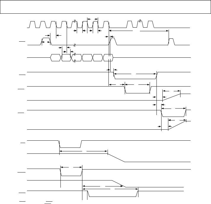
2 All input signals are specified with tR = tF = 2 ns (10% to 90% of DVCC) and timed from a voltage level of 1.2 V. 3 See Figure 4 and Figure 5.
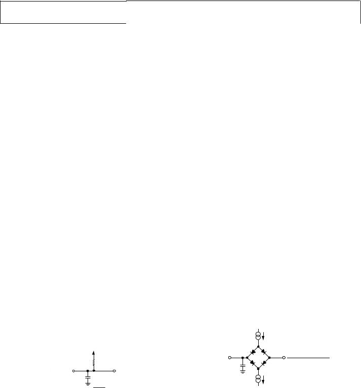
4 t9 is measured with the load circuit shown in Figure 2. 5 t22 is measured with the load circuit shown in Figure 3.
|
DVCC |
|
|
RL |
|
TO |
2.2kΩ |
|
OUTPUT |
|
VOL |
PIN |
CL |
05762-002 |
|
50pF |
|
|
|
Figure 2. Load Circuit for BUSY Timing Diagram
|
200µA |
IOL |
|
TO OUTPUT |
|
|
VOH (MIN) – VOL (MAX) |
PIN |
CL |
|
2 |
|
|
|
|
|
50pF |
|
05762-003 |
|
200µA |
IOH |
|
|
|
Figure 3. Load Circuit for SDO Timing Diagram
Rev. A | Page 7 of 28
AD5362/AD5363
|
|
|
t1 |
|
|
SCLK |
1 |
2 |
24 |
1 |
24 |
|
|
t3 |
t2 |
|
t11 |
|
t4 |
|
t6 |
|
|
SYNC |
t5 |
|
|
|
|
|
|
t7 |
|
|
|
|
|
t8 |
|
|
|
SDI |
DB23 |
|
DB0 |
|
|
|
|
|
t9 |
|
|
BUSY |
|
|
|
|
t10 |
|
|
|
|
|
|
|
|
|
t12 |
|
t13 |
LDAC1 |
|
|
|
|
t17 |
VOUTx1 |
|
|
|
|
t14 |
|
|
|
|
|
t15 |
|
|
|
|
|
t13 |
LDAC2 |
|
|
|
|
|
|
|
|
|
|
t17 |
VOUTx2 |
|
|
|
|
t16 |
CLR
t18
VOUTx
t19
RESET
VOUTx
t18
t20
BUSY
 t23
t23 
1LDAC ACTIVE DURING BUSY.
2LDAC ACTIVE AFTER BUSY.
Figure 4. SPI Write Timing
05762-004
Rev. A | Page 8 of 28
AD5362/AD5363
t22
SCLK |
48 |
t21
SYNC
SDI |
DB23 |
DB0 |
DB23 |
|
DB0 |
|
|
INPUT WORD SPECIFIES |
|
NOP CONDITION |
|
|
|
REGISTER TO BE READ |
|
|
|
SDO |
|
|
DB0 DB23 |
DB15 |
DB0 |
|
|
LSB FROM PREVIOUS WRITE |
SELECTED REGISTER DATA CLOCKED OUT |
|
|
|
|
|
|
|
|
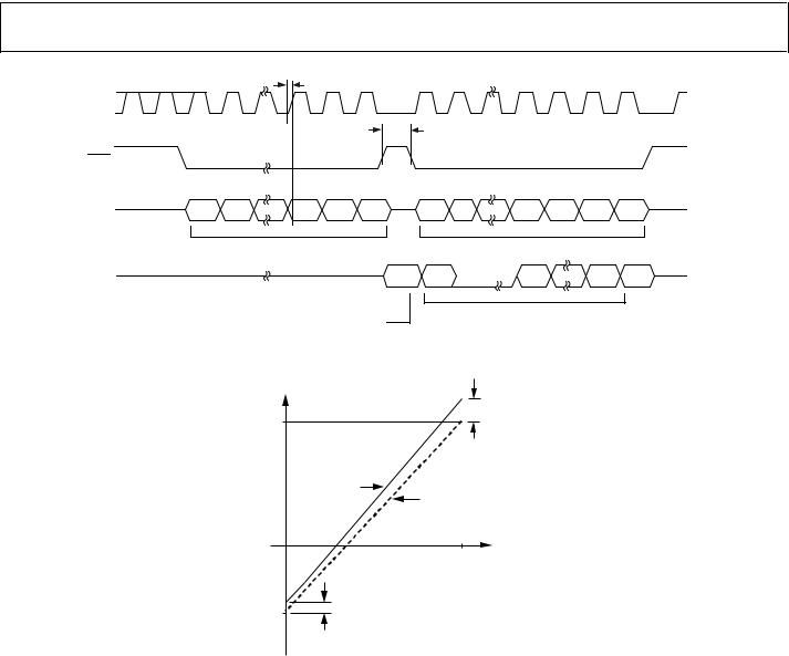
Figure 5. SPI Read Timing
05762-005
OUTPUT |
|
|
VOLTAGE |
|
FULL-SCALE |
VMAX |
|
ERROR |
|
+ |
|
|
|
ZERO-SCALE |
|
|
ERROR |
|
ACTUAL |
|
|
TRANSFER |
|
|
FUNCTION |
|
|
|
IDEAL |
|
|
TRANSFER |
|
|
FUNCTION |
0 |
DAC CODE |
2N – 1 |
|
|
n = 16 FOR AD5362 |
|
|
n = 14 FOR AD5363 |
|
ZERO-SCALE |
|
VMIN |
ERROR |
|
|
|
05762-006 |
Figure 6. DAC Transfer Function
Rev. A | Page 9 of 28
Loading...