


 Loading...
TEXAS INSTRUMENTS SN65LVDS32B, SN65LVDT32B, SN65LVDS3486B, SN65LVDT3486B, SN65LVDS9637B Technical data
...SN65LVDS32B, SN65LVDT32B
SN65LVDS3486B, SN65LVDT3486B
SN65LVDS9637B, SN65LVDT9637B
www.ti.com |
SLLS440B – OCTOBER 2000 – REVISED APRIL 2007 |
|
HIGH-SPEED DIFFERENTIAL RECEIVERS
FEATURES
∙Meets or Exceeds the Requirements of ANSI EIA/TIA-644 Standard for Signaling Rates (1) up to 400 Mbps
∙Operates With a Single 3.3-V Supply
∙–2-V to 4.4-V Common-Mode Input Voltage Range
∙Differential Input Thresholds <50 mV With 50 mV of Hysteresis Over Entire CommonMode Input Voltage Range
∙Integrated 110-Ω Line Termination Resistors
Offered With the LVDT Series
∙Propagation Delay Times 4 ns (typ)
∙Active Fail Safe Assures a High-Level Output With No Input
∙Bus-Pin ESD Protection Exceeds 15 kV HBM
∙Inputs Remain High-Impedance on Power Down
∙Recommended Maximum Parallel Rate of 200 M-Transfer/s
∙Available in Small-Outline Package With 1,27-mm Terminal Pitch
∙Pin-Compatible With the AM26LS32, MC3486, or µA9637
DESCRIPTION
This family of differential line receivers offers improved performance and features that implement the electrical characteristics of low-voltage differential signaling (LVDS). LVDS is defined in the TIA/EIA-644 standard. This improved performance represents the second generation of receiver products for this standard, providing a better overall solution for the cabled environment. This generation of products is an extension to TI'soverall product portfolio and is not necessarily a replacement for older LVDS receivers.
|
|
|
SN65LVDS32B |
||
|
|
|
SN65LVDT32B |
||
|
D PACKAGE |
|
Logic Diagram |
||
|
(TOP VIEW) |
|
(positive logic) |
||
1B |
1 |
16 |
VCC |
G |
|
G |
|||||
1A |
2 |
15 |
4B |
||
SN65LVDT32B |
|||||
1Y |
3 |
14 |
4A |
ONLY (4 Places) |
|
1A |
|||||
G |
|
|
4Y |
||
4 |
13 |
1B |
|||
2Y |
5 |
12 |
G |
||
|
|||||
2A |
6 |
11 |
3Y |
2A |
|
2B |
7 |
10 |
3A |
||
2B |
|||||
GND |
8 |
9 |
3B |
||
|
|||||
|
|
|
|
3A |
|
|
|
|
|
3B |
|
|
|
|
|
4A |
|
|
|
|
|
4B |
|
|
|
|
SN65LVDS3486B |
||
|
|
|
SN65LVDT3486B |
||
|
D PACKAGE |
|
Logic Diagram |
||
|
(TOP VIEW) |
|
(positive logic) |
||
1B |
1 |
16 |
VCC |
SN65LVDT3486B |
|
ONLY (4 Places) |
|||||
1A |
2 |
15 |
4B |
1A |
|
|
|||||
1Y |
3 |
14 |
4A |
1B |
|
1,2EN |
4 |
13 |
4Y |
1,2EN |
|
|
|||||
2Y |
5 |
12 |
3,4EN |
2A |
|
2A |
6 |
11 |
3Y |
2B |
|
2B |
7 |
10 |
3A |
3A |
|
GND |
8 |
9 |
3B |
||
|
|||||
|
|
|
|
3B |
|
|
|
|
|
3,4EN |
|
|
|
|
|
4A |
|
|
|
|
|
4B |
|
|
|
|
SN65LVDS9637B |
||
|
|
|
SN65LVDT9637B |
||
|
D PACKAGE |
|
Logic Diagram |
||
|
(TOP VIEW) |
|
(positive logic) |
||
|
|
|
|
||
VCC |
1 |
8 |
1A |
1A |
|
1Y |
2 |
7 |
1B |
||
|
|||||
2Y |
3 |
6 |
2A |
1B |
|
GND |
4 |
5 |
2B |
SN65LVDT9637B |
|
ONLY |
|||||
|
|
|
|
2A |
|
|
|
|
|
2B |
|
1Y
2Y
3Y
4Y
1Y
2Y
3Y
4Y
1Y
2Y
(1)Signaling rate, 1/t, where t is the minimum unit interval and is expressed in the units bit/s (bits per second).
Please be aware that an important notice concerning availability, standard warranty, and use in critical applications of Texas Instruments semiconductor products and disclaimers thereto appears at the end of this data sheet.
PRODUCTION DATA information is current as of publication date. |
Copyright © 2000–2007, Texas Instruments Incorporated |
Products conform to specifications per the terms of the Texas |
|
Instruments standard warranty. Production processing does not |
|
necessarily include testing of all parameters. |
|
SN65LVDS32B, SN65LVDT32B
SN65LVDS3486B, SN65LVDT3486B
SN65LVDS9637B, SN65LVDT9637B
www.ti.com
SLLS440B – OCTOBER 2000 – REVISED APRIL 2007
These devices have limited built-in ESD protection. The leads should be shorted together or the device placed in conductive foam during storage or handling to prevent electrostatic damage to the MOS gates.
DESCRIPTION (CONTINUED)
Improved features include an input common-mode voltage range 2 V wider than the minimum required by the standard. This will allow longer cable lengths by tripling the allowable ground noise tolerance to 3 V between a driver and receiver. TI has additionally introduced an even wider input common-mode voltage range of –4 to 5 V in their SN65LVDS/T33 and SN65LVDS/T34.
Precise control of the differential input voltage thresholds now allows for inclusion of 50 mV of input voltage hysteresis to improve noise rejection on slowly changing input signals. The input thresholds are still no more than ±50 mV over the full input common-mode voltage range.
The high-speed switching of LVDS signals almost always necessitates the use of a line impedance matching resistor at the receiving-end of the cable or transmission media. The SN65LVDT series of receivers eliminates this external resistor by integrating it with the receiver. The non-terminated SN65LVDS series is also available for multidrop or other termination circuits.
The receivers can withstand ±15-kV human-body model (HBM) and ±600 V-machine model (MM) electrostatic discharges to the receiver input pins with respect to ground without damage. This provides reliability in cabled and other connections where potentially damaging noise is always a threat.
The receivers also include a (patent pending) fail-safe circuit that will provide a high-level output within 600 ns after loss of the input signal. The most common causes of signal loss are disconnected cables, shorted lines, or powered-down transmitters. This prevents noise from being received as valid data under these fault conditions. This feature may also be used for wired-OR bus signaling.
The intended application of these devices and signaling technique is for point-to-point baseband data transmission over controlled impedance media of approximately 100 Ω. The transmission media may be printed-circuit board traces, backplanes, or cables. The ultimate rate and distance of data transfer is dependent upon the attenuation characteristics of the media and the noise coupling to the environment.
The SN65LVDS32B, SN65LVDT32B, SN65LVDS3486B, SN65LVDT3486B, SN65LVDS9637B, and SN65LVDT9637B are characterized for operation from –40°C to 85°C.
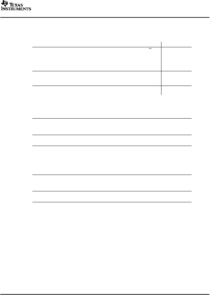
AVAILABLE OPTIONS
PART NUMBER(1) |
NUMBER OF |
TERMINATION |
SYMBOLIZATION |
|
RECEIVERS |
RESISTOR |
|||
|
|
|||
SN65LVDS32BD |
4 |
No |
LVDS32B |
|
SN65LVDT32BD |
4 |
Yes |
LVDT32B |
|
SN65LVDS3486BD |
4 |
No |
LVDS3486 |
|
SN65LVDT3486BD |
4 |
Yes |
LVDT3486 |
|
SN65LVDS9637BD |
2 |
No |
DK637B |
|
SN65LVDT9637BD |
2 |
Yes |
DR637B |
(1)Add the suffix R for taped and reeled carrier.
2 |
Submit Documentation Feedback |
SN65LVDS32B, SN65LVDT32B SN65LVDS3486B, SN65LVDT3486B
SN65LVDS9637B, SN65LVDT9637B
www.ti.com
SLLS440B – OCTOBER 2000 – REVISED APRIL 2007
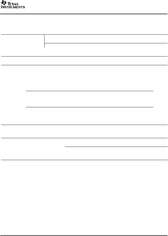
FUNCTION TABLES
SN65LVDS32B and SN65LVDT32B
DIFFERENTIAL INPUT |
|
ENABLES(1) |
OUTPUT(1) |
||
A-B |
|
G |
G |
Y |
|
VID ³ –32 mV |
H |
X |
H |
||
X |
L |
H |
|||
|
|
||||
–100 mV < VID £ |
–32 mV |
H |
X |
? |
|
X |
L |
? |
|||
|
|
||||
VID £ –100 mV |
H |
X |
L |
||
X |
L |
L |
|||
|
|
||||
X |
|
L |
H |
Z |
|
Open |
|
H |
X |
H |
|
|
X |
L |
H |
||
|
|
||||
(1)H = high level, L = low level, X = irrelevant, Z = high impedance (off), ? = indeterminate
SN65LVDS3486B and SN65LVDT3486B
DIFFERENTIAL INPUT |
ENABLES(1) |
OUTPUT(1) |
A-B |
EN |
Y |
VID ³ –32 mV |
H |
H |
–100 mV < VID £ –32 mV |
H |
? |
VID £ –100 mV |
H |
L |
X |
L |
Z |
Open |
H |
H |
(1)H = high level, L = low level, X = irrelevant, Z = high impedance (off), ? = indeterminate
SN65LVDS9637B and SN65LVDT9637B
DIFFERENTIAL INPUT |
OUTPUT(1) |
A-B |
Y |
VID³ -32 mV |
H |
–100 mV < VID£ -32 mV |
? |
VID£ -100 mV |
L |
Open |
H |
(1) H = high level, L = low level, ? = indeterminate |
|
Submit Documentation Feedback |
3 |

SN65LVDS32B, SN65LVDT32B
SN65LVDS3486B, SN65LVDT3486B
SN65LVDS9637B, SN65LVDT9637B
www.ti.com
SLLS440B – OCTOBER 2000 – REVISED APRIL 2007
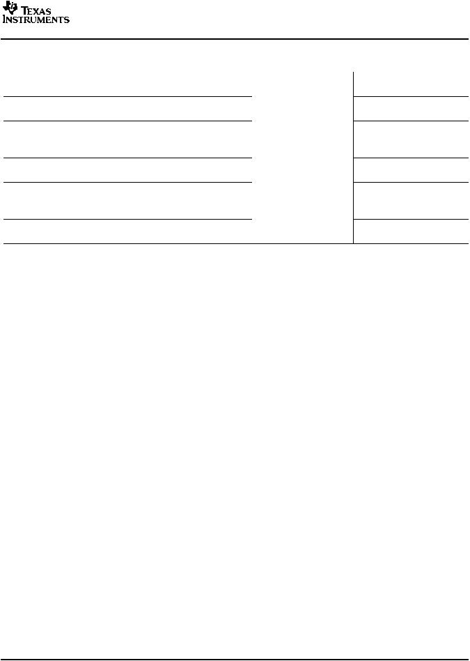
EQUIVALENT INPUT AND OUTPUT SCHEMATIC DIAGRAMS
|
|
|
|
|
VCC |
|
|
Attenuation |
|
|
|
|
|
|
|
Network |
|
|
|
|
|
|
|
VCC |
|
|
|
6.5 kΩ |
6.5 kΩ |
|
|
|
|
|
|
|
|
|
|
1 pF |
60 kΩ |
|
Attenuation |
Network |
Attenuation |
Network |
|
|
|
|
|||||
|
|
A Input |
B Input |
||||
200 kΩ |
|
|
7 V |
||||
|
|
7 V |
|
|
|
||
3 pF |
250 kΩ |
|
7 V |
|
|
|
7 V |
|
|
|
|
|
|
||
|
|
|
|
LVDT Only 110 Ω |
|
|
|
|
|
|
VCC |
|
|
|
|
|
|
|
|
|
|
VCC |
|
|
300 kΩ |
|
|
|
|
|
|
|
(G Only) |
|
|
|
|
|
|
Enable |
50 Ω |
|
|
|
37 Ω |
|
|
|
|
|
|
|
|||
Inputs |
|
|
|
|
|
||
|
|
|
|
|
|
|
|
|
|
|
|
|
|
|
Y Output |
7 V |
|
|
|
|
|
7 V |
|
|
|
|
|
|
|
|
|
|
|
300 kΩ |
|
|
|
|
|
(EN and G Only) |
|
|
|
|
|
|
|
4 |
Submit Documentation Feedback |
SN65LVDS32B, SN65LVDT32B SN65LVDS3486B, SN65LVDT3486B
SN65LVDS9637B, SN65LVDT9637B
www.ti.com
SLLS440B – OCTOBER 2000 – REVISED APRIL 2007
ABSOLUTE MAXIMUM RATINGS
over operating free-air temperature range (unless otherwise noted)(1)
|
|
|
|
UNIT |
V |
CC |
Supply voltage range(2) |
|
–0.5 V to 4 V |
|
|
|
|
|
|
|
|
Enables or Y |
–0.5 V to VCC + 3 V |
|
|
Voltage range |
A or B |
–4 V to 6 V |
|
|
|
|VA– VB| (LVDT) |
1 V |
|
|
Electrostatic discharge: |
A, B, and GND(3) |
Class 3, A: 15 kV, B: 600 V |
|
|
Continuous power dissipation |
|
See Dissipation Rating Table |
|
|
Storage temperature range |
|
–65°C to 150°C |
|
|
Lead temperature 1,6 mm (1/16 inch) from case for 10 seconds |
260°C |
|
(1)Stresses beyond those listed under absolute maximum ratings may cause permanent damage to the device. These are stress ratings only, and functional operation of the device at these or any other conditions beyond those indicated under recommended operating conditions is not implied. Exposure to absolute-maximum-rated conditions for extended periods may affect device reliability.
(2)All voltage values, except differential I/O bus voltages, are with respect to network ground terminal.
(3)Tested in accordance with MIL-STD-883C Method 3015.7.
DISSIPATION RATING TABLE
PACKAGE |
T ≤ 25°C |
OPERATING FACTOR(1) |
T = 85°C |
A |
ABOVE TA = 25°C |
A |
|
|
POWER RATING |
POWER RATING |
|
D8 |
725 mW |
5.8 mW/°C |
377 mW |
D16 |
950 mW |
7.6 mW/°C |
494 mW |
(1)This is the inverse of the junction-to-ambient thermal resistance when board-mounted and with no air flow.
RECOMMENDED OPERATING CONDITIONS
|
|
|
MIN |
NOM |
MAX |
UNIT |
VCC |
Supply voltage |
|
3 |
3.3 |
3.6 |
V |
VIH |
High-level input voltage |
Enables |
2 |
|
|
V |
VIL |
Low-level input voltage |
Enables |
|
|
0.8 |
V |
| VID| |
Magnitude of differential input voltage |
LVDS |
0.1 |
|
3 |
V |
LVDT |
|
|
0.8 |
V |
||
|
|
|
|
|||
VI or VIC |
Voltage at any bus terminal (separately or common-mode) |
–2 |
|
4.4 |
V |
|
TA |
Operating free-air temperature |
|
–40 |
|
85 |
°C |
Submit Documentation Feedback |
5 |

SN65LVDS32B, SN65LVDT32B
SN65LVDS3486B, SN65LVDT3486B
SN65LVDS9637B, SN65LVDT9637B
www.ti.com
SLLS440B – OCTOBER 2000 – REVISED APRIL 2007
ELECTRICAL CHARACTERISTICS
over recommended operating conditions (unless otherwise noted)
|
PARAMETER |
VIT1 |
Positive-going differential input voltage threshold |
VIT2 |
Negative-going differential input voltage threshold |
VIT3 |
Differential input fail-safe voltage threshold |
VID(HYS) |
Differential input voltage hysteresis, VIT1– VIT2 |
VOH |
High-level output voltage |
VOL |
Low-level output voltage |
ICC |
Supply current |
II |
Input current (A or B inputs) |
IID |
Differential input current |
|
(IIA - IIB) |
||
|
||
II(OFF) |
Power-off input current |
|
(A or B inputs) |
'32Bor '3486B
'9637B
SN65LVDS
SN65LVDT
SN65LVDS
SN65LVDT
SN65LVDS
SN65LVDT
IIH |
High-level input current (enables) |
IIL |
Low-level input current (enables) |
IOZ |
High-impedance output current |
CI |
Input capacitance, A or B input to GND |
(1) All typical values are at 25°C and with a 3.3 V supply.
TEST CONDITIONS |
MIN TYP(1) |
MAX |
UNIT |
VIB = -2 V or 4.4 V, |
|
50 |
mV |
–50 |
|
||
See Figure 1 and Figure 2 |
|
|
|
See Table 1 and Figure 5 |
–32 |
–100 |
mV |
|
50 |
|
mV |
IOH = –4 mA |
2.4 |
|
V |
IOL = 4 mA |
|
0.4 |
V |
G or EN at VCC, No load, Steady-state |
16 |
23 |
|
G or EN at GND |
1.1 |
5 |
mA |
No load, Steady-state |
8 |
12 |
|
VI = 0 V, Other input open |
|
±20 |
|
VI = 2.4 V, Other input open |
|
±20 |
µA |
VI = –2 V, Other input open |
|
±40 |
|
|
|
||
VI = 4.4 V, Other input open |
|
±40 |
|
VI = 0 V, Other input open |
|
±40 |
|
VI = 2.4 V, Other input open |
|
±40 |
µA |
VI = –2 V, Other input open |
|
±80 |
|
|
|
||
VI = 4.4 V, Other input open |
|
±80 |
|
VID = 100 mV, VIC= –2 V or 4.4 V, |
|
±3 |
µA |
See Figure 1 |
|
|
|
VID = 0.2 V, VIC = –2 V or 4.4 V |
1.55 |
2.22 |
mA |
VA or VB = 0 V or 2.4 V, VCC = 0 V |
|
±20 |
|
VA or VB = –2 V or 4.4 V, VCC = 0 V |
|
±35 |
µA |
VA or VB = 0 V or 2.4 V, VCC = 0 V |
|
±30 |
|
|
|
||
VA or VB = –2 V or 4.4 V, VCC = 0 V |
|
±50 |
|
VIH = 2 V |
|
10 |
µA |
VIL = 0.8 V |
|
10 |
µA |
|
|
±10 |
µA |
VI = 0.4 sin (4E6πt) + 0.5 V |
5 |
|
pF |
6 |
Submit Documentation Feedback |
SN65LVDS32B, SN65LVDT32B SN65LVDS3486B, SN65LVDT3486B
SN65LVDS9637B, SN65LVDT9637B
www.ti.com
SLLS440B – OCTOBER 2000 – REVISED APRIL 2007
SWITCHING CHARACTERISTICS
over operating free-air temperature range (unless otherwise noted)
|
PARAMETER |
tPLH |
Propagation delay time, low-to-high-level output |
tPHL |
Propagation delay time, high-to-low-level output |
td1 |
Delay time, fail-safe deactivate time |
td2 |
Delay time, fail-safe activate time |
tsk(p) |
Pulse skew (|tPHL1 - tPLH1|) |
t |
Output skew(2) |
sk(o) |
|
t |
Part-to-part skew(3) |
sk(pp) |
|
tr |
Output signal rise time |
tf |
Output signal fall time |
tPHZ |
Propagation delay time, high-level-to-high-impedance output |
tPLZ |
Propagation delay time, low-level-to-high-impedance output |
tPZH |
Propagation delay time, high-impedance -to-high-level output |
tPZL |
Propagation delay time, high-impedance-to-low-level output |
TEST CONDITIONS |
MIN |
TYP(1) |
MAX |
UNIT |
|
See Figure 3 |
2.5 |
4 |
6 |
ns |
|
2.5 |
4 |
6 |
ns |
||
|
|||||
See Figure 3 and |
|
|
9 |
ns |
|
Figure 6 |
0.3 |
|
1.5 |
µs |
|
|
|
200 |
|
ps |
|
|
|
150 |
|
ps |
|
CL = 10 pF, See Figure 3 |
|
|
1 |
ns |
|
|
|
0.8 |
|
ns |
|
|
|
0.8 |
|
ns |
|
|
|
5.5 |
9 |
ns |
|
See Figure 4 |
|
4.4 |
9 |
ns |
|
|
3.8 |
9 |
ns |
||
|
|
||||
|
|
7 |
9 |
ns |
(1)All typical values are at 25°C and with a 3.3-V supply.
(2)tsk(o) is the magnitude of the time difference between the tPLH or tPHL of all receivers of a single device with all of their inputs driven together.
(3)tsk(pp) is the magnitude of the time difference in propagation delay times between any specified terminals of two devices when both devices operate with the same supply voltages, at the same temperature, and have identical packages and test circuits.
Submit Documentation Feedback |
7 |
Loading...