


PT79SR105H
Texas Instruments PT79SR105H, PT79SR105S, PT79SR105V, PT79SR108H, PT79SR108S Datasheet
...
For assistance or to order, call (800) 531-5782
Power Trends, Inc. 27715 Diehl Road, Warrenville, IL 60555 (800) 531-5782 Fax: (630) 393-6902 http://www.powertrends.com
22
Application Notes
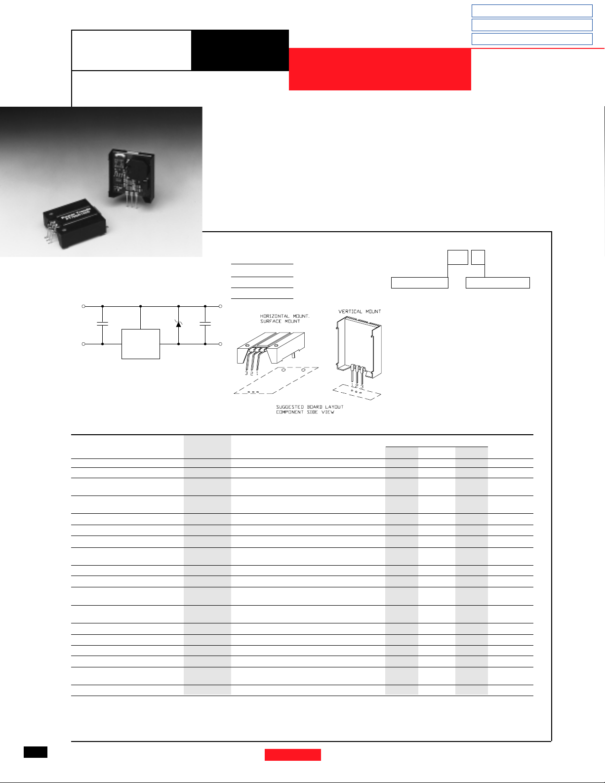
Mechanical Outline
Product Selector Guide
Revised 5/15/98
PT79SR100 Series
-1.5 AMP NEGATIVE STEP-DOWN
INTEGRATED SWITCHING REGULATOR
• High Efficiency > 85%
• Self-Contained Inductor
• Short Circuit Protection
• Over-Temperature Protection
The PT79SR100 Series is a new
line of Negative Input/Negative Out-
put 3-terminal Integrated Switching
Regulators (ISRs). These ISRs have a
maximum output current of -1.5 Amps
and an output voltage that is laser
trimmed to most industry standard volt-
ages. They have excellent line and load
regulation, and are ideal for applications,
such as RS232 and Ethernet communica-
tions, ECL logic, and op-amp circuitry.
PT79SR1
COMCOM
-Vin
C1
1
23
C2D1
-Vout
Pin-Out Information
Pin Function
1 GND
2-V
in
3-V
out
Ordering Information
PT79SR1
XX
Y
Output Voltage
05 = -5.0 Volts
52 = -5.2 Volts
08 = -8.0 Volts
09 = -9.0 Volts
12 = -12.0 Volts
15 = -15.0 Volts
Package Suffix
V = Vertical Mount
S = Surface Mount
H = Horizontal
Mount
Standard Application
C1 = Optional ceramic (1µF)
C2 = Optional ceramic (1-5µF)
D1 = Zener diode required to clamp
turn-on overshoot
(See Application Note)
Specifications
Characteristics
PT79SR100 SERIES
(T
a
= 25°C unless noted) Symbols Conditions Min Typ Max Units
Output Current I
o
Over V
in
range -0.1* — -1.5 A
Short Circuit Current I
sc
V
in
=V
o
-4V — -3.5 — Apk
Input Voltage Range V
in
I
o
=-0.1 to -1.5 A V
o
=-5V -9 — -30 V
-0.1 ≥ I
o
≥ -1.5 A V
o
=-15V -19 — -30 V
Output Voltage Tolerance ∆V
o
Over Vin range, I
o
=-1.5 A
— ±1.0 ±3.0 %V
o
T
a
=-20°C to shutdown
Line Regulation Reg
line
Over V
in
range — ±1.0 ±2.0 %V
o
Load Regulation Reg
load
-0.1 ≤ I
o
≤ -1.5 A — ±0.5 ±1.0 %V
o
V
o
Ripple/Noise V
n
V
in
=-15V, I
o
=-1.0 A,V
o
=-5V — 35 — mV
pp
Transient Response t
tr
50% load change — 100 — µSec
V
o
=overshoot/undershoot — 30 — %V
o
Efficiency η V
in
=-10V, I
o
=-1.0A, V
o
=-5V — 85 — %
Switching Frequency ƒ
o
Over V
in
and I
o
ranges 0.95 1.0 1.05 MHz
Absolute Maximum T
a
-40 — +85 °C
Operating Temperature Range
Recommended Operating T
a
Free Air Convection, (40-60LFM)
-40 — +60** °C
Temperature Range Over V
in
and I
o
ranges
Thermal Resistance θ
ja
Free Air Convection, (40-60LFM) — 45 — °C/W
Temperature Coefficient T
c
Over V
in
and I
o
ranges — ±0.5 ±1.5 mV/°C
Storage Temperature T
s
— -40 — +125 °C
Mechanical Shock — Per Mil-STD-883D, Method 2002.3 — 500 — G’s
Mechanical Vibration — Per Mil-STD-883D, Method 2007.2,
—5
—
G’s
20-2000 Hz, soldered in a PC board
Weight — — — 7.0 — Grams
* ISR will operate down to no load with reduced specifications. ** See Thermal Derating chart.
Pkg Style 500
 Loading...